

Raspberry Pi is an ARM architecture processor based board designed for electronic engineers and hobbyists. The PI is one of most trusted project development platforms out there now. With higher processor speed and 1 GB RAM, the PI can be used for many high profile projects like Image processing and Internet of Things.
For doing any of high profile projects, one need to understand the basic functions of PI. We will be covering all the basic functionalities of Raspberry Pi in these tutorials. In each tutorial we will discuss one of functions of PI. By the end of this Raspberry Pi Tutorial Series, you will be able to do high profile projects by yourself. Go through below tutorials:
- Getting Started with Raspberry Pi
- Raspberry Pi Configuration
- LED Blinky
- Raspberry Pi Button Interfacing
- Raspberry Pi PWM generation
- Controlling DC Motor using Raspberry Pi
- Stepper Motor Control with Raspberry Pi
In this Raspberry Pi shift register tutorial, we will Interface Shift Register with Pi. PI has 26 GPIO pins, but when we do projects like 3D printer, the output pins provided by PI are not enough. So we need more output pins, for adding more output pins to PI, we add Shift Register Chip. A Shift Register chip takes data from PI board serially and gives parallel output. The chip is of 8bit, so the chip takes 8bits from PI serially and then provides the 8bit logic output through 8 output pins.
For 8 bit shift register, we are going to use IC 74HC595. It’s a 16 PIN chip. The pin configuration of the chip is explained later below in this tutorial.
In this tutorial, we will use three PI’s GPIO pins to get eight outputs from Shift Register Chip. Remember here the PINS of chip are for output only, so we cannot connect any sensors to chip output and expect the PI to read them. LEDs are connected at the chip output to see the 8 bit data sent from PI.
We will discuss a bit about Raspberry Pi GPIO Pins before going any further,
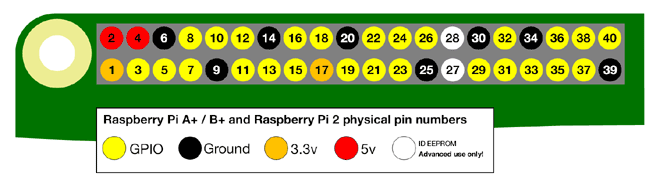
There are 40 GPIO output pins in Raspberry Pi 2. But out of 40, only 26 GPIO pins (GPIO2 to GPIO27) can be programmed. Some of these pins perform some special functions. With special GPIO put aside, we have only 17 GPIO remaining. Each of these 17 GPIO pin can deliver a maximum of 15mAcurrent. And the sum of currents from all GPIO Pins cannot exceed 50mA. To know more about GPIO pins, go through: LED Blinking with Raspberry Pi
Components Required:
Here we are using Raspberry Pi 2 Model B with Raspbian Jessie OS. All the basic Hardware and Software requirements are previously discussed, you can look it up in the Raspberry Pi Introduction, other than that we need:
- Connecting pins
- 220Ω or 1KΩresistor (6)
- LED (8)
- 0.01µF capacitor
- 74HC595 IC
- Bread Board
Circuit Diagram:

Shift Register IC 74HC595:
Let’s talk about the PINS of SHIFT REGISTER we are going to use in here.
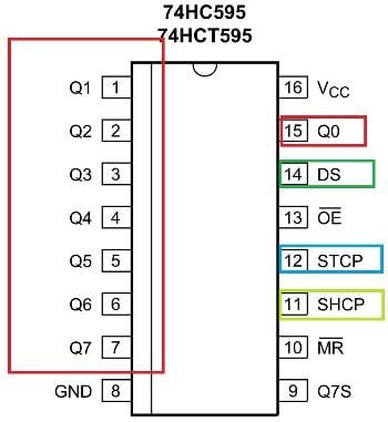
Pin Name | Description |
Q0 - Q7 | They are the output pins (red rectangle), where we get 8 Bit Data parallel. We will connect eight LED to them to see the parallel output. |
Data Pin (DS) | First data is sent bit by bit to this pin. To send 1, we pull-up the DATA pin high and to send 0 we will pull down DATA pin. |
Clock Pin (SHCP) | Every pulse at this pin forces the registers to take in one bit of data from DATA pin and store it. |
Shift Output (STCP) | After receiving 8 bits, we provide pulse this pin to see the output.
|
Flow of Working:
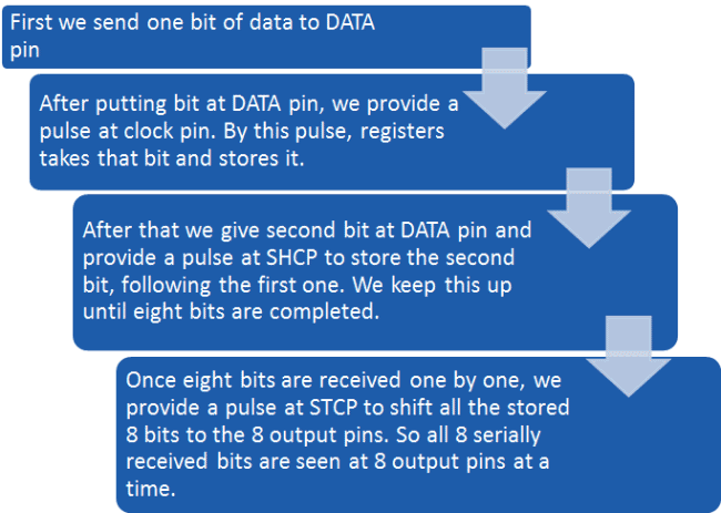
We will follow the Flow Chart and write a decimal counter program in PYTHON. When we run the program, we see LED Counting using Shift Register in Raspberry Pi.
Programming explanation:
Once everything is connected as per the circuit diagram, we can turn ON the PI to write the program in PYHTON.
We will talk about few commands which we are going to use in PYHTON program,
We are going to import GPIO file from library, below function enables us to program GPIO pins of PI. We are also renaming “GPIO” to “IO”, so in the program whenever we want to refer to GPIO pins we will use the word ‘IO’.
import RPi.GPIO as IO
Sometimes, when the GPIO pins, which we are trying to use, might be doing some other functions. In that case, we will receive warnings while executing the program. Below command tells the PI to ignore the warnings and proceed with the program.
IO.setwarnings(False)
We can refer the GPIO pins of PI, either by pin number on board or by their function number. Like ‘PIN 29’ on the board is ‘GPIO5’. So we tell here either we are going to represent the pin here by ‘29’ or ‘5’.
IO.setmode (IO.BCM)
We are setting GPIO4, GPIO5 and GPIO6 pins as output
IO.setup(4,IO.OUT)
IO.setup(5,IO.OUT)
IO.setup(6,IO.OUT)
This command executes the loop 8 times.
for y in range(8):
While 1: is used for infinity loop. With this command the statements inside this loop will be executed continuously.
Further explanation of Program is given in Code Section Below. We have all instructions needed to send data to the SHIFT REGISTER now.
Complete Project Code
import RPi.GPIO as IO         # calling for header file which helps us use GPIO’s of PI
import time                             # calling for time to provide delays in program
IO.setwarnings(False)           # do not show any warnings
x=1
IO.setmode (IO.BCM)        # programming the GPIO by BCM pin numbers. (like PIN29 as‘GPIO5’)
IO.setup(4,IO.OUT)            # initialize GPIO Pins as an output.
IO.setup(5,IO.OUT)
IO.setup(6,IO.OUT)
while 1:                               # execute loop forever
    for y in range(8):            # loop for counting up 8 times
        IO.output(4,1)            # pull up the data pin for every bit.
        time.sleep(0.1)            # wait for 100ms
        IO.output(5,1)            # pull CLOCK pin high
        time.sleep(0.1)
        IO.output(5,0)            # pull CLOCK pin down, to send a rising edge
        IO.output(4,0)            # clear the DATA pin
        IO.output(6,1)            # pull the SHIFT pin high to put the 8 bit data out parallel
        time.sleep(0.1)
        IO.output(6,0)            # pull down the SHIFT pin
    for y in range(8):            # loop for counting up 8 times
        IO.output(4,0)            # clear the DATA pin, to send 0
        time.sleep(0.1)            # wait for 100ms
        IO.output(5,1)            # pull CLOCK pin high
        time.sleep(0.1)
        IO.output(5,0)            # pull CLOCK pin down, to send a rising edge
        IO.output(4,0)            # keep the DATA bit low to keep the countdown
        IO.output(6,1)            # pull the SHIFT pin high to put the 8 bit data out parallel
        time.sleep(0.1)
        IO.output(6,0)

you say 0.01µF capacitor, butwhen i look on ebay there are several different voltages, so which one does this circut need