LED Blinking is a very common and almost first program for every embedded learner or beginner. In which we blink an LED with some delay. So today we are here with the same project, but here we will use an AC bulb instead of a normal LED and will blink an AC bulb. You can also drive into this project of Relay Interfacing with PIC Microcontroller.
Whenever we need to connect any AC Appliance in our embedded circuits, we use a Relay. So in this Arduino relay control tutorial, we will simply learn how to interface a Relay with Arduino. Here, we are not using any Relay Driver IC like ULN2003, and will only use an NPN transistor to control the relay.
Knowing how to control a relay using Arduino is an important skill for anyone who wants to connect AC appliances with microcontrollers. This complete tutorial goes from basic Arduino relay control circuit design to full code, so you can switch appliances safely with low-voltage DC signals to control high-voltage AC.
Table of Contents
What is a Relay and Why Use It with Arduino?
A relay is an electromagnetic switch that allows you to control relay with Arduino by using a small DC to switch much larger AC currents safely. A relay is a bridge between the 5V digital Arduino world and standard household appliances of 120V/240V AC.
Arduino vs Relay Specifications Comparison
| Parameter | Arduino Output | Relay Switching Capacity |
| Voltage | 5V DC | 250V AC / 30V DC |
| Current | 40mA max | 10A max |
| Power | 0.2W | 2500W |
Components Required for Arduino Relay Control Circuit
- Arduino
- 5v or 6v relay
- AC appliance or Bulb
- BC547 transistor
- 1k resistor
- Breadboard or PCB
- Connecting jumper wire
- Power supply
- 1n4007 diode
- Screw terminal or terminal block
Understanding Relay Operation in Arduino Projects
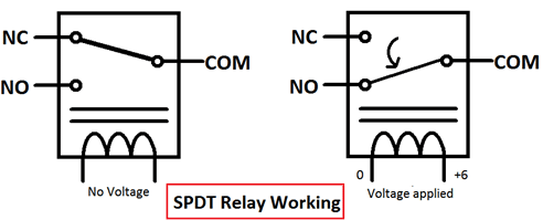
A relay is an electromagnetic switch which is controlled by a small current and used to switch ON and OFF relatively much larger currents. By applying a small current, we can switch ON the relay, which allows a much larger current to flow. A relay is a good example of controlling the AC (alternating current) devices, using a much smaller DC. Commonly used Relay is a Single Pole Double Throw (SPDT) Relay, which has five terminals as follows:

This mechanism enables safe control relay with Arduino for high-voltage applications. When there is no voltage applied to the coil, COM (common) is connected to NC (normally closed contact). When there is some voltage applied to the coil, the electromagnetic field is produced, which attracts the Armature (lever connected to the spring), and COM and NO (normally open contact) get connected, which allows a larger current to flow. Relays are available in many ratings; here we used a 6V operating voltage relay, which allows 7A-250VAC current to flow.
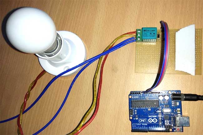
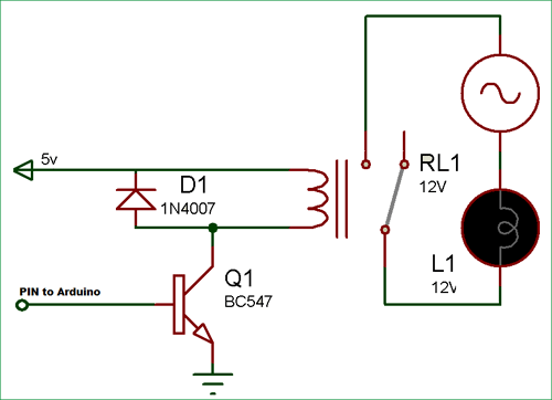
The relay is always configured by using a small Driver circuit which consists of a Transistor, a Diode and a resistor. A transistor is used to amplify the current so that the full current (from the DC source – 9v battery) can flow through a coil to fully energise it. The resistor is used to provide biasing to the transistor. A diode is used to prevent reverse current flow when the transistor is switched OFF. Every Inductor coil produces an equal and opposite EMF when switched OFF suddenly, which may cause permanent damage to components, so a Diode must be used to prevent reverse current. A Relay module is easily available in the market with all its Driver circuits on the board, or you can create it on a perf board or PCB, like below. Here we have used a 6V Relay module.

Here to turn on the Relay with Arduino, we just need to make that Arduino Pin High (A0 in our case) where the Relay module is connected. Below is the Relay Driver Circuit to build your own Relay module:

Complete Arduino Relay Control Circuit Diagram
The Arduino relay control circuit diagram below shows the complete connection between Arduino, relay driver circuit, and AC load.
In this Arduino Relay Control Circuit, we have used Arduino to control the relay via a BC547 transistor. We have connected the transistor base to Arduino pin A0 through a 1k resistor. An AC bulb is used for demonstration. The 12V adaptor is used for powering the circuit.
Arduino Code for Relay On and Off Control
This Arduino code for relay on and off demonstrates basic switching functionality with timed intervals.

Working is simple; we need to make the RELAY Pin (PIN A0) high to make the Relay module ON, and make the RELAY pin low to turn off the Relay Module. The AC light will also turn on and off according to the Relay.
We just programmed the Arduino to make the Relay Pin (A0) High and Low with a delay of 1 second:
void loop()
{
   digitalWrite(relay, HIGH);
   delay(interval);
   digitalWrite(relay, LOW);
   delay(interval);
}
Troubleshooting Arduino Relay Control Issues
| Problem | Possible Cause | Solution |
| Relay doesn't click | Insufficient coil voltage | Check power supply and connections |
| AC load doesn't switch | Wrong terminal connections | Verify COM, NO, NC wiring |
| Arduino resets | Back EMF damage | Add flyback diode across coil |
Technical Summary and GitHub Repository
In the Technical Summary, you’ll find the key principles, circuit details, and project workflow explained. For hands-on experience, the GitHub Repository provides code and resources. This ensures a balance of concept clarity and practical application.
Conclusion
Being able to understand the basics of Arduino relay control is the first step to automating your AC appliances safely with the help of your low-voltage microcontroller. The complete guide outlined the basic circuit information and Arduino relay code to keep in mind for future project applications. Prioritise safety when using AC, make sure to use all protective components, and test your Arduino relay control circuit before deploying it to any real-time applications. The Arduino relay control circuit opens up countless possibilities for home automation and industrial control applications. The techniques and Arduino code for relay on and off operations presented here will serve as your reliable reference guide.
Key Takeaway
» Understand how to design and implement an Arduino relay control circuit diagram
» Learn the complete Arduino code to turn the relay on and off
» Understand the safety procedures to control the AC appliance
» Create real-life projects through a step-by-step process
Demonstration Video and complete code for Arduino Relay Control is given below.
Frequently Asked Questions About Control Relay with Arduino
⇥ 1. Is it possible to directly drive a relay using an Arduino without a transistor?
No, the pins on an Arduino cannot supply more than 40mA of current to power the relay, while most relays require 50-100mA, in which case, we would add a transistor to give additional currents to drive the relay coil for switching purposes without damaging the Arduino.
⇥ 2. Why do you use a flyback diode in Arduino relay driver circuits?
A flyback diode (1N4007) is used to protect against back EMF that occurs when the relay coil is de-energised. Additionally, the absence of it would cause voltage spikes to destroy either or both the transistor and Arduino, with unpredictable behaviour or permanent destruction of the components, along the way.
⇥ 3. Is it safe to use a 3.3V Arduino with a 5V relay module?
Yes, you may need to use level shifters or logic converters. A 3.3V signal will not safely trigger a 5V relay module or circuit. Alternatively, you can use a 3.3V compatible relay module, or you can put a buffer circuit to enable safe switching.
⇥ 4. How many relays can a single Arduino handle at one time?
Arduino Uno contains 14 digital pins and theoretically, 14 relays. Power consumption, processing load, and practical cabling stop this from being the case. For several relays, shift registers, relay drive ICs, or special relay control boards may be considered.
⇥ 5. Why is relay chattering happening in Arduino control circuits?
Chattering occurs from improperly supplied power, faulty connections and/or a voltage drop. Supply a clean 12V supply, proper ground, proper current and check electromagnetic noise from devices around the control circuit.
⇥ 6. What causes relay chattering in Arduino control circuits?
Chattering happens during a faulty power supply, loose or poor connections, or a voltage sag. Apply a good enough 12V power supply, low-resistance green grounding, low-resistance connection channels, and full current supply consideration for electromagnetic interference to and from external equipment to the control circuit.
⇥ 7. Can I use Arduino relays to control inductive loads such as motors?
Yes, but inductive loads cause back EMF and current surges. Use 2-3 times the running current-rated relays, insert snubber circuits between contacts, and include soft-start circuits for big motors to avoid contact welding.
Exploring Relay-Related Projects
Discover more about relay-based applications through the project links provided below.
Relay Interfacing with PIC Microcontroller
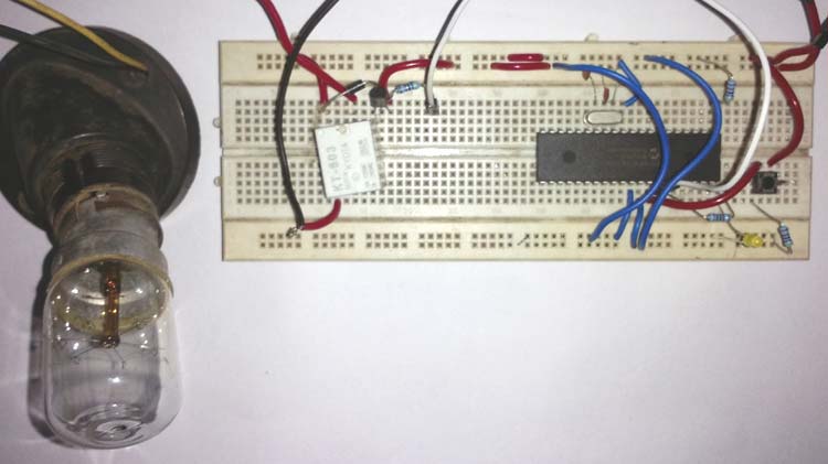
In this project, we will interface a Relay with the PIC Microcontroller PIC16F877A. A relay is a mechanical device to control high voltage, high current appliances ‘ON’ or ‘OFF’ from lower voltage levels. A relay provides isolation between two voltage levels and it is generally used to control AC appliances.
In this blog, we will explore how a relay works, how to interface a single-channel relay with an Arduino Uno, and demonstrate a simple example of how to use the 5V relay module to control a lamp.
Introduction to Relay Logic Control - Symbols, Working and Examples
This extensive guide delves into relay logic control examples, circuit symbols, operation principles, and functional relay logic diagram applications.
Complete Project Code
// Arduino Relay Control Code

#define relay A0
#define interval 1000
void setup() {
  pinMode(relay, OUTPUT);
}
void loop()
{
   digitalWrite(relay, HIGH);
   delay(interval);
   digitalWrite(relay, LOW);
   delay(interval);
}
Comments
Hi,
In arduino we use language indonesian
I Dont Understand
Please replay Again
Thanks You
hi i want to light up a 12 volt LED strip and need to use a uln 2003 a and a 6volt relay and a capacitive sensor to control the light. i.e. when i once touch it it switches on, and when i touch it again it switches off. along with arduino uno. Now i am getting confused as in how shall i used= it. could you be able to help me with this. as i need to add several more componenets in future in order to learn more.
make a circuit diagram Using six switches, three relays, three lights. the lights are energized when the circuit is at rest. activating any of the relays turns all three lights off.
how to get ir sensor on protues software?please give your hand!
dear, friend i need a relay module cod please help me!!!
What do you mean by relay module code? IF you wan to know how to control a relay with Arduino, follow the below tutorial
https://circuitdigest.com/microcontroller-projects/arduino-relay-control


Hi,
in aurduino can we used python language to code?
if possible can u send me the tutorial, to code and how to mention the pin numbers??
please do reply..
thankyou