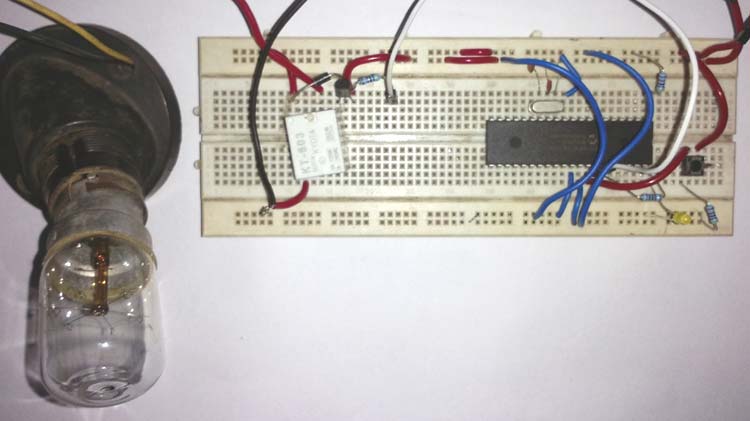
In this project we will interface a Relay with PIC Microcontroller PIC16F877A. Relay is a mechanical device to control high voltage, high current appliances ‘ON’ or ‘OFF’ from lower voltage levels. Relay provides isolation between two voltage levels and it is generally use to control AC appliances. From mechanical to Solid state relays, there are various type of relays are available in electronics. In this project we will use mechanical relay.
In this project we will do the following things-
- We will Interface a switch for input from user.
- Control an 220V AC bulb with 5V relay.
- To control the relay we will use BC547 NPN transistor and the transistor will be controlled from the PIC16F877A. A led will notify the relay ON or OFF condition.
If you are new to PIC Microcontroller then start with Getting Started with PIC Microcontroller.
Component Required:
- PIC16F877A
- 20Mhz Crystal
- 2 pcs 33pF ceramic
- 3 pcs 4.7k resistors
- 1k resistor
- 1 LED
- BC547 Transistor
- 1N4007 Diode
- 5V cubic relay
- AC bulb
- Breadboard
- Wires for connecting the parts.
- 5V Adapter or any 5V power source with at least 200mA current capabilities.
Relay and its Working:
Relay works same as typical switch. Mechanical relays use temporary magnet made from electromagnetic coil. When we provide enough current across this coil, it became energized and pulls an arm. Due to that the circuit connected across the relay can be closed or open. The Input and Output don’t have any electrical connections and thus it isolates input and output. Learn more about relay and its constructions here.
Relays can be found in different voltage ranges like 5V, 6V, 12V, 18V etc. In this project we will use 5V relay as our working voltage is 5 Volts here. This 5V cubic relay is capable to switch 7A load at 240VAC or 10A load at 110VAC. However instead that huge load, we will use a 220VAC bulb and switch it using the relay.
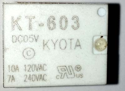
This is the 5V Relay we are using in this project. The current rating is clearly specified for two voltage levels, 10A at 120VAC and 7A at 240VAC. We need to connect load across the relay less than the specified rating.
This relay has 5 pins. If we see the pinout we can see-

The L1 and L2 is the internal electromagnetic coil’s pin. We need to control these two pins for turning the relay ‘ON’ or ‘OFF’. Next three pins are POLE, NO and NC. The pole is connected with the internal metal plate which changes its connection when the relay turns on. In normal condition, POLE is shorted with NC. NC stands for normally connected. When the relay turns on, the pole changes its position and become connected with the NO. NO stands for Normally Open.
In our circuit, we have made the relay connection with transistor and diode. Relay with transistor and diode is available in market as Relay Module, so when you use Relay Module you don’t need to connect its driver circuit (Transistor and diode).
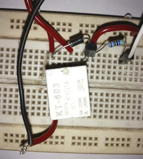
Relay is used in all the Home Automation Projects to control the AC Home Appliances.
Circuit Diagram:
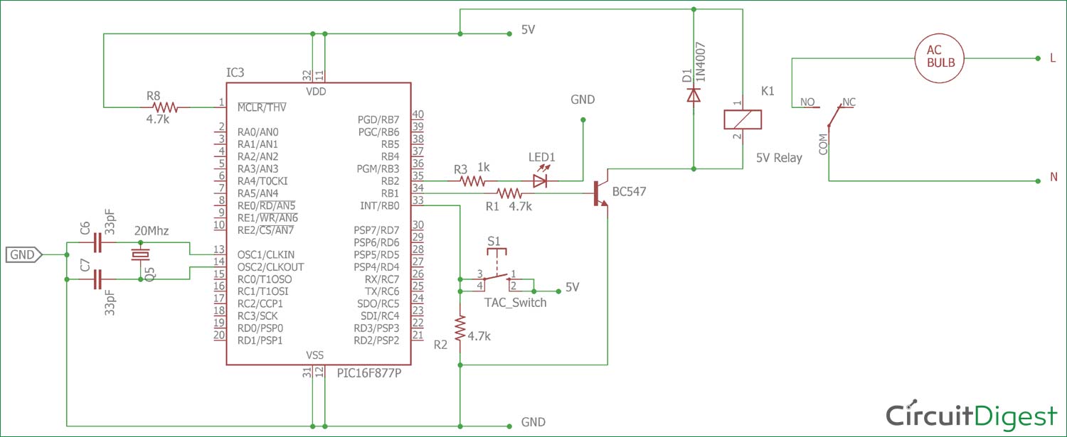
Complete circuit for connecting Relay with PIC Microcontroller is given below:
In the above schematic pic16F877A is used, where on the port B the LED and Transistor is connected, which is further controlled using the TAC switch at RBO. The R1 provide bias current to the transistor. R2 is a pull-down resistor, used across tactile switch. It will provide logic 0 when the switch is not pressed. The 1N4007 is a clamp diode, used for the relay’s electromagnetic coil. When the relay will turned off, there are chances for high voltage spikes and the diode will suppress it. The transistor is required for driving the relay as it requires more than 50mA of current, that the microcontroller is unable to provide. We can also use ULN2003 instead the transistor, it is a wiser choice if more than two or three relays are required for the application, check the Relay module circuit. The LED across port RB2 will notify “relay is on”.
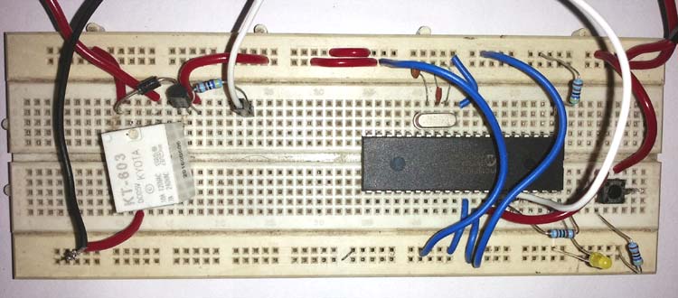
The final circuit will look like this-
You can learn controlling Relay with Arduino here, and if you are really interested in relay then check all the Relay Circuits here.
Code Explanation:
At the beginning of the main.c file, we added the configuration lines for pic16F877A and also defined the pin names across PORTB.
As always first, we need to set the configuration bits in the pic microcontroller, define some macros, including libraries and crystal frequency. You can check code for all those in the complete code given at the end. We made RB0 as input. In this pin the switch is connected.
#include <xc.h>
/*
 Hardware related definition
 */
#define _XTAL_FREQ 200000000 //Crystal Frequency, used in delay
#define SW PORTBbits.RB0
#define RELAY PORTBbits.RB1
#define LED PORTBbits.RB2
After that, we called system_init() function where we initialized pin direction, and also configured the default state of the pins.
In the system_init() function we will see
void system_init(void){
    TRISBbits.TRISB0 = 1; // Setting Sw as input
    TRISBbits.TRISB1 = 0; // setting LED as output
    TRISBbits.TRISB2 = 0; // setting relay pin as output
    LED = 0;
    RELAY = 0;
    }
In the main function we constantly check the switch press, if we detect the switch press by sensing logic high across RB0; we wait for some time and see whether the switch is still pressed or not, if the switch is still pressed then we will invert the RELAY and LED pin’s state.
void main(void) {
    system_init(); // System getting ready
    while(1){
        if(SW == 1){ //switch is pressed
            __delay_ms(50); // debounce delay
            if (SW == 1){ // switch is still pressed
                LED = !LED; // inverting the pin status.
                RELAY = !RELAY;
            }
        }
     }
    return;
    }
Complete code and Demo Video for this Relay interfacing is given below.
Complete Project Code
/*

 * File:   main.c

 * Author: Sourav Gupta

 * By:- circuitdigest.com

 * Created on May 30, 2018, 2:26 PM

 */
// PIC16F877A Configuration Bit Settings
// 'C' source line config statements
// CONFIG

#pragma config FOSC = HS        // Oscillator Selection bits (HS oscillator)

#pragma config WDTE = OFF       // Watchdog Timer Enable bit (WDT disabled)

#pragma config PWRTE = OFF      // Power-up Timer Enable bit (PWRT disabled)

#pragma config BOREN = ON       // Brown-out Reset Enable bit (BOR enabled)

#pragma config LVP = OFF         // Low-Voltage (Single-Supply) In-Circuit Serial Programming Enable bit (RB3/PGM pin has PGM function; low-voltage programming enabled)

#pragma config CPD = OFF        // Data EEPROM Memory Code Protection bit (Data EEPROM code protection off)

#pragma config WRT = OFF        // Flash Program Memory Write Enable bits (Write protection off; all program memory may be written to by EECON control)

#pragma config CP = OFF         // Flash Program Memory Code Protection bit (Code protection off)

#include <xc.h>

/*

 Hardware related definition

 */

#define _XTAL_FREQ 200000000 //Crystal Frequency, used in delay

#define SW PORTBbits.RB0

#define RELAY PORTBbits.RB1

#define LED PORTBbits.RB2
/*

 Other Specific definition

 */

void system_init(void);
void main(void) {

    system_init(); // System getting ready

    while(1){

        if(SW == 1){ //switch is pressed

            __delay_ms(50); // debounce delay

            if (SW == 1){ // switch is still pressed

                LED = !LED; // inverting the pin status.

                RELAY = !RELAY;

            }

        }

     }

    return;

    }


/*

 This Function is for system initialisations.

 */
void system_init(void){

    TRISBbits.TRISB0 = 1; // Setting Sw as input

    TRISBbits.TRISB1 = 0; // setting LED as output

    TRISBbits.TRISB2 = 0; // setting relay pin as output

    LED = 0;

    RELAY = 0;

    }
Comments
I am trying to connect my relay with my fan and its not working.... where should i connect positive,negative wires, and transistor on my relay?



Hi folks, what compiler are you using?, CCS, mplab XC8, MikroC, Hi-tech C?