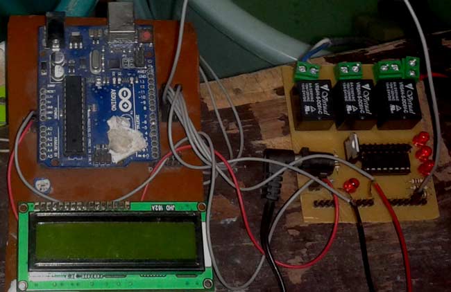
A single-channel relay is an electronic switch that can be controlled by a low-power electrical signal, such as the output from an Arduino microcontroller. By using an Arduino Uno and a single-channel relay module, you can control high-voltage or high-power devices, such as lights, motors, and appliances, from your computer or mobile device. In this blog, we will explore how a relay works, how to interface a single-channel relay with an Arduino Uno, and demonstrate a simple example of how to use the 5v relay module to control a lamp.
Single Channel Relay Module Pinout

VCC - this pin provides power to the module
GND - this is the common ground
IN - This pin is also called the control pin because it is used to control the output of the relay.
COM - is connected to the device you intend to connect.
NC - terminal is connected to the COM terminal by default unless you activate the relay which breaks the connection
NO is normally open unless you activate the relay which then connects it to the COM terminal
NOTE: - In a few generic versions of the relays, the pin sequence could be different. Remember to check the annotations on the PCB or the datasheet before making the connections
Single Channel Relay Module Parts


The construction of a single-channel relay typically consists of the following components:
1. Coil: The coil generates a magnetic field when an electrical current is passed through it, which is used to open or close the switch contacts.
2. Contacts: The contacts are the switching elements of the relay and can be normally open (NO) or normally closed (NC). When the coil is energized, the magnetic field attracts a movable armature, which opens or closes the contacts.
3. Armature: The armature is a movable component that is attracted by the magnetic field generated by the coil. It opens or closes the contacts, depending on the state of the coil.
4. Frame: The frame provides mechanical support for the relay components and protects the relay from external damage.
5. Terminals: The terminals provide a means of connecting the relay to external circuits. The coil is connected to a control circuit, while the contacts are connected to the load.
In addition to these basic components, some relays may also include additional features, such as LED indicators, protection diodes, snubber circuits, or other components to enhance their performance and reliability.
Common questions about Single Channel Relay Module
What is the difference between 1 channel and a 2-channel relay?
A 1-channel relay has a single switch or channel, which means it can only control one load or circuit at a time. This type of relay is typically used in simple applications where only one load needs to be switched, such as turning a single light on or off.
A 2-channel relay, on the other hand, has two switches or channels, which means it can control two separate loads or circuits independently. This type of relay is often used in more complex applications where multiple loads need to be switched, such as controlling two separate lights or motors.
Why are relays used?
Relays are used to switch high power loads using a low power control signal, providing electrical isolation between the control circuit and the load. They are often used to control lights, motors, and other high-power devices, and can be controlled by a variety of signals, such as switches, sensors, or microcontrollers. Relays are also used to switch different loads independently, and to protect sensitive electronic components from high voltages and currents.
What is the difference between SSR and relay?
The main difference between SSRs and relays is that SSRs use solid-state electronics to switch loads, while traditional relays use electromechanical contacts. SSRs provide faster switching speeds, and longer lifespan, and do not produce electrical arcing, but are typically more expensive than traditional relays.
How does a Single Channel Relay work?
“A relay is a simple electrical component that allows you to control a high-power electrical device with a low-power electrical switch.”
Now, what does this really means?
It's like a middleman that acts as an on/off switch for another device.
Think of a relay like a switch that is controlled by electricity. Instead of you physically flipping the switch, an electrical signal does it for you. Here's how it works:
An electrical current flow through the coil of wire around the relay's electromagnet, creating a magnetic field.
This magnetic field attracts the metal armature inside the relay and causes it to move, making contact with a switch.
This switch can then control the flow of electricity to a high-power device, like a light, motor, or heating element.
When the electrical current to the coil is turned off, the magnetic field disappears, and the armature returns to its original position, breaking the connection to the switch.
In this way, a relay acts like a switch that can be controlled remotely. It allows you to control a high-power device with a low-power electrical signal, making it very useful in many applications, such as automotive electronics, home automation, and industrial control systems.
Circuit Diagram of Interfacing Single Channel Relay with Arduino UNO
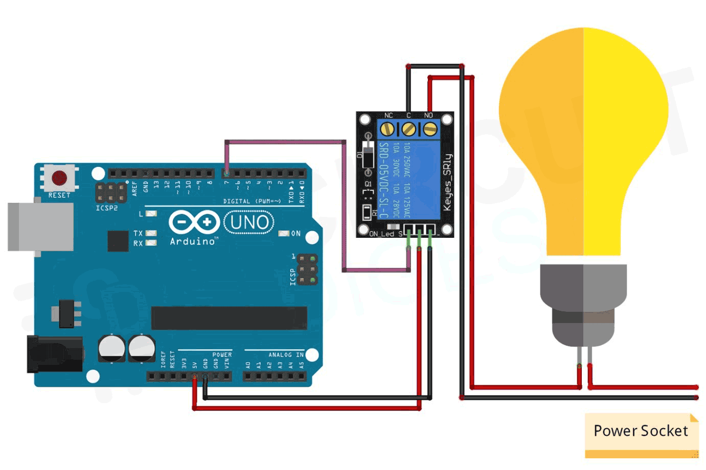
Below is the circuit diagram to control AC appliances using Arduino and relay:
A relay usually has 3 or 4 pins. This relay has 3 pins- VCC, GND and signal
Connect the VCC pin to the 5V pin on the Arduino, the GND pin to a GND pin on the Arduino, and the IN pin to a digital pin on the Arduino.
Arduino Code
Example code of Arduino interfacing with single channel relay module
int relay_pin = 7;
void setup() {
  pinMode(relay_pin,OUTPUT);
}
void loop() {
  digitalWrite(relay_pin,HIGH);
  delay(2000);
  digitalWrite(relay_pin,LOW);
  delay(2000);
}
Explanation of the Code
int relay_pin = 7;
This code sets the variable "relay_pin" to 7, which means that the relay is connected to digital pin 7 on the Arduino Uno.
void setup() {
  pinMode(relay_pin,OUTPUT);
}
In the setup() function, the pinMode() function is used to configure the relay pin as an output, meaning that the pin will be used to send signals to the relay.
void loop() {
  digitalWrite(relay_pin,HIGH);
  delay(2000);
  digitalWrite(relay_pin,LOW);
  delay(2000);
}
In the loop() function, the digitalWrite() function is used to send a digital signal to the relay pin. The first time digitalWrite() is called, it sets the relay pin to HIGH, which turns on the relay. The delay() function is then used to wait for 2000 milliseconds (2 seconds) before turning the relay off by setting the relay pin to LOW. This sequence is repeated continuously in the loop.
In summary, this code alternates the state of the relay every 2 seconds, turning it on and off continuously.
Projects Using Relay module
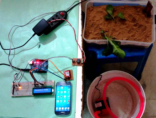
Never forget to water your plants again with this intelligent irrigation system. Using an Arduino microcontroller, moisture sensors, and a relay which controls the water pump, it automatically waters your plants and sends you a text message alert when the soil is dry. Keep your plants healthy and thriving with this easy-to-build DIY project.
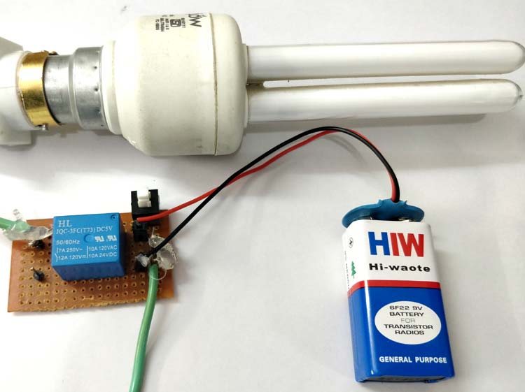
Want to control high-power devices with ease? Add a relay to your circuit! With its ability to switch high voltage and current loads using a low-power signal, the relay is the perfect electronic switch for your project. From controlling lights to motors and more, a relay can handle it all. Learn how to use a relay in your circuit and take your projects to the next level.
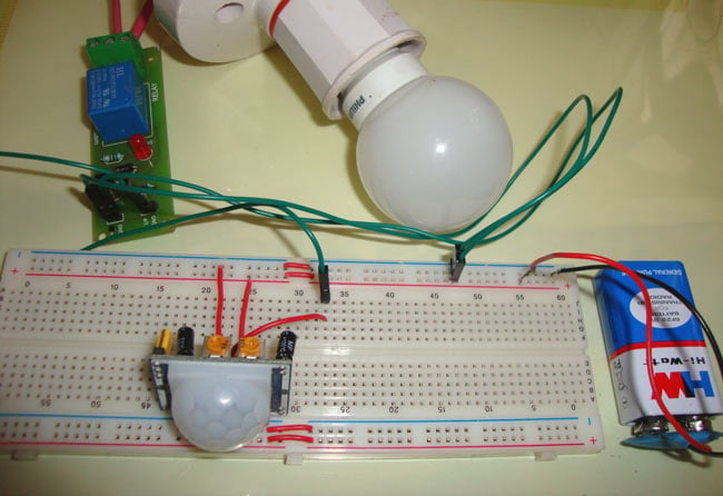
Say goodbye to fumbling for light switches in the dark with this innovative project. Using a PIR sensor and relay, the Automatic Staircase Lights system detects when you enter the staircase and automatically turns on the lights. No more wasted energy and no more tripping in the dark. Bring safety and convenience to your home with this easy-to-build DIY project.
Keep your water tank levels under control with this smart and simple project. By using an Arduino microcontroller, water level sensors, and a water pump, this system automatically monitors and controls the water level in your tank. With real-time level indicators and automated water filling, you'll never have to worry about running out of water again. Build your own Automatic Water Level Indicator and Controller and experience water management made easy.
Complete Project Code
int relay_pin = 7;
void setup() {
  pinMode(relay_pin,OUTPUT);
}
void loop() {
  digitalWrite(relay_pin,HIGH);
  delay(2000);
  digitalWrite(relay_pin,LOW);
  delay(2000);
}

