The main usage of the Relay was seen in the history of transmitting and receiving the information, that was called as Morse code where the input signals used to be either 1 or 0, these change in signals were mechanically noted in terms of ON and OFF of a light bulb or a beep sound, it means those pulses of 1s and 0s are converted as mechanical ON and OFF using electromagnets. Later this was improvised and used in various applications. Let’s see how this electromagnet acts as a switch and why it is named as RELAY.
What is a Relay?
Relay is an electro-mechanically operated switch, however other operating principles are also used in relays, such as solid-state relays. A Relay is generally used when it is required to control a circuit by a separate low-power signal, or when several circuits must be controlled by one signal. They are classified into many types, a standard and generally used relay is made up of electromagnets which in general used as a switch. Dictionary says that relay means the act of passing something from one thing to another, the same meaning can be applied to this device because the signal received from one side of the device controls the switching operation on the other side. So relay is a switch which controls (open and close) circuits electro-mechanically. The main operation of this device is to make or break contact with the help of a signal without any human involvement in order to switch it ON or OFF. It is mainly used to control a high powered circuit using a low power signal. Generally a DC signal is used to control circuit which is driven by high voltage like controlling AC home appliances with DC signals from microcontrollers.
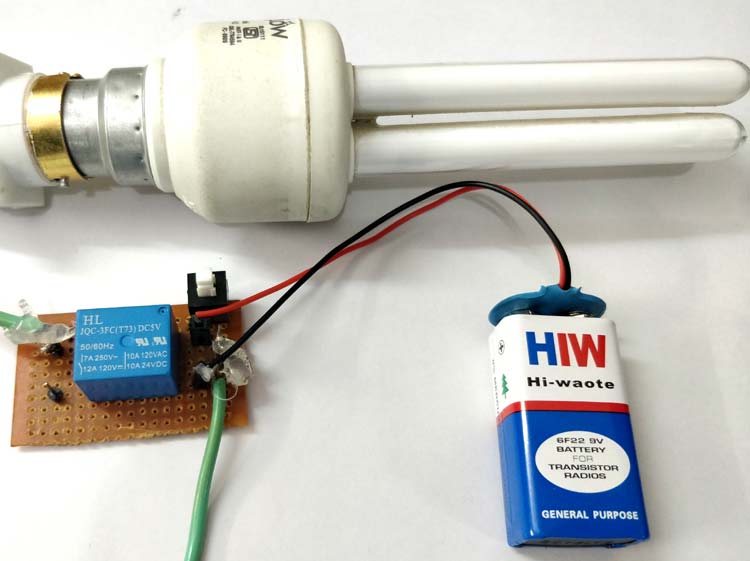
So as of now we understand what is a relay and why they are used in the circuits. Next we will take a simple example where we will be turning on an AC lamp (CFL) by using a relay switch. In this relay circuit we use a push button to trigger a 5V relay, which in turn, complete the second circuit and turn on the lamp.
Material Required
- Relay 5V
- Bulb Holder
- CFL
- Push ON/OFF Button
- Perf-Board
- 9V battery
- AC supply
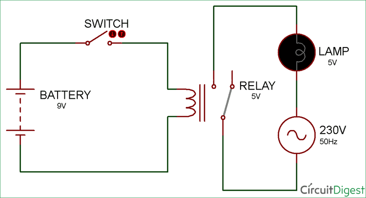
Relay Switch Circuit Diagram
Working of the Basic 5V Relay Circuit
In the above circuit, 5V relay is powered by a 9V battery. An ON/OFF switch is added for the switching purpose of the relay. At the initial condition when switch is open, no current flow through coil, hence Common Port of relay is connected to NO (Normally Open) Pin, so the LAMP remain off.
When the switch is closed, current start flowing through the coil, and by the concept of electromagnetic induction, magnetic field is generated in the coil which attracts the movable armature and the Com Port get connected with NC (Normally Close) pin of the relay. Hence, the LAMP turns ON.
So, by a simple mechanism, controlled by 9V, we can control the AC supply of 230V.


