

Introduction
If you've received the DIY version of LiteWing, follow these simple steps to assemble your drone. No 3D-printed frame or complex tools are required. Everything fits directly into the LiteWing PCB, which also acts as the drone's structural frame. If you are completely new to LiteWing check out the LiteWing Wiki Page or watch this video on what is LiteWing Drone to learn more about our ESP32-based programmable drone development board.
Package Contents
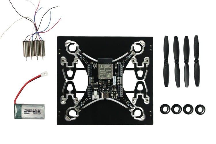
Required Tools and Materials
Assembly Steps
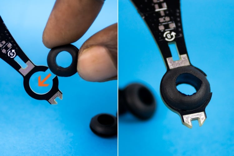
⇒ Step 1: Insert the Rubber Grommets
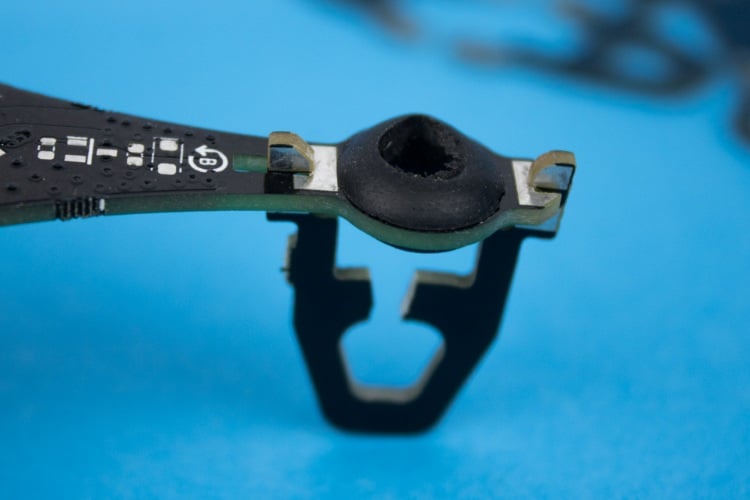
⇒Step 2: Attach the PCB Legs/Stands
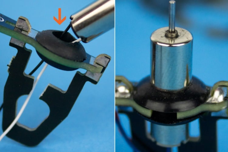
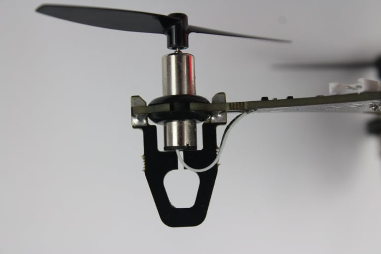
⇒Step 3: Insert Coreless Motors
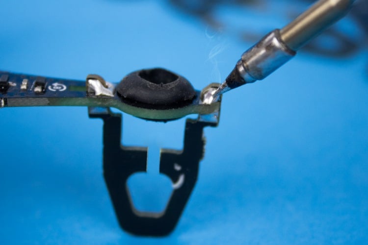
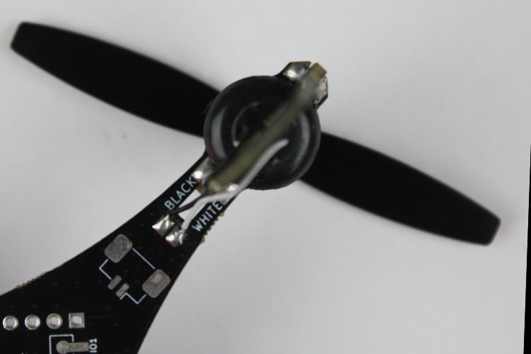
⇒ Step 4: Trim and Solder Motor Wires
⇒ Step 5: Attach the Propellers
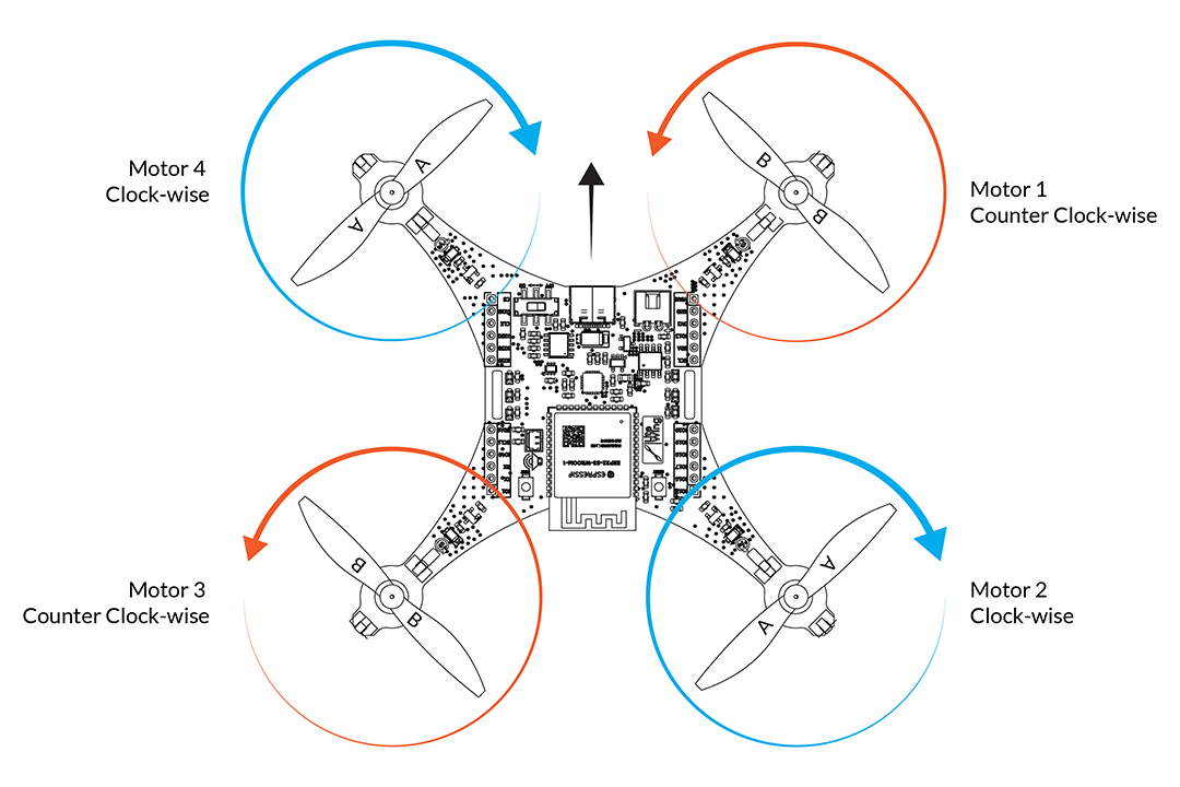
When you receive LiteWing, you will get two sets of propellers (2 CW and 2 CCW). To use the LiteWing, you must fix the four propellers to the correct motors.
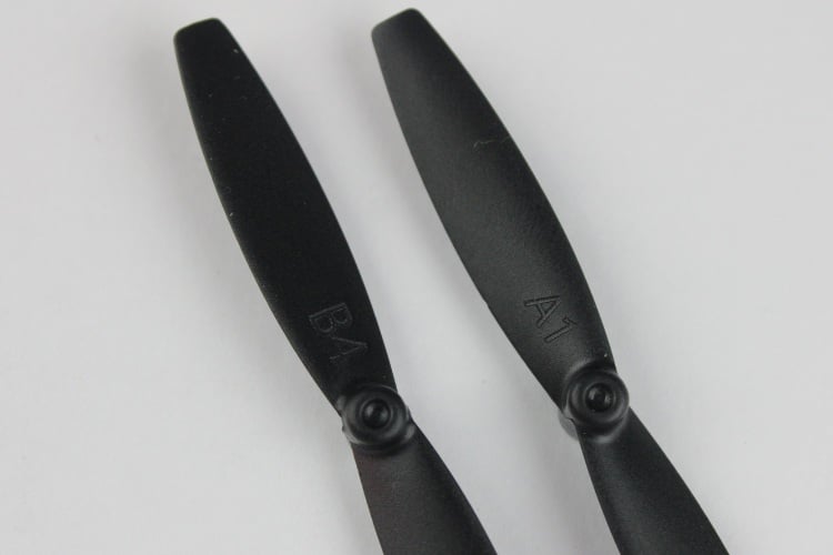
Propeller Markings
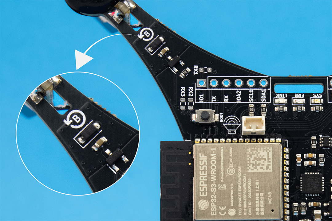
The position where the propellers are installed is critical for proper flight. The corresponding letter and direction of rotation are marked on the PCB near each motor position.
Installation Instructions
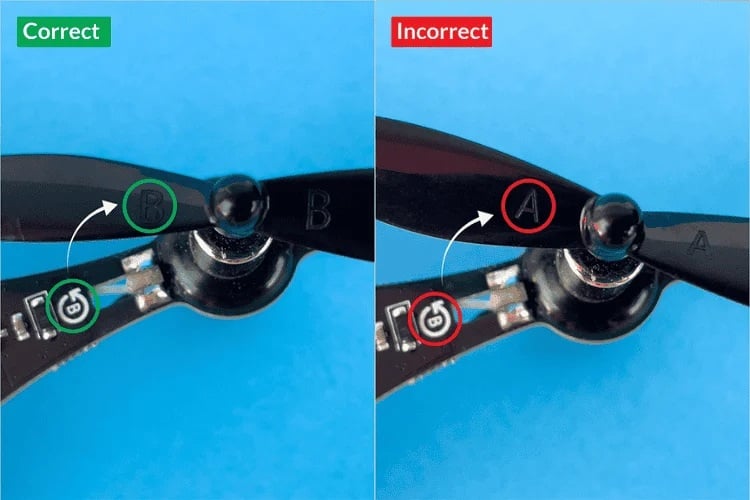
Use the image below to verify both propeller placement and rotation direction during testing:
Correct vs Incorrect Installation:
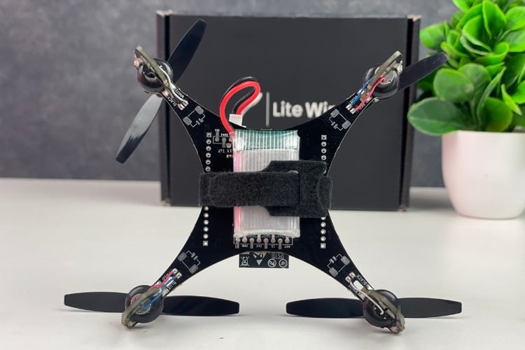
⇒ Step 6: Install the Battery
Tip: See the Battery Selection Guide for battery recommendations.
Assembly Complete!
You're now ready to start flying your LiteWing drone. Make sure to review the preflight check and calibration instructions before your first flight.
Document Index
Last Updated: December 8, 2025 | Build Status: Tested & Verified
You can either attach them to the bottom side, soldering SMD female header.
Should the Optical Flow Sensor be facing down towards the ground? However, if I were to use the SMD method of attachment the pins are mirrored - IF the lens is facing down on the bottom of the drone! Could you provide a picture of the LiteWing with the sensors attached.
I tried to match the pins of the other sensors, with the SMD in mind, and they will not fit on the bottom of the board. The components of the sensors obstruct the connection. Is it possible that the labels on for the SMD points are mirrored or backward? Has anyone else successfully SMDed the sensors? A picture of success would help. I assume that the ToF and Optical Flow sensor are to face the Ground?
If I were to use the headers, I would like to see a picture of where they go.
Use SMD pin headers to attach the sensors. And there are modules with different pinouts are available. Choose the one with the correct pinout
Thank you for the response. It would be very helpful to see a picture and source for the sensors. The ones I chose looked just like the one displayed on your site. Am I correct that the ToF and optical sensors must point down to the earth?
I am hoping that someone has attached the optional sensors successfully on the LiteWing and will be kind enough to help a noobie connect the sensors. Pictures, words, video; anything will be helpful. For some reason I am not seeing how the pins match up, no matter how hard I try!
We are working on a new addon on shild for the LiteWing and will be released soon. Stay tuned.
How do I break the drone PCB? Is there a guide for that?

What about attaching/ soldering the accesory sensors? There are no pins to attach, Assume they are attached like SMD? If so, I have never done that before. Please explain in detail or a short video would be better. I have requested this on the KickStarter page, but no response for a long time. I do no want to waste a drone or the 3 accessories - NOT cheap. THank you!