Introduction
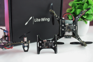
LiteWing is a compact, WiFi-controlled drone based on the ESP32-S3 microcontroller. Designed for hobbyists, makers, and engineers, LiteWing offers a simple yet powerful platform for drone experimentation and development. It is an open-hardware project, making it easy to modify and expand.
Whether you’re new to drones or an experienced developer looking to create custom flight applications, LiteWing provides an accessible and affordable way to explore drone technology. Unlike traditional drones that require proprietary controllers, LiteWing connects to your smartphone, allowing for an intuitive flying experience without additional hardware.
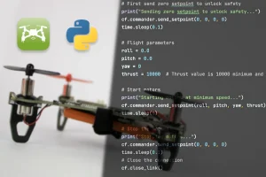
The firmware on LiteWing supports Crazyflie cfclient and cflib, meaning you can program and control your drone using Python and add more features like height hold, position hold, gesture control, and more.
The latest version includes more GPIO pins, sensor mounts, LED indicators to make it easier to tinker with and program. The PCB frame design keeps it lightweight while reducing costs, making it one of the most affordable DIY drones available.

Open Hardware
Fully open-source design with schematics, Gerber & Firmware available for download & modification

Mobile App
Dedicated mobile app for Android and iPhone. No need for an external controller or Joystick

Crazyflie
Comes with modified Crazyflie firmware with support for CFclient and add-on sensor integration

PC Control
Compatible with custom Python SDK (CFlib), allowing you to control the drone with Python scripts

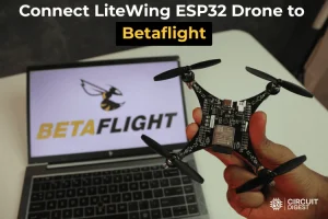
Betaflight
Supports Betaflight, an open-source flight control software for FPV enthusiasts

Arduino
The on-board ESP32-S3 microcontroller can also be programmed using Arduino IDE
Specifications
| Category | Parameter | Specification / Details |
|---|---|---|
| Core System | Microcontroller | ESP32-S3, Dual-core Xtensa LX7, 240 MHz, 512 KB SRAM |
| IMU Sensor | MPU6050 – 3-Axis Gyroscope + 3-Axis Accelerometer | |
| Communication | Wi-Fi 2.4 GHz (CRTP over UDP protocol) | |
| Programming Interface | USB Type-C with CH340 USB-to-UART bridge | |
| Motor & Propulsion | Motor Type | 720 Coreless DC Motors |
| Propeller Size | 55 mm or 65 mm | |
| Motor Control | MOSFET-based PWM speed control | |
| Power System | Battery | 3.7 V 1S Li-Po battery, 20C or higher |
| Charging Circuit | TP4056 Li-ion charging IC (1 A max) | |
| Voltage Regulator | SPX3819, 500 mA low-noise LDO | |
| Physical Specifications | Frame Material | Custom FR4 PCB frame |
| Dimensions | 100 mm × 100 mm | |
| Weight | ~45 g (without battery) | |
| Payload Capacity | ~25 g (with 55 mm propellers) | |
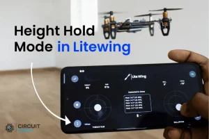
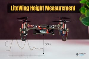
| Optional Sensors | VL53L1X ToF Sensor | Height-hold capability |
| MS5611 Barometric Sensor | Altitude-hold capability | |
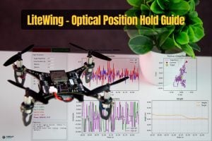
| PMW3901 Optical Flow Sensor | Position-hold capability | |
| Control Options | Mobile Control | Android & iOS app (Wi-Fi based) |
| PC Control | CFClient support and custom Python SDK | |
Quick Start Tutorials
Basic Tutorials

Intermediate Tutorials
Advanced Tutorials
Tutorials using LiteWing Drone Positioning Module
Hardware Overview
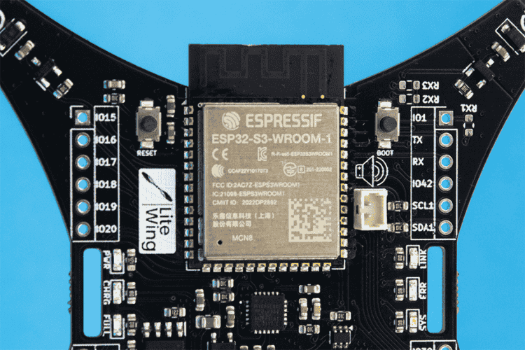
ESP32-S3 Microcontroller
The LiteWing drone is powered by the ESP32-S3, a highly efficient microcontroller that offers low power consumption and an increased number of GPIO pins for enhanced expandability. It is powered by a dual-core Xtensa LX7 core, capable of running at 240 MHz, accompanied by 512 KB of internal SRAM and integrated 2.4 GHz, 802.11 b/g/n Wi-Fi and Bluetooth 5 (LE) connectivity.
Its improved computational efficiency ensures better flight stabilisation and allows seamless future firmware upgrades. The built-in USB interface simplifies programming, debugging, and firmware updates.
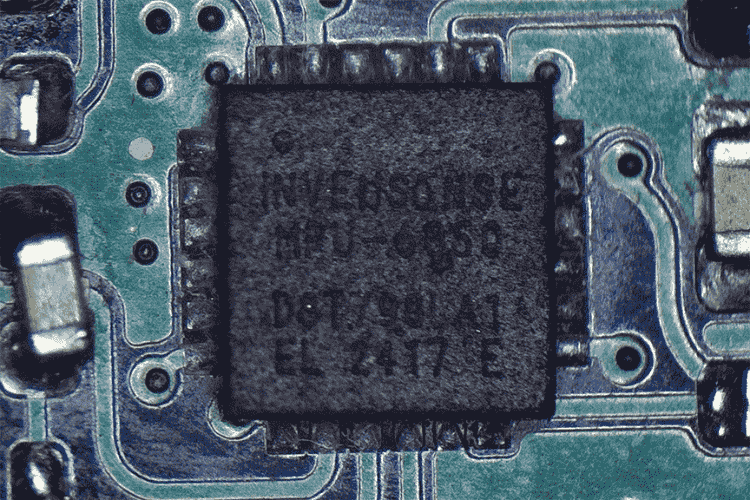
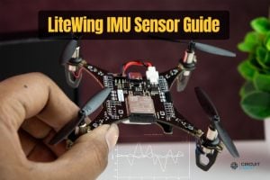
MPU6050 IMU Sensor
For precise flight stability, the LiteWing features an MPU6050 IMU, which provides accurate motion tracking and stabilisation.
Programming Interface
The LiteWing can be easily programmed through the onboard USB Type-C connector without the need for any external programmers or debuggers, thanks to the onboard USB-UART bridge controller and auto-reset circuitry.
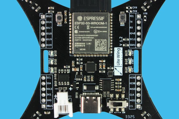
Designed for minimalist efficiency, the LiteWing drone incorporates an all-in-one PCB frame, eliminating the need for additional structural components. The frame includes hook & loop battery strap slots for easy mounting and removal of the battery.
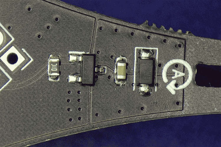
Motor Drivers
The LiteWing employs PWM-based motor control, ensuring smooth acceleration and manoeuvrability with precision. The motor driver circuit is built around an N-channel MOSFET along with a flyback diode and a pull-down resistor.
Power Management
LiteWing features a simple but efficient power management circuit:
| Component | Function |
| TP4056 | Battery charger with up to 1A charging current |
| SPX3819 | Ultra-low-noise 3.3V LDO for ESP32, IMU, and other components |
| Power Path Control | P-Channel MOSFET and Schottky diode for automatic USB/battery switching |
For detailed information on battery selection, see the Battery Selection Guide
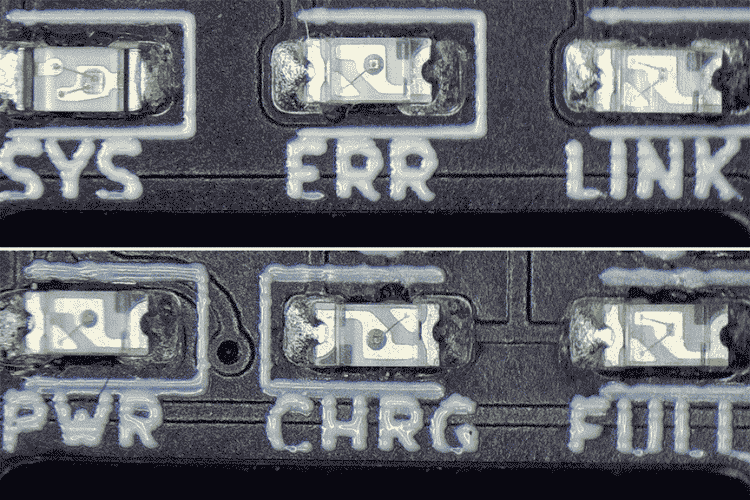
Status & Debugging Indicators
LiteWing features an intuitive LED status system for real-time feedback:
| LED Indicator | Function |
| PWR | Power Indicator. On when LiteWing is turned on. |
| CHRG | Charging Indicator. On when the battery is charging. |
| FULL | Full Charge Indicator. On when the battery is fully charged. |
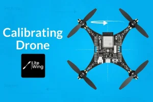
| SYS | System Status. Slow flash indicates sensor calibration; normal flash when ready to fly. |
| ERR | Error Indicator. On when the battery is low. |
| Link | Link Status Indicator. Flashes when connected to the App or PC. |
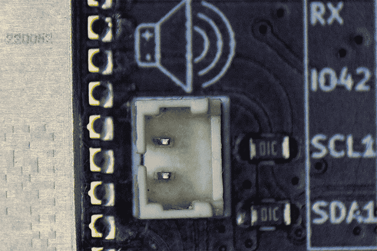
Audio Indicator Option
LiteWing also features an option for audio indications via a 1.25mm pitch JST connector near the ESP32-S3 SoC for connecting a passive piezo buzzer.
Expansion Capabilities
GPIO Expansion Pins
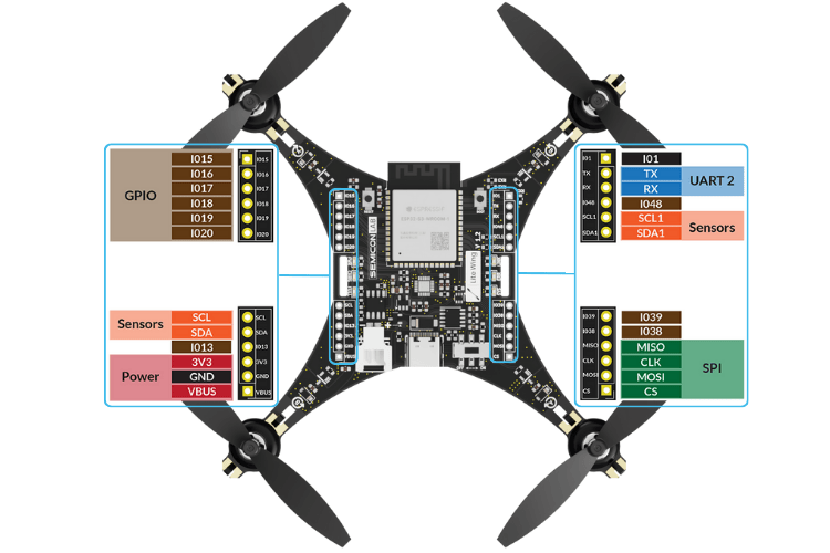
With extra GPIO breakout pins, the LiteWing is designed for expandability, allowing users to integrate additional sensors for enhanced flight capabilities.
| Pin Name | Category | Description / Connection |
|---|---|---|
| IO15 | General GPIO | ESP32-S3 GPIO15 |
| IO16 | ESP32-S3 GPIO16 | |
| IO17 | ESP32-S3 GPIO17 | |
| IO18 | ESP32-S3 GPIO18 | |
| IO19 | ESP32-S3 GPIO19 | |
| IO20 | ESP32-S3 GPIO20 | |
| IO1 | ESP32-S3 GPIO1 | |
| TX | UART0 | UART0 TX – Connected to TXD0 |
| RX | UART0 RX – Connected to RXD0 | |
| IO48 | General GPIO | ESP32-S3 GPIO48 |
| SCL1 | I2C1 (ToF – VL53L1X) | I2C1 Clock – Connected to GPIO41 |
| SDA1 | I2C1 Data – Connected to GPIO40 | |
| SCL | I2C0 (IMU - MPU6050, Barometric - MS5611& Magnetometer - HMC5883) | I2C0 Clock – Connected to GPIO10 |
| SDA | I2C0 Data – Connected to GPIO11 | |
| IO13 | General GPIO | ESP32-S3 GPIO13 |
| 3V3 | Power | 3.3V Regulated Output |
| GND | Ground Connection | |
| VBUS | USB VBUS Power | |
| IO39 | Buzzer | Buzzer + (Connected to GPIO39) |
| IO38 | Buzzer – (Connected to GPIO38) | |
| MISO | SPI (Optical Flow – PMW3901) | SPI MISO – Connected to GPIO37 |
| CLK | SPI Clock – Connected to GPIO36 | |
| MOSI | SPI MOSI – Connected to GPIO35 | |
| CS | SPI Chip Select – Connected to GPIO42 |
Optional Modules for Assisted Flight Control
The firmware is designed with future updates in mind, enabling features such as position hold and altitude hold:
| Module | Interface | Function | Status |
| VL53L1X ToF Sensor | Auxiliary I2C | Height Hold | Tested and working |
| MS5611 Barometer | I2C | Altitude Hold | Coming soon |
| PMW3901 Optical Flow | SPI | Position Hold | Tested and working |
Assisted flight control is currently supported with the LiteWing App and the custom Python SDK. For setup details, see the New Mobile App Guide.
Firmware and Programming
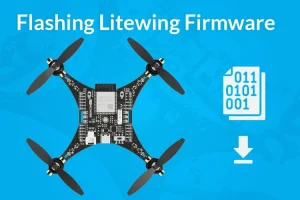
The LiteWing drone firmware is built using ESP-IDF, the official development framework by Espressif for ESP32-series microcontrollers. ESP-IDF provides a set of libraries, drivers, and tools essential for embedded development. Ensure your device is ready for firmware flashing. To flash the latest firmware to your LiteWing drone, you can use the web tool provided here. Click on start flashing and select the correct firmware version for your hardware and confirm that your LiteWing Drone is properly connected via USB and follow the on screen instructions.
Notes:
- Use a supported browser (Chrome / Edge recommended based on chrome v86+).
- Close other applications that may be using the serial port.
- Use a reliable USB cable (data-capable, not charge-only).
- If flashing fails, try reconnecting the device in download mode or lowering the baud rate.
Works entirely in Chrome & Edge.
Firmware Overview
| Framework Feature | Description |
| WiFi & Bluetooth | Built-in support for wireless communication |
| FreeRTOS | Seamless multitasking capabilities |
| Debugging Tools | Performance monitoring and power management |
The LiteWing firmware is based on ESP-Drone, an open-source flight control firmware specifically designed for ESP32-powered drones. ESP-Drone integrates flight control algorithms from the Crazyflie open-source project.
Firmware Components
| Component | Function |
| Flight Control Core | Sensor data processing, stabilization, motor control, PID adjustments |
| Hardware Drivers | Communication with peripherals (I2C, SPI, UART) |
| Communication Modules | Telemetry, remote control, data logging via WiFi |
| Software Libraries | Signal filtering, sensor fusion, real-time data processing |
Programming Options
| Platform | Method | Documentation |
| Python SDK | Crazyflie cflib library | Python Programming Guide |
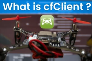
| CFClient | Desktop application for control and monitoring | cfClient Installation Guide |
| Arduino | ESP32-S3 Arduino programming | Coming soon |
CrazyFlie and Python Tutorials
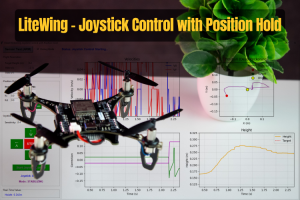
LiteWing comes preloaded with firmware based on ESP-Drone and Crazyflie, making it compatible with cfclient and the cflib Python library. You can control it using an Xbox or PS4/PS5 controller and monitor flight data in real time.
| Tutorial | Description | Link |
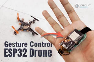
| Gesture Control | Control LiteWing using hand gestures | View Tutorial |
| Python SDK Basics | Getting started with cflib | Python Programming Guide |
Arduino Tutorials
The brain of the LiteWing drone is the ESP32-S3 SoC from Espressif, allowing users to program it from scratch using the Arduino IDE. Basic flight testing with Arduino code and a user-friendly GUI for programming and monitoring has been completed. A step-by-step tutorial on flying LiteWing with Arduino will be available soon.
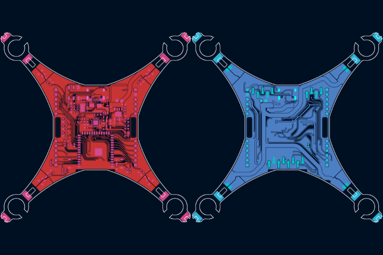
PCB Design & Layout
The hardware design for LiteWing, including the schematics and Gerber files, is made open-source for people to try and experiment. All designs are under a CC license; you are free to build, modify, and share.
| Resource | Description | Link |
| Circuit Diagrams | Circuit Diagrams | GitHub Repository |
| Gerber Files | Gerber Files | GitHub Repository |
| Firmware Binary Source | Firmware Binary Source | GitHub Repository |
Interactive BOM
Circuit Diagram
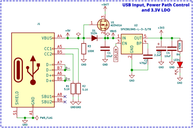
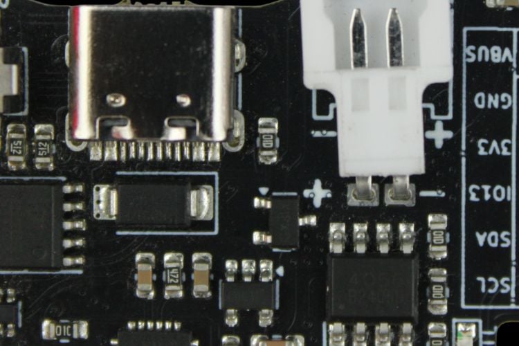
USB Input and Power Path Control
A Type-C USB port is used for both charging and programming purposes. The pull-down resistor on the CCx lines ensures that the LiteWing can be charged or programmed from any standard USB-A or USB-C port.
The power from the USB port is connected to a power path controller circuit built around a P-Channel MOSFET (U1) and a Schottky diode (D1). When USB power is available, the device will be powered from the USB and will also charge the internal battery. When USB power is not present, the device will automatically switch to battery power.
ltage regulation, the design uses a SPX3819 3.3V LDO from Maxlinear, which is capable of providing up to 500mA of current with a very low dropout voltage of 550mV even at full load.
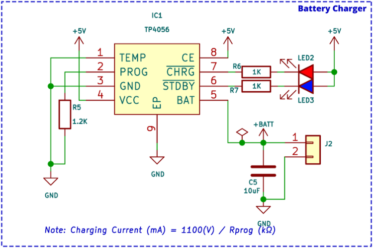
Battery Charger Circuit
The internal battery is charged using the TP4056 charge controller IC, which is capable of a maximum charge current of 1A. The charge current can be adjusted by changing the value of the current programming resistor R5.
The TP4056 provides two charge status indicator outputs: one for charging and one for charge completion. Both outputs are connected to LED indicators for visual feedback. The IC also features a battery temperature monitoring option, though this feature is not utilised in the current circuit design.
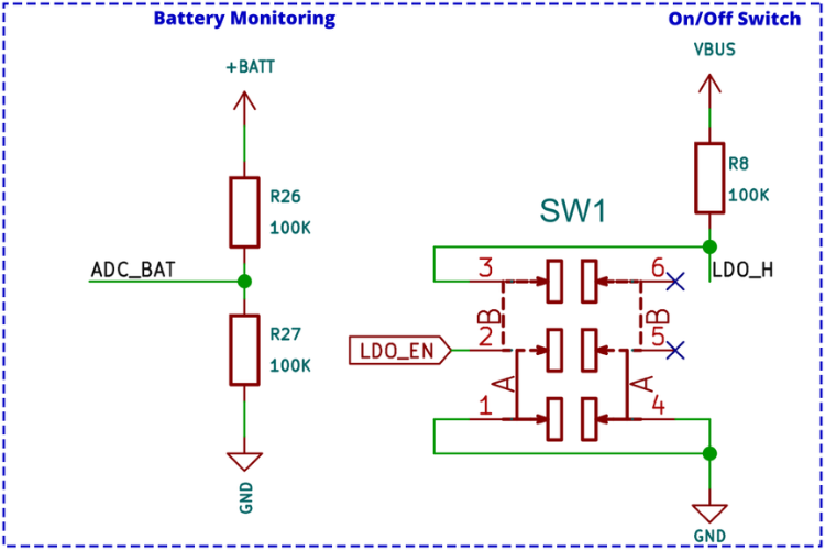
Battery Monitoring and Power Switch
Battery voltage sensing uses a classic voltage divider circuit that reduces the battery voltage to a safe level for measurement. The output from the voltage divider connects to an ADC input of the ESP32, which continuously monitors battery voltage levels.
A slide switch controls the on/off state of the LiteWing. The switch, with a pull-up resistor, connects to the enable pin of the SPX3819 LDO. When this pin is pulled to ground, the LDO shuts down, powering off all components except the battery charging section.
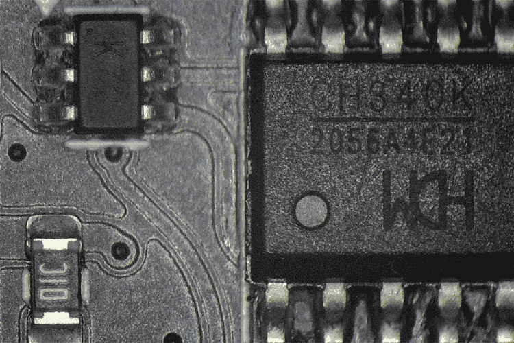
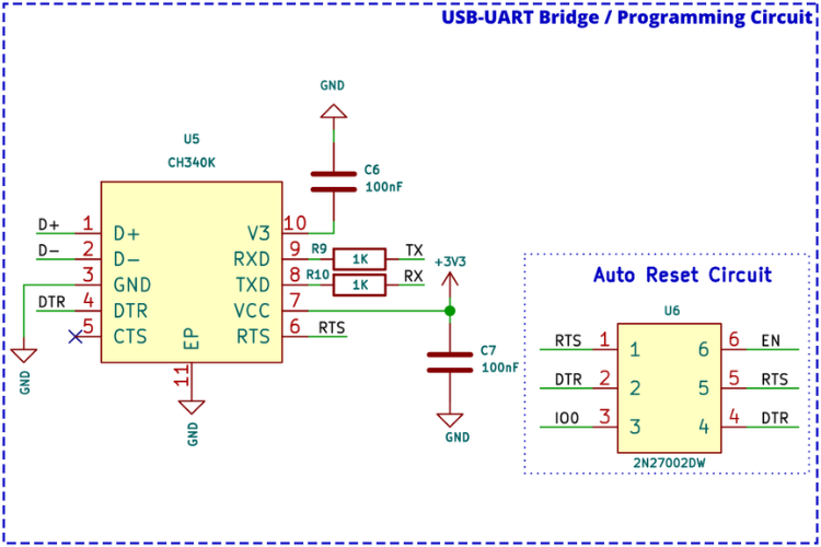
USB to UART Programming Circuit
Although the ESP32-S3 has native USB support, the design includes an external USB to UART bridge for firmware flashing. The CH340K USB to UART bridge controller from WCH provides the following features:
| Feature | Description |
| Interface | Hardware full-duplex UART |
| Buffer | Integrated transmit-receive buffer |
| Baud Rate | 50bps to 2Mbps |
| Oscillator | Integrated crystal oscillator |
For auto-reset functionality, a 2N7002DW dual N-channel MOSFET in a single package reduces component
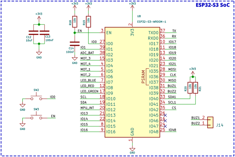
ESP32-S3 Microcontroller Schematic
The ESP32-S3 module section includes manual reset and boot buttons for easier operation and debugging. All connections are labelled, and apart from two strapping pins and one normal GPIO, all other pins are either used for LiteWing functionality or brought out as expansion ports.
A two-pin connector near the module supports a small piezo buzzer for audio output. Standard bypass capacitors and pull-up resistors required by the ESP32-S3 module are also included.
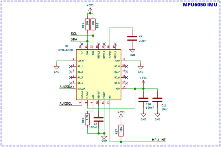
MPU6050 IMU Schematic
The MPU6050 provides 6-axis motion tracking with an integrated 3-axis gyroscope and 3-axis accelerometer. This sensor is essential for maintaining stability, detecting orientation changes, and responding to flight movements in real time.
| Function | Description |
| Communication | I2C interface with ESP32 |
| Processing | Raw sensor data for attitude estimation |
| Integration | Works with PID controller for motor speed adjustment |
| Calibration | Required to minimize drift and improve flight accuracy |
In the LiteWing firmware, the MPU6050 works alongside the flight control core to adjust motor speeds based on pitch, roll, and yaw readings
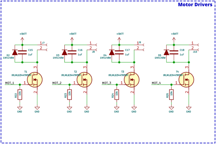
Motor Driver Circuit Schematic
Each motor driver consists of an IRLML6344 N-Channel MOSFET, a flyback diode, and a pull-down resistor. There are four identical circuits, one for each motor.
| Component | Function |
| N-Channel MOSFET | Controls motor on/off state via gate signal |
| PWM Signal | Controls motor speed by varying duty cycle |
| Flyback Diode | Prevents damage from back EMF during switching |
| Capacitors | Suppress voltage spikes for stable operation |
When a high signal is applied to the MOSFET gate, it turns on and allows current to flow, powering the motor.
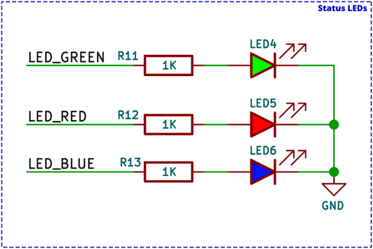
Status LED Schematic
Three debugging LEDs are included in addition to the power and charging indicators:
| LED Color | Behavior | Meaning |
| Green | Slow blink | Sensor calibration in progress |
| Green | Fast blink | System ready for takeoff |
| Blue | Blinking | UDP connection established with controller app |
| Red | Continuous | Battery voltage below safe threshold |
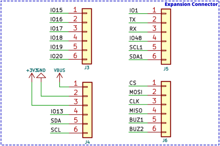
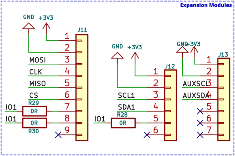
Expansion Connector Schematic
Four expansion connectors provide a total of 24 pins for extending functionality:
| Pin Category | Pins Available |
| Power | VBUS, +3.3V, GND |
| Communication | UART, I2C, Auxiliary I2C, SPI |
| General GPIO | 11 additional pins |
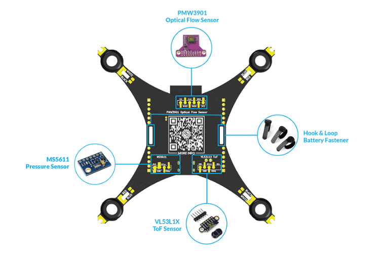
Optional Sensor Module Pads
SMD solder pads on the bottom of the LiteWing PCB enable easy installation of optional sensors for advanced flight modes:
| Sensor | Interface | Function |
| VL53L1X ToF | Auxiliary I2C | Height hold |
| MS5611 Barometer | I2C | Altitude hold |
| PMW3901 Optical Flow | SPI | Position hold |
When using these solder pads, the battery may need to be mounted on top of the LiteWing.
Troubleshooting Guide
| Issue | Possible Cause | Solution |
| App Connection Issue | Mobile data interfering | Ensure mobile data is off and WiFi is connected to drone’s hotspot |
| VPN active | Turn off any VPN | |
| Auto network switching | Disable automatic WiFi switching for networks without internet | |
| App glitch | Restart the LiteWing APP | |
| Drone Disconnecting During Takeoff | Insufficient battery power | Use a higher discharge rating battery (e.g., 650mAh 30C). See Battery Guide |
| Not Responding to Controls | Connection issue | Check app connection and LED indicators |
| Sensor Calibration mode active | If SYS LED blinks slowly, place on flat surface and reset | |
| Improper startup | Always place on flat surface before turning on | |
| Drone Not Taking Off Properly | Wrong propeller placement | Verify motor rotation and propeller installation per PCB markings. See Assembly Guide |
| Drone was Unstable / won’t hover straight | IMU Calibration issue | See the Calibration Guide. |
Where to Buy?
LiteWing project is designed and maintained by CircuitDigest under the SemiconLab initiative. You can buy LiteWing Drones from our distributors listed below:

Have any Questions?
Start a Discussion on:
Hi, my name is Ashraf Nehru, I’m an engineer / developer and investor from London. I’m in the process of starting a project to develop a lightweight drone packbe age capable of retrieving small plastic waste from near-remote forested environments (such as the hillstation environments of Mussourie and Dehradun). I’m interested in chatting with you guys to explore the use of your drone as a platform, and just generally to say hi and see how I can be of assistance to you in your project goals. I’m in Chennai for a few days (20-25th Jan) and would love to meet you IRL if you are around.
I’d be most appreciative if you could contact me direct via email.
best
🙂
ash
I have already purchased this LiteWing ESP Drone.
Please help with the following two queries.
1. Provide the purchase link for the following parts, as it is difficult to identify the correct specifications and items from the vendor website.
MS5611 Barometer I2C Altitude hold
PMW3901 Optical Flow SPI Position hold
2. Can we integrate a camera with this drone? Please provide the specification and purchase link for a suitable camera.
Thanks,
Can you please mention your location, so that we can suggest the right purchase link for MS5611 and PMW3901. Do note we have only tested PMW3901 with our drone and MS5611 is a work in progress.
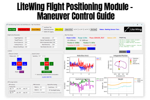
Also, we are soon launching a positioning module as an add-on for LiteWing. More details will be available by mid of FEB.
Camera integration with LiteWing is not possible; the drone has a payload capacity of 40g so you can still use wifi camera modules along with the drone.
I want to connect holybro pmw3901(UART)to the drone, how can it be done, I have tried to integrate however as soon as i connect litewing app the motors start rotating
The problem has been rectified in our latest firwmare. You can follow the below link to download the latest bin files and flash your drone
https://circuitdigest.com/wiki/litewing-drone-positioning-module/#Update_LiteWing_Drone_Firmware_for_Compatibility
Also note that the LiteWing mobile app only supports height hold using ToF for position hold using PMW3901 you would have to use cflib, maybe check out this tutorial
https://circuitdigest.com/microcontroller-projects/litewing-flight-positioning-module-optical-position-hold-guide
Wifi error problem ESP 32 litewing drone
Hii sir help me My Esp32drone error not working see this problem
I bought the drone 5 days before and started testing today. I noticed one of motor is stopping immediately within 5 seconds.
I tried with.
verified directly running motor directly with battery : working
switching motors : Same issue on A2 backside motor drive
can you please help
From what your describing you might have damaged your MOSFET on A2 – IRLML6344TRPBF
hello sir i bought the drone one week ago. To stabilize the drone I add PMW3901 and VL53L1X, can you give me the full code ?
I have this lite wing drone, I connected to my mobile and tried to fly, motors and everything is ok, but it is not flying, movement is there. What is the problem, whether thrust or anything. Please anyone make it clarify.
You shipped your drone with motors that have Red and Blue wires, and WHITE and RED wires. And if you think white and red can be connected like the black and white, incorrect, because you have to connect the white wire to the black terminal, and the red wire to the white terminal for them to spin up CCW (and most likely are driving them the wrong way for the brushes in doing so).
Label your drone with positive and negative instead of wire colors, and do not ship it with any motors if you cant ship it with the correct motors.
its so bad it did not work
Aarav u r so bad ur very bad bad bad bad bad bad bad bad bad bad bad bad
**LiteWing V1.2 Positioning Module Not Detected**
I am using a **LiteWing V1.2 drone with the official positioning module firmware**. The positioning module powers on and its LEDs blink normally, but it is **not detected by either the LiteWing Python library or the mobile app**.
The Python diagnostic output shows:
* **[FAIL] ToF Sensor (VL53L1X) NOT detected**
* **[FAIL] Optical Flow Sensor (PMW3901) NOT detected**
Most of the time the height value is **0.000 m** or unavailable, although very rarely a random height value appears. The X/Y optical flow values never update.
I have already:
* Reflashed the official positioning firmware.
* Reconnected the positioning module multiple times.
* Verified that the module receives power (LEDs blink).
Has anyone faced a similar issue? Could this indicate a faulty positioning module, a connector/I²C/SPI communication issue, or is there anything else I should check?
Hi, Awesome project, I have flashed the firmware and can see the esp (idf.py -p COMX monitor) outputs showing that everything is connected properly, however some of the test appear to be failing as follows:
I (312090) SYS: stabilizerTest = 0
I (312090) SYS: estimatorKalmanTaskTest = 0
I (312090) SYS: soundTest = 0
No one-wire memory handler registered
I (312095) SYS: memTest = 0
I (312598) SYS: pmTest = 1
I (312598) SYS: workerTest = 1
I cannot connect from the litewing app (on andoid or ios) for some reason. I have also tried connecting via cfclient and it says connected but it won’t let me start the motors. Any ideas what could be wrong ?
any help you can provide would be greatly appreciated.
It seems like my MPU6050 is failing self test for some reason. I have tried reading raw values by flashing the esp32-s3 with code to read the raw accellerometer values and the device is connected and I can read the raw values, however the lightwing firmware seems to have trouble passing the mpu6050 self test. Any ideas would be greatly appreciated.
I managed to get it working the mpu6050 was not soldered properly, after checking the soldering carefully I got it working.
On ESP3S drone motor to the left of battery connector (A clockwise) spins on boot but cuts under load, bought the prebuilt off Amazon, is there a fix for this or any way to get it replaced?
The iBOM is not available.
why version 3’s gerber files aren’t available?
Also you have not mentioned different version comparisons.
how can i connect the VL53L1X and what changes will be their in the code. And can i use the Arduino id for it?