

In simple terms, the oscillator is a circuit which converts DC power from the supply source to the AC power to the Load. Oscillator system is built using both active and passive components and it is used for the production of sinusoidal or any other repetitive waveforms at the output without any application of an external input signal. We discussed few oscillators in our previous tutorials:
- Colpitts Oscillator
- RC Phase Shift Oscillator
- Wein Bridge Oscillator
- Quartz Crystal Oscillator
- Phase Shift Oscillator Circuit
- Voltage Controlled Oscillator (VCO)
Any kind of radio-TV transmitter or receiver or any laboratory test equipment has the oscillator. It is the main component for producing the clock signal. A simple oscillator application can be seen inside a very common device such as a watch. Watches use an oscillator to produce a 1 Hz clock signal.
Oscillators are classified as a sinusoidal oscillator or the relaxation oscillator depending on the output waveform. If an oscillator produces a sinusoidal wave with definite frequency across the output, the oscillator is called a sinusoidal oscillator. The relaxation oscillators provide non sinusoidal waves such as square wave or triangular wave or any similar kind of wave across the output.
Other than the oscillator classifications based on the output signal, Oscillators can be classified using the circuit construction like negative Resistance oscillator, feedback oscillator etc.
The Hartley oscillator is one of the LC type (Inductor-Capacitor) feedback oscillator which is invented in 1915 by the American engineer Ralph Hartley. In this tutorial, we will discuss about the construction and application of Hartley oscillator.
The Tank Circuit
Hartley oscillator is an LC oscillator. An LC oscillator consists of a tank circuit which is an essential part to produce the required oscillation. The tank circuit is using three components, two inductors, and a capacitor. The capacitor is connected in parallel with two series inductors. Below is the circuit diagram of Harley Oscillator:
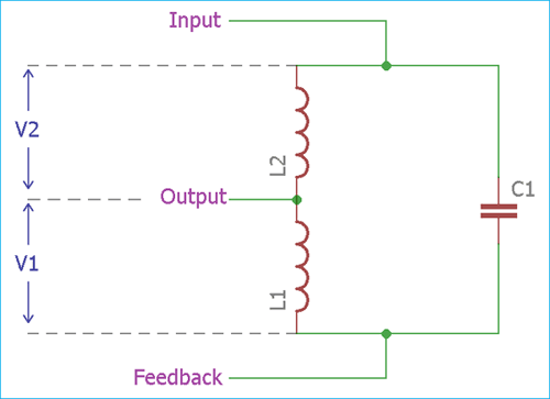
Why the inductor-capacitor combination is called as the tank circuit? Because the LC circuit stores the frequency of the oscillation. In the tank circuit, capacitor and two series inductors are being charged and discharged by each other repetitively which produce an oscillation. The charge and discharge timing or in other words, the value of capacitor and inductors is the main determining factor for the oscillation frequency.
Transistor-based Hartley Oscillator
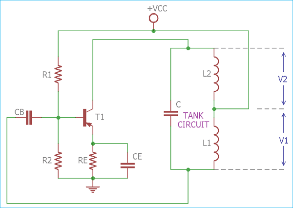
In the above image, a practical Hartley oscillator circuit is shown where an active component is PNP transistor. In the circuit, the output voltage appears across the tank circuit which is connected to the collector. However, the feedback voltage is also a part of the output voltage which is denoted as V1, appearing across the Inductor L1.
The frequency is directly proportional to the ratio of capacitor and inductors values.
Working of Hartley Oscillator Circuit
The active component in Hartley Oscillator is the transistor. The DC operating point in the active region of the characteristics is governed by the resistors R1, R2, RE, and the collector supply voltage VCC. The capacitor CB is the blocking capacitor and CE is Easter bypass capacitor.
The transistor configured in common emitter configuration. In this configuration, the transistor input and output voltage have a 180-degree phase shift. In the circuit, the output voltage V1 and the feedback voltage V2 has 180-degree phase shift. By combing these two, we get a total 360 degree of phase shift, essential for the oscillation (referred to as Barkhausen criterion).
Another essential thing to start the oscillation inside the circuitry without applying an external signal is to produce noise voltage inside the circuit. When the power is switched on, a noise voltage is produced with a wide noise spectrum and it has the required voltage component at the frequency, required for the oscillator.
The AC operation of the circuitry is not affected by the resistance R1 and R2 for a large resistance value. These two resistors are used for the biasing of the transistor. The earth and CE are being used for the immunity of overall circuit and these two resistors and capacitor are used as emitter resistor and emitter capacitor.
The AC operation is largely affected by the resonant frequency of the tank circuit. The frequency of the oscillation can be determined by using the below formula-
F = 1 / 2π√LTC
The total inductance of the tank circuit is LT = L1 + L2
Op-Amp Based Hartley Oscillator
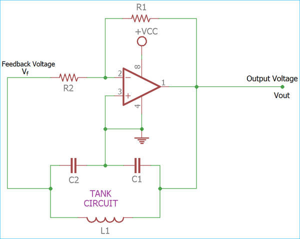
In the above image, the op-amp based Hartley oscillator has been shown where capacitor C1 is connected in parallel with L1 and L2 in series.
The Op-amp is connected in an inverting configuration, where the resistor R1 and R2 is the feedback resistor. The amplifier voltage gain can be determined by the below-mentioned formula –
A = - (R2 / R1)
The feedback voltage and the output voltage is also denoted in the above op-amp based Hartley oscillator circuit.
The frequency of the Oscillation can be calculated using the same formula which is used in transistor based Hartley oscillator section.
Hartley oscillator usually oscillates in the RF range. The frequency can be varied by altering the value of inductor or capacitors or both. For the selection of a variable component, capacitors are chosen above the inductors as they can be easily varied than inductors. The frequency of the oscillation can be changed in the ratio of 3:1 for smooth variations.
Example of Hartley Oscillator
Suppose a Hartley oscillator with a variable frequency of 60-120 KHz consist of a trimmer capacitor (100 pF to 400 pF). The tank circuit has two inductors where the value of one inductor is 39uH. So to find the value of other inductor, we will follow the below procedure:
The frequency of Hartley oscillator is-
F = 1 / 2π√LTC
In this situation where the frequency varies between 60 to 120 kHz which is a 1:2 ratio. The variation of the frequency can be obtained by a pair of coils since the capacitance varies in the ratio of 100pF: 400 pF which is a 1:4 ratio.
So, when the frequency F is 60 kHz, the capacitance is 400 pF.
Now,
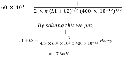
So, the total capacitance is 17.6 mH and the value of other Inductor is
17.6 mH – 0.039 mH = 17.56 mH.
Differences between Hartley Oscillator and Colpitts Oscillator
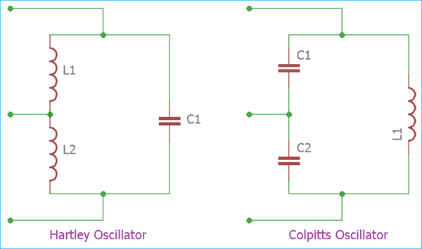
The Colpitts oscillator is very similar to Hartley oscillator but there is a difference in construction between these two. Although Hartley and Colpitts, both oscillators have three components in the tank circuit, the Colpitts oscillator uses a single inductor in parallel with two capacitors in series whereas the Hartley oscillator uses exactly opposite, one single capacitor in parallel with two inductors in series.
Advantages and Disadvantages of Hartley Oscillator
Advantages:
1.The Output amplitude is not proportional with the variable frequency range and the amplitude remains near constant.
2.Frequency is easily controllable using a trimmer instead of the fixed capacitor in the tank circuit.
3.Well suitable for RF range applications due to stable RF frequency generation.
Disadvantages
1.Hartley Oscillator provides a distorted sine wave and not suitable for pure sine wave related operations. The main reason for this drawback is the high amount of harmonics induced across the output.
2.In low frequency the Inductor value become large.
Hartley Oscillator Circuit is mainly used to generate sine wave in various devices like Radio transmitter and receivers.
