

Op-Amp (Operational Amplifier) is the backbone of Analog electronics. An operational amplifier is a DC-coupled electronic component which amplifies Voltage from a differential input using resistor feedback. Op-Amps are popular for its versatility as they can be configured in many ways and can be used in different aspects. An op-amp circuit consists of few variables like bandwidth, input, and output impedance, gain margin etc. Different class of op-amps has different specifications depending on those variables. There are plenty of op-amps available in different integrated circuit (IC) package, some op-amp ic’s has two or more op-amps in a single package. LM358, LM741, LM386 are some commonly used Op-amp ICs. You can learn more about Op-amps by following our Op-amp circuits section.

An op-amp has two differential input pins and an output pin along with power pins. Those two differential input pins are inverting pin or Negative and Non-inverting pin or Positive. An op-amp amplifies the difference in voltage between this two input pins and provides the amplified output across its Vout or output pin.
Depending on the input type, op-amp can be classified as Inverting Amplifier or Non-inverting Amplifier. In previous Non-inverting op-amp tutorial, we have seen how to use the amplifier in a non-inverting configuration. In this tutorial, we will learn how to use op-amp in inverting configuration.
Inverting Operational Amplifier Configuration
It is called Inverting Amplifier because the op-amp changes the phase angle of the output signal exactly 180 degrees out of phase with respect to input signal. Same as like before, we use two external resistors to create feedback circuit and make a closed loop circuit across the amplifier.
In the Non-inverting configuration, we provided positive feedback across the amplifier, but for inverting configuration, we produce negative feedback across the op-amp circuit.
Let’s see the connection diagram for inverting op-amp configuration

In the above inverting op-amp, we can see R1 and R2 are providing the necessary feedback across the op-amp circuit. The R2 Resistor is the signal input resistor, and the R1 resistor is the feedback resistor. This feedback circuit forces the differential input voltage to almost zero.
The feedback is connected across the op-amp’s negative terminal and the positive terminal is connected across the ground. The voltage potential across inverting input is the same as the voltage potential of non-inverting input. So, across the non-inverting input, a Virtual Earth summing point is created, which is in the same potential as the ground or Earth. The op-amp will act as a differential amplifier.
So, In case of inverting op-amp, there are no current flows into the input terminal, also the input Voltage is equal to the feedback voltage across two resistors as they both share one common virtual ground source. Due to the virtual ground, the input resistance of the op-amp is equal to the input resistor of the op-amp which is R2. This R2 has a relationship with closed loop gain and the gain can be set by the ratio of the external resistors used as feedback.
As there are no current flow in the input terminal and the differential input voltage is zero, We can calculate the closed loop gain of op amp. Learn more about Op-amp consturction and its working by following the link.
Gain of Inverting Op-amp
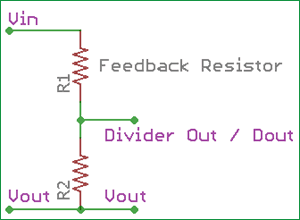
In the above image, two resistors R2 and R1 are shown, which are the voltage divider feedback resistors used along with inverting op-amp. R1 is the Feedback resistor (Rf) and R2 is the input resistor (Rin). If we calculate the current flowing through the resistor then-
i = (Vin – Vout) / (Rin (R2) – Rf (R1))
As the Dout is the midpoint of the divider, so we can conclude
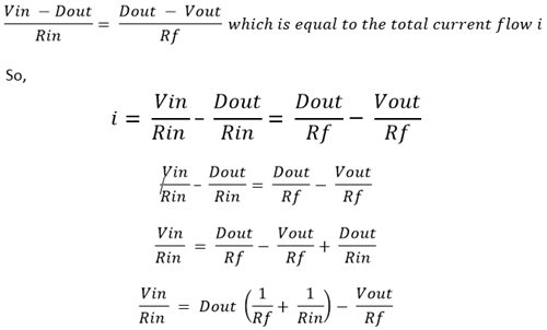
As we described before, due to the virtual ground or same node summing point, the feedback voltage is 0, Dout = 0. So,
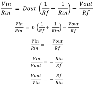
So, the inverting amplifier formula for closed loop gain will be
Gain(Av) = (Vout / Vin) = -(Rf / Rin)
So, from this formula, we get any of the four variables when the other three variables are available. Op-amp Gain calculator can be used to calculate the gain of an inverting op-amp.
As we can see a negative sign in the formula, the output will be 180 degrees out of phase in contrast to the input signal’s phase.
Practical Example of Inverting Amplifier

In the above image, an op-amp configuration is shown, where two feedback resistors are providing necessary feedback in the op-amp. The resistor R2 which is the input resistor and R1 is the feedback resistor. The input resistor R2 which has a resistance value 1K ohms and the feedback resistor R1 has a resistance value of 10k ohms. We will calculate the inverting gain of the op-amp. The feedback is provided in the negative terminal and the positive terminal is connected with ground.
The formula for inverting gain of the op-amp circuit-
Gain(Av) = (Vout / Vin) = -(Rf / Rin)
In the above circuit Rf = R1 = 10k and Rin = R2 = 1k
So, Gain(Av) = (Vout / Vin) = -(Rf / Rin)
Gain(Av) = (Vout / Vin) = -(10k / 1k)
So the gain will be -10 times and the output will be 180 degrees out of phase.
Now, if we increase the gain of the op-amp to -20 times, what will be the feedback resistor value if the input resistor will be the same? So,
Gain = -20 and Rin = R2 = 1k.
-20 = -(R1 / 1k)
R1 = 20k
So, if we increase the 10k value to 20k, the gain of the op-amp will be -20times.
We can increase the gain of the op-amp by changing the ratio of resistors, however, it’s not advisable to use lower resistance as Rin or R2. As the lower value of the resistance lowers the input impedance and create a load to the input signal. In typical cases value from 4.7k to 10k is used for the input resistor.
When high gain requires and we should ensure high impedance in the input, we must increase the value of feedback resistors. But it is also not advisable to use very high-value resistor across Rf. Higher feedback resistor provides unstable gain margin and cannot be an viable choice for limited bandwidth related operations. Typical value 100k or little more than that is used in the feedback resistor.
We also need to check the bandwidth of the op-amp circuit for the reliable operation at high gain.
Summing Amplifier or Op Amp Adder Circuit
An inverting op-amp can be used in various places like as Op amp Summing Amplifier. One important application of inverting op-amp is summing amplifier or virtual earth mixer.

In the above image, a virtual earth mixer or summing amplifier is shown where an inverted op-amp mixing several different signals across it’s inverting terminal. An inverting amplifiers input is virtually at earth potential which provides an excellent mixer related application in audio mixing related work.
As we can see different signals are added together across the negative terminal using different input resistors. There is no limit to the number of different signal inputs can be added. The gain of each different signal port is determined by the ratio of feedback resistor R2 and the input resistor of the particular channel.
Also learn more about applications of the op-amp by following various op-amp based circuits. This inverting op-amp configuration is also used in various filters like active low pass or active high pass filter.
Trans-Impedance Amplifier Circuit
Another use of Op amp inverting amplifier is using the amplifier as Trans-Impedance Amplifier.
In such circuit, the op-amp converts very low input current to the corresponding output voltage. So, a Trans-Impedance amplifier converts current to voltage.
It can convert the current from Photodiode, Accelerometers, or other sensors which produce low current and using the trans-impedance amplifier the current can be converted into a voltage.
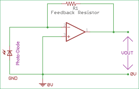
In the above image, an inverted op-amp used to make Trans-Impedance Amplifier which converts the current derived from the photo-diode into a voltage. The amplifier provides low impedance across the photodiode and creates the isolation from the op-amp output voltage.
In the above circuit, only one feedback resistor is used. The R1 is the high-value feedback resistor. We can change the gain by changing this R1 resistor’s value. The high gain of the op-amp uses a stable condition where the photodiode current is equal to the feedback current through the resistor R1.
As we do not provide any external bias across the photo-diode, the input offset voltage of the photodiode is very low, which produce large voltage gain without any output offset voltage. The current of the photo-diode will be converted to the high output voltage.
Other applications of Inverting op-amp are-
- Phase shifter
- Integrator
- In signal balancing related works
- Linear RF mixer
- Various sensors use inverting op-amp for the output.
