
")
Most of the consumer electronic devices around us, such as mobile phones, TVs, Radios, and MP3 players, are a combination of Digital and Analogue electronics. Wherever wireless transmission/reception, or audio signals are involved in an electronic design, we will need periodic oscillating electronic signals. These signals are called Oscillating signals and are very useful in wireless transmission or to perform timing-related operations.
A Voltage Controlled Oscillator is an electronic circuit that generates oscillating signals with frequencies that vary based on the input control voltage. This comprehensive guide explains VCO working principles, circuit design, IC implementations, and real-world applications used by electronics engineers and hobbyists alike.
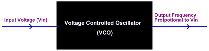
An Oscillator in electronics generally refers to a circuit which is capable of producing waveforms. This waveform can be either of Sine, triangle or even a saw tooth type. Some of the most common oscillator circuits are the LC circuit, the Tank circuit, etc. A Voltage Controlled Oscillator is an oscillator which produces oscillating signals (waveforms) with variable frequency. The frequency of this waveform is varied by varying the magnitude of the Input voltage. For now, you can imagine a Voltage Controlled Oscillator (VCO) to be a black box which takes in a Voltage of variable magnitude and produces an output signal of variable frequency, and the frequency of the output signal is directly proportional to the magnitude of the input voltage. We will learn more about this black box and how to use one in our designs in this tutorial.
Table of Contents
- Understanding the VCO Block Diagram
- Working Principle of Voltage Controlled Oscillator (VCO)
- Types of Voltage-Controlled Oscillators
- Voltage Controlled Oscillator
- Voltage Controlled Oscillator Applications
- What is a Phase Locked Loop (PLL)?
- └ PLL Component Functions
- LM567 Phase Locked Loop IC
- └Frequency Calculation
- └ Circuit Diagram
Understanding the VCO Block Diagram
The voltage controlled oscillator block diagram below shows the essential components:
What is a Voltage Controlled Oscillator?
| Aspect | Details |
|---|---|
| Definition | Electronic circuit producing variable-frequency oscillating waveforms |
| Key Feature | Output frequency controlled by input voltage magnitude |
| Output Types | Sine, triangle, square, or sawtooth waveforms |
| Common ICs | LM566, LM567, LM556 |
| Frequency Range | Hz to GHz depending on implementation |
Working Principle of Voltage Controlled Oscillator (VCO)
A voltage controlled oscillator working principle is straightforward: the input control voltage determines the output signal frequency. There are many types of VCO circuits; a very basic one can be built by just utilising a capacitor, an inductor and a resistor to make a tank circuit. Also, Op-Amps, Multivibrators, transistors, and 555 timers can be utilised to build oscillating circuits. Apart from that, there are dedicated IC packages like LM566, LM567, etc., which can act as a VCO. To understand the basic idea of a VCO, let us consider an RC oscillator.
RC Oscillator Frequency Formula
The simplest voltage controlled oscillator circuit uses an RC (resistor-capacitor) configuration. The frequency in an RC oscillator is calculated using:
In an RC oscillator, the frequency of the output wave depends on the value of the capacitor used in the circuit, since the frequency is given by the formulae
Frequency (f) = 1 / 2πRC
Hence, in this case, the frequency of oscillation is inversely proportional to the value of capacitance used in the circuit. So now to control the output frequency and to make it work as a VCO, we have to vary the capacitance of the Capacitor based on the value of the Input voltage. This can be achieved with the help of varactor diodes. These diodes change the value of capacitance across them based on the voltage applied. A sample output graph of a VCO is shown below.
How Varactor Diodes Enable VCO Circuit Design
This elegant approach enables seamless frequency tuning in a voltage controlled oscillator circuit diagram.
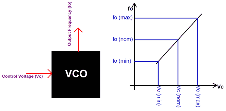
Let us assume the control voltage to be Vc and the output frequency as fo. Then, under normal operating conditions, a nominal voltage is provided to the VCO, for which a nominal Frequency is produced by the VCO. As the input voltage (control voltage) is increased, the output frequency increases, and vice versa is also possible.
Types of Voltage-Controlled Oscillators
There are many types of VCO circuits used in different applications, but they can be broadly classified into two types based on their output voltage.
Harmonic Oscillators: If the Output waveform of the oscillator is sinusoidal, then it is called a harmonic oscillator. The RC, LC circuits and Tank circuits fall into this category. These types of oscillators are harder to implement, but they have better stability than the Relaxation Oscillator. Harmonic oscillators are also called a linear voltage-controlled oscillator.
Relaxation Oscillator: Relaxation oscillators generate non-sinusoidal waveforms (sawtooth or triangular shapes) and represent the easiest path to implementing a voltage controlled oscillator schematic. If the output waveform of the oscillator is in sawtooth or triangular form, then the oscillator is called a Relaxation Oscillator. These are comparatively easy to implement and hence most widely used. Relaxation Oscillator can further be classified as
- Emitter Coupled Voltage Controlled Oscillator
- Grounded Capacitor Voltage Controlled Oscillator
- Delay-based ring Voltage Controlled Oscillator
| VCO Type | Output Waveform | Implementation | Stability | Common Use |
|---|---|---|---|---|
| Harmonic Oscillator | Sinusoidal | RC, LC, Tank circuits | High | RF applications |
| Relaxation Oscillator | Sawtooth, Triangle | Op-Amps, Timers | Moderate | Function generators |
Voltage Controlled Oscillator – Practical Application
As mentioned earlier, VCO can be simply constructed using an RC or an LC pair, but in real-world applications, no one really does that. There is a dedicated IC which can generate oscillations based on the input voltage. One such commonly used IC is the LM566 from National Semiconductor. The LM566 voltage controlled oscillator IC from National Semiconductor is one of the most popular choices for industrial and hobbyist applications.
This IC is capable of generating both triangular and square waves, and the nominal frequency of this wave can be set by using an external capacitor and a resistor. Later, this frequency can also be varied in real time based on the input voltage supplied to it.
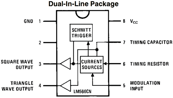
The pin diagram of the LM566 IC is shown below
LM566 Pin Configuration and Function
| Pin | Name | Function | Connection Type |
|---|---|---|---|
| 1 | GND | Ground reference | Power |
| 2 | GND | Ground reference | Power |
| 3 | Square Wave Output | Logic-level square wave | Output |
| 4 | Triangle Wave Output | Triangle waveform (0-Vss) | Output |
| 5 | Control Voltage Input | Tunes output frequency | Input |
| 6 | Timing Capacitor | Sets nominal frequency | Component |
| 7 | Timing Resistor | Sets nominal frequency | Component |
| 8 | Vcc (Positive Supply) | Positive power supply | Power |
The IC can be operated either from a single supply or from a dual supply rail with an operating voltage up to 24V. The pins 3 and 4 are the output pins which give us the Square wave and the Triangle wave, respectively. The Nominal frequency can be set by connecting the right value of the Capacitor and Resistor to the pins 7 and 6.
LM566 Frequency Calculation Formula
To calculate the nominal output frequency for the LM566 voltage controlled oscillator circuit diagram, the output frequency (Fo) is given by the formulae
Fo = 2.4 (Vss - Vc) / Ro+Co+Vss
Where,
Vss is the supply voltage (here 12V), and Vc is the control voltage applied to pin 5, based on whose magnitude the output frequency is controlled. (Here we have formed a potential divider using 1.5k and 10k resistors to supply a constant voltage to pin 5). A sample circuit diagram for LM566 is shown below
LM566 Sample Circuit Diagram
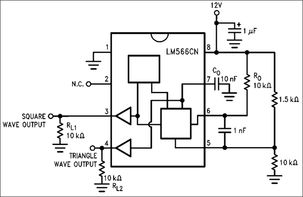
In a practical voltage controlled oscillator schematic, the Resistors 1.5k and 10k can be ignored, and the control voltage can be directly supplied to pin 5. You can also change the value of Ro and Co based on your required range of output frequency. Also, refer to the datasheet to check how linear the output frequency varies with respect to the Input control voltage. The value of output frequency is adjustable using the Control voltage (on pin 5) with a ratio of 10:1, which helps us in providing a wide range of control.
Voltage Controlled Oscillator Applications
Voltage controlled oscillators serve critical functions across multiple electronics domains. Here are the primary voltage controlled oscillator applications:
- Frequency Shift Keying
- Frequency identifiers
- Keypad Tone recognisers
- Clock/Signal/Function Generators
- Used to build Phase Locked Loops.
The voltage-controlled oscillator is the main function block in a locked-loop system. So let us also understand about the Phase Locked Loop, why it is important and what a VCO does inside a Phase Locked Loop.
What is a Phase Locked Loop (PLL)?
A Phase Locked Loop (PLL) is a closed-loop control system that automatically maintains a fixed phase relationship between two signals: an input reference signal and an output signal. Phase Locked Loop, also referred to as PPL, is a control system that mainly consists of three important blocks. They are the Phase Detector, the Low Pass Filter and the Voltage-controlled Oscillator. Together, these three form a control system which constantly adjusts the frequency of the output signal based on the frequency of the input signal. The block diagram of a PLL is shown below
PLL Block Diagram and System Architecture
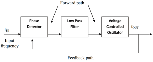
The PLL system is used in applications where a highly stable Frequency (fOUT) has to be obtained from an unstable frequency signal (fIN). The main function of a PLL circuit is to produce the output signal with the same frequency as the input signal. This is very important in wireless applications like Routers, RF transmission systems, mobile networks, etc.
The Phase detector compares the Input frequency (fIN) with the output frequency (fOUT) using the feedback path provided. The difference in these two signals is compared and given in terms of a voltage value, and is referred to as the Error voltage signal. This voltage signal will also have some high-frequency noise coupled with it, which can be filtered by using a low-pass filter. Then this voltage signal is provided to a VCO, which, as we already know, varies the output frequency based on the voltage signal (control voltage) provided.
PLL Component Functions
| Component | Function | Purpose |
| Phase Detector | Compares input and output frequencies/phases | Generates error signal proportional to phase difference |
| Low-Pass Filter | Filters high-frequency noise from error signal | Smooths control voltage, improves stability |
| Voltage Controlled Oscillator | Generates output signal at variable frequency | Adjusts frequency based on filtered error voltage |
LM567 Phase Locked Loop IC: Practical VCO Implementation
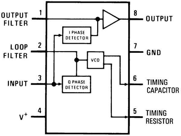
One of the commonly used PLL implementation ICs is the LM567. It is a tone decoder IC, meaning it listens to a particular user-configured type of tone on pin 3. If that tone is received, it connects the output (pin 8) to ground. So basically, to listen to all the sounds available in the frequency range and keep comparing the frequency of those sound signals with a preset frequency using the PLL technique. When the frequencies match, the output pin turns low. The pin of the LM567 IC is shown below. The circuit is highly susceptible to noise, so don’t be surprised if you cannot get this IC to work on a breadboard.
| Pin | Name | Function |
| 1 | Filter Capacitor | External capacitor for noise filtering |
| 2 | Bandwidth Capacitor | Sets detection bandwidth; higher C = narrower bandwidth |
| 3 | Input Signal | Audio or frequency signal to be detected |
| 4 | Ground | Reference ground |
| 5 | Frequency Control Resistor | Part of RC network setting decode frequency |
| 6 | Frequency Control Capacitor | Part of RC network setting decode frequency |
| 7 | Vcc | Positive power supply |
| 8 | Output | Goes LOW when tone frequency is detected |
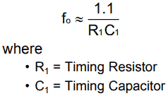
As shown in the pinout, the IC consist of an I and Q Phase detector circuit inside it. These phase detectors check the difference between the set frequency and the incoming frequency signal. External components are used to set the value of this set frequency. The IC also consists of a Filter circuit, which will filter the erratic switching noise, but it requires an external capacitor connected to pin 1. The 2nd pin is used to set the bandwidth of the IC; the higher the capacitance lower the bandwidth. The pins 5 and 6 are used to set the value of the set frequency. This frequency value can be calculated by using the following formulae.
LM567 Frequency Calculation and Setting
LM567 Complete Circuit Diagram
The basic circuit for the LM567 IC is shown below.
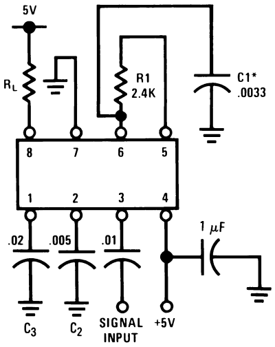
The Input Signal, whose frequency has to be compared, is given to pin 3 through a filtering capacitor of value 0.01uF. This frequency is compared with the set frequency. The frequency is set using the 2.4k Resistor (R1) and 0.0033 Capacitor (C1); these values can be calculated according to your set frequency using the above-discussed formulae.
When the input frequency is matched with the set frequency, the output pin (pin 8) will be grounded. Otherwise, this pin will remain high. Here we have used a Resistor (RL) as a load, but normally it will be an LED or buzzer as required by the design. Thus, the LM567 uses the ability of the VCO to compare frequencies, which is very useful in audio/wireless-related applications. The LM566 voltage controlled oscillator IC from National Semiconductor is one of the most popular choices for industrial and hobbyist applications.
Frequently Asked Questions About Voltage Controlled Oscillators
⇥ 1. What is a voltage-controlled oscillator, and how is it different from a regular oscillator?
The basic function of a voltage-controlled oscillator (VCO), exactly like its name, is to control the output frequency by the level of an input voltage, while non-VCOs perform at a fixed frequency. VCOs can change their frequency during transmission, and that is necessary in communication systems, synthesisers and phase-locked loops where the frequency has to be adjusted in real-time according to either the baseline or user-defined conditions.
⇥ 2. What is a varactor diode, and how is it useful in VCO circuits?
Varactor diodes are semiconductor devices that operate by displaying the capacitance of the junction, which is dependent on the continuously fluctuating reverse bias voltage. Varactor diodes make it possible the electronically tune the frequencies and can be used to replace the variable capacitors that were being operated by manual tuning. The capacitance of the varactor is altered by the control voltage, and consequently, the frequency of oscillation will be different. Thus, it is the case that VCO is modulated with frequency smoothly and accurately.
⇥ 3. What is the difference between harmonic and relaxation oscillators in VCO design?
Harmonic (linear) oscillators generate sine wave outputs and, thanks to LC or tank circuits, have very good frequency stability, and are thus especially suitable for RF (radio frequency) applications. Relaxation oscillators, on the other hand, result in gate/triangular outputs and are easier to design using Op-Amps and timer circuits; however, they do not have as good stability as harmonic ones. The choice between the two oscillator styles depends on the application requirements as to which one would be more advantageous for design.
⇥ 4. What is "frequency sensitivity" or "VCO gain"?
VCO gain (Kv), expressed in units of Hz/Volt, quantifies how much the output frequency changes per unit of control voltage change. With a higher gain, smaller control voltage changes will have a greater impact on how the frequency shifts. VCO gains will typically fall within a range of approximately 100 Hz/V to 1 MHz/V, depending on the circuit and application specifications.
⇥ 5. In what area of application is a voltage-controlled oscillator found in phase-locked loop circuits?
Avoiced-controlled oscillator is in the phase-locked loop circuit, and the output frequency of the circuit, which is being adjusted by the error signal generated from the phase comparator, controls the oscillator. Thus, the output frequency of the VCO is continually adjusted so that the output frequency equals the reference input frequency. The correlation between the VCO frequency and the reference input frequency is the reason for precise frequency tracking in, for example, communication, radio frequency and time synchronisation applications.
⇥ 6. What is an LM567 tone decoder, and how does that device use VCO technology?
The LM567 tone decoder incorporates a complete phase-locked loop (with a VCO) for detecting specific frequencies in audio. The device will compare incoming signals to the reference frequency provided from an outside source, and when the incoming frequency matches, it will forward an output. Also, for tone detection, the next realisation of VCO applications is in the telephone keypad, frequency indicators, and audio filtering in systems.
⇥ 7. What are the main voltage-controlled oscillator applications in present time?
A wide range of important applications of VCOs exist in modern-day electronics as follows: frequency-shift keying modulation, tone detection (keypads on telephones), generating clock/function for test instruments, and audio synthesisers. In addition, voltage-controlled oscillators are present in wireless communications, RF transmission, frequency synthesisers, and timing requirements, which suggest that VCOs play a prominent role in telecommunication, radio, and consumer electronics.
This tutorial was created by the Circuit Digest engineering team. Our experts focus on creating practical, hands-on tutorials that help makers and engineers master Raspberry Pi projects, Electronic Projects, and IoT development projects. Hope you got a good idea about VCOs now.
I hope you liked this article and learned something new from it. If you have any doubts, you can ask in the comments below or use our forum for a detailed discussion.
Related Oscillator-Based Electronics Projects
We’ve previously implemented oscillators in several exciting electronics projects — check out the links below to explore those in detail.

In such a situation, the Quartz Crystal is used. Quartz is a mineral composed of silicon and Oxygen atoms. It reacts when a voltage source is applied to the quartz crystal. It produces a characteristic, identified as the Piezoelectric effect.

In this tutorial, we will learn about the Wein Bridge Oscillator, which was developed by the German physicist Max Wien. It was originally developed for calculating the capacitance where the resistance and the frequency are known.

As we discuss about RC oscillator, and as it is also referred to as a phase shift oscillator, we need a fair understanding of what phase is.

Good and thorough explanation. pls, i want to aask if i can use LM556 for GSM jamming circuit.
Secondly, is there similar tutorial with just transistors?
Thanks