

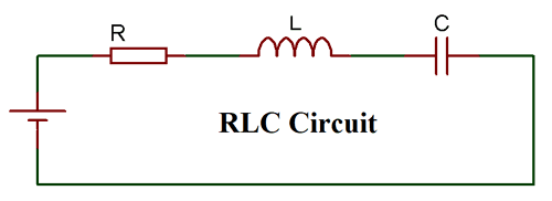
The entire range of electronic components can be divided into two broad categories: active components and passive components. The Passive components include the Resistor (R), the Capacitor (C) and the Inductor (L). These are the three most used components in electronics circuits, and you will find them in almost every application circuit. These three components together in different combinations will form the RC, RL and RLC circuits, and they have many applications such as filtering circuits, Tube light chokes, multivibrators, etc.. So in this tutorial, we will learn the basics of these circuits, the theory behind them and how to use them in our circuits. Understanding RC, RL, and RLC circuits is fundamental for electronics engineering. These three fundamental components form the backbone of RC, RL, and RLC circuits and appear in virtually every electronic application.
Before we jump into the main topics, let's understand what an R, L, and C do in a circuit.
Table of Contents
Core Component Functions in Circuits
⇒ Resistor: Resistors are denoted by the letter “R”. A resistor is an element that dissipates energy mostly in the form of heat. It will have a Voltage drop across it, which remains fixed for a fixed value of current flowing through it.
⇒ Capacitor: Capacitors are denoted by the letter “C”. A capacitor is an element which stores energy (temporarily) in the form of an electric field. A capacitor resists changes in voltage. There are many types of capacitors, out of which the ceramic capacitors and the electrolytic capacitors are mostly used. They charge in one direction and discharge in the opposite direction
⇒ Inductor: Inductors are denoted by the letter “L”. An inductor is also similar to a capacitor; it also stores energy, but it is stored in the form of a magnetic field. Inductors resist changes in current. Inductors are normally coil-wound wire and are rarely used compared to the former two components.
When these resistors, capacitors and Inductors are put together, we can form circuits like RC, RL and RLC circuit, which exhibits time and frequency-dependent responses that will be useful in many AC applications, as mentioned already. An RC/RL/RLC circuit can be used as a filter, oscillator, and much more. It is not possible to cover every aspect in this tutorial, so we will learn the basic behaviour of them.
Fundamental Principles of RC, RL, RLC Circuits
Understanding how resistors, capacitors, and inductors behave in circuits is essential for RC, RL and RLC circuits problem solving. Before we start with each topic, let us understand how a Resistor, a Capacitor and an Inductor behave in an electronic circuit. For understanding, let us consider a simple circuit consisting of a capacitor and a resistor in series with a power supply (5V). In this case when the power supply is connected to the RC pair, the voltage across the Resistor (Vr) increase to its maximum value while the voltage across the capacitor (Vc) stays at zero, then slowly the capacitor starts to build charge and thus the voltage across the resistor will decrease and the voltage across the capacitor will increase until the resistor voltage (Vr) has reached Zero and Capacitor voltage (Vc) has reached its maximum value. The circuit and the waveform can be seen in the GIF below

Circuit Waveform Analysis
The waveform analysis reveals the difference between RC, RL and RLC circuit behaviour. Let us analyse the waveform in the above image to understand what is actually happening in the circuit. A well-illustrated waveform is shown in the image below.

When the switch is turned on, the voltage across the resistor (red wave) reaches its maximum, and the voltage across the capacitor (blue wave) remains at zero. Then the capacitor charges up, and Vr becomes zero and Vc becomes maximum. Similarly, when the switch is turned off, the capacitor discharges, and hence the negative voltage appears across the Resistor, and as the capacitor and resistor discharge, both the capacitor and resistor voltage become zero, as shown above.
The same can be visualised for inductors as well. Replace the capacitor with an inductor, and the waveform will just be mirrored; that is, the voltage across the resistor (Vr) will be zero when the switch is turned on since the whole voltage will appear across the Inductor (Vl). As the inductor charges up the voltage across (Vl), it will reach zero, and the voltage across the resistor (Vr) will reach the maximum voltage.
RC RL RLC Circuits Comparison
| Circuit Type | Components | Time Constant Formula | Primary Applications | Key Characteristic |
| RC Circuit | Resistor + Capacitor | τ = RC | Filters, Timing circuits | Resists voltage changes |
| RL Circuit | Resistor + Inductor | τ = L/R | Chokes, Smoothing circuits | Resists current changes |
| RLC Circuit | Resistor + Inductor + Capacitor | f₀ = 1/(2π√LC) | Oscillators, Resonant circuits | Creates resonance |
RC Circuit:
The RC circuit (Resistor Capacitor Circuit) will consist of a Capacitor and a Resistor connected either in series or parallel to a voltage or current source. These types of circuits are also called RC filters or RC networks since they are most commonly used in filtering applications. An RC circuit can be used to make some crude filters, like low-pass, high-pass and Band-Pass filters. A first-order RC circuit will consist of only one Resistor and one Capacitor, and we will analyse the same in this tutorial

To understand the RC circuit, let us create a Basic circuit on Proteus and connect the load across the scope to analyse how it behaves. The circuit, along with the waveform, is given below
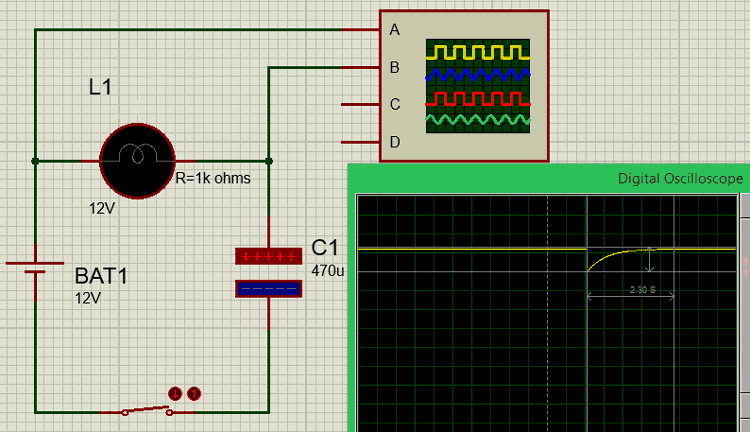
We have connected a load (light bulb) of known resistance 1k Ohms in series with a capacitor of 470uF to form an RC circuit. The circuit is powered by a 12V battery, and a switch is used to close and open the circuit. The waveform is measured across the load bulb and is shown in yellow colour on the image above.
Initially, when the switch is open, maximum voltage (12V) appears across the resistive light bulb load (Vr), and the voltage across the capacitor will be zero. When the switch is closed, the voltage across the resistor will drop to zero, and then as the capacitor charges, the voltage will reach back to maximum as shown in the graph.
RC Circuits Formulas and Calculations
The time taken for the capacitor to charge is given by the formula T = 5Ƭ, where “Ƭ” represents tou (Time constant).
Let us calculate the time taken for our capacitor to charge up in the circuit.
Ƭ = RC
   = (1000 * (470*10^-6))
   = 0.47 seconds
T = 5Ƭ
   = (5 * 0.47)
T = 2.35 seconds.
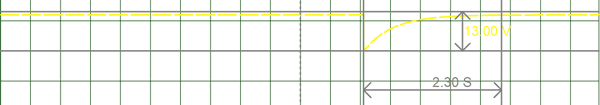
We have calculated that the time taken for the capacitor to charge up will be 2.35 seconds; the same can also be verified from the graph above. The time taken for Vr to reach from 0V to 12V is equal to the time taken for the capacitor to charge from 0V to maximum voltage. The graph is illustrated using the cursors in the image below.
Similarly, we can also calculate the voltage across the capacitor at any given time and the current through the capacitor at any given time using the formulas below
V(t) = VB (1 – e-t/RC)
I(t) =Io (1 – e-t/RC)
Where VB is the battery voltage and Io is the output current of the circuit. The value of t is the time (in seconds) at which the voltage or current value of the capacitor has to be calculated.
RC Circuit Problem Solving Example
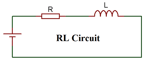
The RL Circuit (Resistor Inductor Circuit) will consist of an Inductor and a Resistor, again connected either in series or parallel. A series RL circuit will be driven by a voltage source, and a parallel RL circuit will be driven by a current source. RL circuits are commonly used as passive filters. A first-order RL circuit with only one inductor and one capacitor is shown below
Similarly, in an RL circuit, we have to replace the Capacitor with an Inductor. The Light bulb is assumed to act as a pure resistive load, and the resistance of the bulb is set to a known value of 100 ohms.
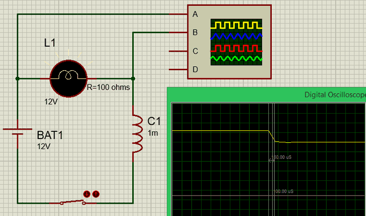
When the circuit is open, the voltage across the resistive load will be maximum, and when the switch is closed, the voltage from the battery is shared between the inductor and the resistive load. The inductor charges up quickly, and hence, a sudden voltage drop will be experienced by the resistive load R.
The time taken for the inductor to charge up can be calculated using the formula T = 5Ƭ, where “Ƭ” represents tou (Time constant).
Let us calculate the time taken for our inductor to charge up in the circuit. Here we have used an inductor of value 1mH and a resistor of value 100 Ohms
Ƭ = L/R
   = (1 * 10^-3) / (100)
   = 10^-5 seconds
T = 5Ƭ
   = (5 * 10^-5)
   = 50 * 10 ^-6
T = 50 u seconds.
Similarly, we can also calculate the voltage across the Inductor at any given time and the current through the Inductor at any given time using the formulas below
V(t) = VB (1 – e-tR/L)
I(t) =Io (1 – e-tR/L)
Where VB is the battery voltage and Io is the output current of the circuit. The value of t is the time (in seconds) at which the voltage or current value of the Inductor has to be calculated.
RLC Circuit
An RLC circuit, as the name implies, will consist of a Resistor, a Capacitor and an Inductor connected in series or parallel. The circuit forms an Oscillator circuit, which is very commonly used in Radio receivers and televisions. It is also very commonly used as a damper circuit in analog applications. The resonance property of a first-order RLC circuit is discussed below
The RLC circuit is also called a series resonance circuit, oscillating circuit or a tuned circuit. This circuit can provide a resonant frequency signal, as shown in the image below
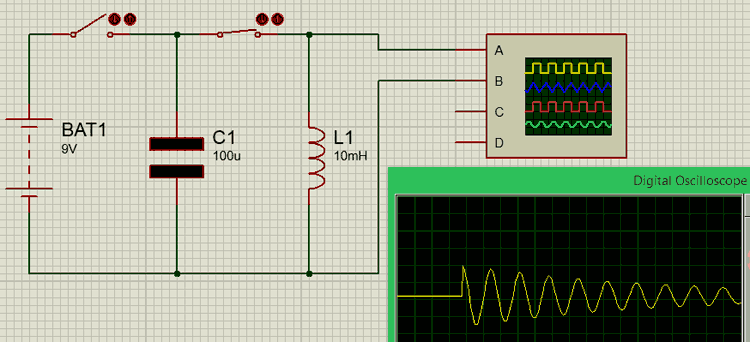
Here we have a capacitor C1 of 100u and an Inductor L1 of 10mH connected in series through a switch. Since the wire that connects the C and L will have some internal resistance, it is assumed that a small amount of resistance is present due to the wire.
Initially, we keep switch 2 open and close switch 1 to charge up the capacitor from the battery source (9V). Then, once the capacitor is charged, switch 1 is opened and then switch 2 is closed.
As soon as the switch is closed, the charge stored in the capacitor will move towards the inductor and charge it up. Once the capacitor is fully discharged, the inductor will start discharging back into the capacitor; this way, charges will flow to and fro between the inductor and the capacitor. But since there will be some loss in charges during this process, the total charge will gradually decrease until it reaches zero, as shown in the graph above.
Key Difference Between RC, RL and RLC Circuits
| Parameter | RC Circuits | RL Circuits | RLC Circuits |
| Energy Storage | Electric field (Capacitor) | Magnetic field (Inductor) | Both electric and magnetic |
| Time Response | Exponential charging/discharging | Exponential current buildup | Oscillatory with damping |
| Frequency Response | Low-pass or high-pass filter | Low-pass or high-pass filter | Band-pass or band-stop filter |
| Phase Shift | 90° (capacitive) | 90° (inductive) | Variable (0° at resonance) |
| Resonance | No resonance | No resonance | Resonant frequency exists |
Applications of RL, RC and RLC Circuits
The versatility of RC, RL, and RLC circuits makes them indispensable in modern electronics. The Resistors, Inductors and Capacitors may be normal and simple components, but when they are combined to form circuits like RC/RL and RLC circuits, they exhibit complex behaviour, which makes them suitable for a wide range of applications. Contemporary applications of RL RC RLC series and parallel circuits are also included. A few of them are listed below
- Communication systems
- Signal Processing
- Voltage/Current magnification
- Radio wave transmitters
- RF amplifiers
- Resonant LC circuit
- Variable tunes circuits
- Oscillator circuits
- Filtering circuits
- 5G Communication systems
- IoT devices
- Medical devices
Understanding RC, RL, and RLC circuits formulas and their applications is essential for electronics engineering success. Whether you're working on RC RL and RLC circuits problem solving or designing new applications, remember that proper analysis requires understanding both time-domain behaviour and frequency response characteristics.
Frequently Asked Questions about RC, RL, and RLC Circuits
⇥ 1. What are the examples of when it would be appropriate to use series versus parallel RC, RL, or RLC circuits?
Series circuits would be used (i.e., filters and timing circuits) where the circuit elements are all carrying the same current. Parallel circuits would be used (i.e., power supplies and impedance matching) where the component circuit elements are all carrying the same voltage. There are advantages and disadvantages to each configuration; the decisions will be based on the desired frequency response and load requirements.
⇥ 2. How do RC circuits work as filters in electronic systems?
RC circuits will create a voltage division that is dependent on frequency. RC low-pass filters will pass low frequencies and attenuate high frequencies; however, RC high-pass filters will pass high frequencies and attenuate low frequencies. In either configuration, the cutoff frequency will be fc=1/(2πRC), which will determine the filter characteristics.
⇥ 3. In what ways do RC and RL circuits differ?
RC circuits use capacitors to store energy in electric fields in order to respond to a voltage change. RL circuits do not store energy in electric fields, but rather in a magnetic field. Inductors help store energy in magnetic fields in order to respond to current change. The time constant for the RC circuit is τ=RC, and the time constant for the RL circuit is τ=L/R.
⇥ 4. Why do RLC circuits oscillate, but RC circuits and RL circuits do not?
The reason RLC circuits oscillate is that they can store energy in an electric field( capacitance) and then a magnetic field (inductance) and have it moving back and forth. In an RC circuit or RL circuit, it just charges or discharges slowly since they didn't have both needed in order to oscillate.
⇥ 5. Why are inductors not used as often as resistors and capacitors?
Inductors are much larger, heavier, more expensive, and have greater parasitic resistance than resistors or capacitors. Inductors will be used only when it is necessary to store energy magnetically or to oppose existing current (as in power supply or RF utilisation).
⇥ 6. What is going on at resonance in RLC circuits?
At the resonant frequency of the circuit, the capacitive reactive and the inductive reactance are balanced (XL=XC) so that only resistance is present in the circuit. In series RLC circuits, this means that maximum current will flow in the circuit, while in parallel RLC circuits, this means maximum impedance across the circuit is present, and frequency operation for the circuit will self-select.
⇥ 7. How does the power factor with AC systems change with RC, RL, and RLC circuits?
RC circuits create a leading power factor (capacitive) and RL circuits create a lagging power factor (inductive). At resonance, RLC circuits can create a unity power factor, and that property is useful to correct the power factor in electrical systems.
Electronics Projects with Circuits
Explore the links below to see how we’ve practically implemented these circuits in our projects.

In simple terms, a voltage regulator minimises the variation in voltage to protect the device. The voltage regulators in an electrical distribution system are located at a substation or in feeder lines.

Capacitor Circuits: Capacitor in Series, Parallel & AC Circuits
So, you know how a capacitor works and what its uses or applications are, but you have to learn how to use a capacitor in electronic circuits.

Inrush Current – Causes, Effects, Protection Circuits and Design Techniques
In this article, we will discuss how to design an inrush current limiter circuit to protect your Power supply designs from inrush currents. We will first understand what inrush current is and the reason why it is generated.
