

We have previously created a complete and detailed tutorial on Phase Shift Oscillator. Here we will see practical implementation of phase shift oscillator. In this project, we create phase shift oscillator circuit on breadboard and test its output using oscilloscope.
What is Phase and Phase Shift?
Phase is a full cycle period of a sinusoidal wave in a 360-degree reference. A complete cycle is defined as the interval required for the waveform to return its arbitrary initial value. Phase is denoted as a pointed position on this waveform cycle. If we see the sinusoidal wave we will easily identify the phase.
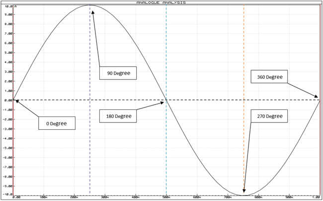
In the above image, a complete wave cycle is shown. The initial starting point of the sinusoidal wave is 0 degree in phase and if we identify each positive and negative peak and 0 points, we will get 90, 180, 270, 360-degree phase. So, when a sinusoidal signal starts it’s journey other than the 0-degree reference, we call it phase shifted differentiating from 0-degree reference.
If we see the next image we will identify how a phase shifted sinusoidal wave look alike…

In this image, there are two AC sinusoidal signal wave presented, the first Green Sinusoidal wave is 360 degree in phase but the red one that is the replica of the first signal, which is 90-degree phase shifted out of the green signal’s phase.
This phase shifting can be done using a simple RC network.
Construction and Circuit
A Phase shift oscillator produces a sine wave. A simple phase shift oscillator is RC oscillator which provides less than or equal to 60-degree phase shift.
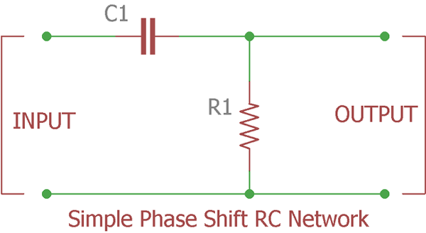
Above image is showing a single pole phase shift RC network or ladder circuit which shifts the phase of the input signal equal to or less than 60 degrees.
If we cascade there RC network, we will get 180-degree phase shift.
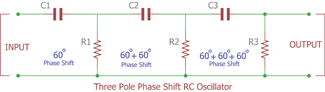
Now to create oscillation and sine wave output we need an active component, either Transistor or Op-amp in inverting configuration, and we need to feed back the output of those components to the input through the three pole RC network. It will produce a 360-degree phase shift at the output and produce a sine wave.
In this tutorial, we will use Transistor as an active element and produce Sine wave through it.
Pre-requisites
To build the circuit we need the following things-
1. Breadboard
2. 3 pcs of .1uF ceramic capacitors
3. 3 pcs of 680R resistor
4. 2.2k resistor 1 pc
5. 10k resistor 1 pc
6. 100R resistor 1 pc
7. 68k resistor 1 pc
8. 100uF capacitor 1 pc
9. BC549 Transistor
10. 9V power supply
Schematic and Working

In the above image, the schematic for Phase Shift Oscillator is shown. We provided the output as the input of the RC-networks which is again provided across the base of the transistor. The RC networks are providing the necessary phase shift in the feedback path which is again altered by the transistor. The frequency of the RC Oscillator can be calculated using this equation-

F is the oscillation Frequency, R and C are the resistance and capacitance, and the N stands for Number of RC phase shift stages used. This formula is only applicable if the phase shift network uses same Resistance and capacitance value, that means R1 = R2 and C1 = C2 = C3. The Phase shift oscillator can be made as variable phase shift oscillator which can produce a wide range of frequencies depending on the pre-set value determined. This can be done easily by changing only the fixed capacitors C1, C2, and C3 with a triple gang variable capacitor. Resistor value should be fixed in such cases.
In the above schematic, the R4 and R5 form a voltage divider which provides a bias voltage to the transistor BC549. The R6 used to limit the collector current and R7 is used for the thermal stability of the BC549 Transistor during operation. C4 is essential as this is the emitter by-pass capacitor of BC549.
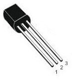
BC549 is an NPN Epitaxial Silicon Transistor. In the above image, the TO-92 package is shown. First pin (1) is the collector, 2 is the Base and 3 is the Emitter pin. It is widely used in switching and amplification purpose. BC549 is from the same segment of widely used 547, 548 etc. BC549 is low noise version. We are using this for our phase shift oscillator’s active component which will amplify and provide an additional phase shift to the signal.
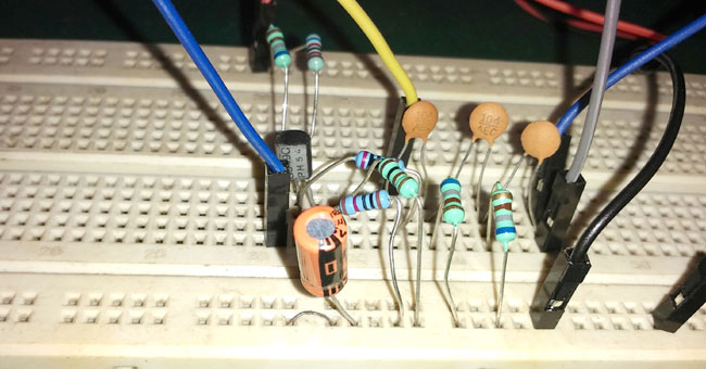
We have constructed the circuit on a breadboard.
Output of Phase Shift Oscillator Circuit
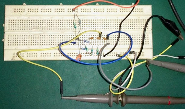
We connected an Oscilloscope across the output to see the sine wave. In the below image we will see our Oscilloscope probe connections.
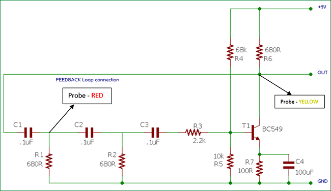
We connected two Oscilloscope probes, Yellow one across the final output and the Red one across second RC network. The yellow channel of the Oscilloscope will provide the result of final output and the Red channel will provide the output across second stage RC filter. By comparing the two outputs we will clearly understand the difference between the two phases of the sine wave. We are powering the circuit from 9V bench power supply unit.
This is the final output from the Oscilloscope.
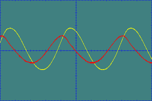
The final output we captured from the Oscilloscope is showing in the above image. The Yellow Sine wave is almost in a phase whereas the Red signal, captured from 2nd stage RC Network is out of the phase. We can see the captured waveform continuously in the below video:
The output is quite stable and the noise interference is lower. Complete Video can be found at the end of this project.
Limitations of Phase Shift Oscillator Circuit
As we are using BJT for phase shift oscillator, there are certain limitations are associated with BJT. The oscillation is stable at low frequencies, if we increase the frequency the oscillation will saturate and the output will be distorted. Also, the output wave amplitude is not so perfect, it will need additional circuitry for stabilizing the amplitude of the waveform circuitry.
Adverse loading effect is also a problem at the RC network stage. Due to the loading effect, the second pole’s input impedance alters the resistance properties of the next preceding first pole filter. Additional filters cascading worsen this effect. Also, due to this reason, it is difficult to calculate the oscillation frequency using standard formula method.
Use of Phase Shift Oscillator Circuit
The main use of a phase shift oscillator is to create sine wave across its output. So, wherever pure sine wave generation is needed, phase shift oscillator is used. Also, for the purpose of phase shifting of a particular signal, the phase shift oscillator provides significant control over the shifting process. Other usages of phase shift oscillators are:
- In audio oscillators
- Sine Wave Inverter
- Voice Synthesis
- GPS units
- Musical Instruments.
If you want to learn more about Phase Shift Oscillator, then follow the link.
