
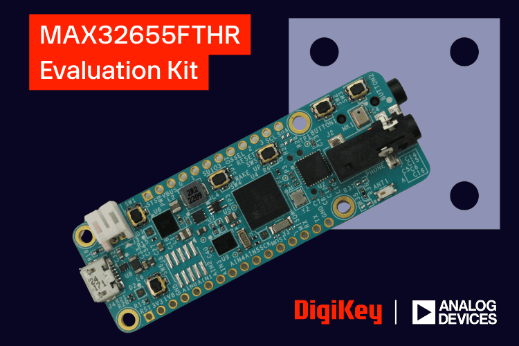
Bluetooth Low Energy (BLE) has become one of the most widely adopted wireless technologies for battery-powered devices, offering reliable communication while consuming only a fraction of the power required by traditional wireless protocols. From wearable electronics and healthcare devices to wireless audio accessories and industrial sensors, BLE enables devices to remain connected for extended periods without sacrificing battery life. To simplify the development of such applications, developers need a platform that combines low-power operation, wireless connectivity, and a rich set of onboard peripherals.
The MAX32655FTHR from Analog Devices is built around the MAX32655 ultra-low-power microcontroller. It features a 100 MHz Arm Cortex-M4F processor with a dedicated RISC-V coprocessor for Bluetooth 5.2 Low Energy, enabling efficient wireless applications with low power consumption. The board also integrates essential peripherals such as a PMIC, audio codec, MEMS microphone, 128 MB QSPI Flash, microSD card slot, and an onboard DAPLink debugger, making it an excellent platform for rapid BLE application development.
CircuitDigest presents Learn, Build & Win by DigiKey. Submit your innovative embedded or electronics project idea for a chance to receive the MAX32655FTHR Evaluation Kit from Analog Devices and bring your project to life.
In this article, we will take a detailed look at the MAX32655FTHR development board, exploring its hardware architecture, onboard peripherals, GPIO pinout, development environment, and software setup. We'll also demonstrate how to get started with the board by setting up the development tools and running your first application, providing a solid foundation for developing low-power Bluetooth-enabled embedded systems.
Development Kit Contents
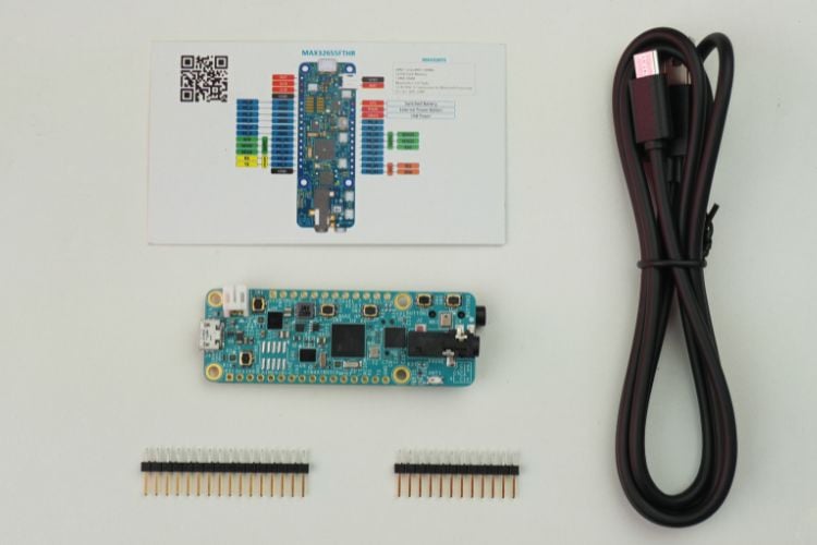
The MAX32655FTHR development kit comes with all the essential accessories required to get started. Inside the box, you'll find the MAX32655FTHR development board, a 16-pin Feather header, a 12-pin Feather header, and a USB-A to Micro-USB cable. The header connectors are provided separately, allowing you to solder them only if needed for your project. The included USB cable is used to power the board, program the firmware, and establish a serial connection with your computer. With these components, the board is ready for evaluation and application development right out of the box.
MAX32655FTHR Dev Board Features
The MAX32655FTHR is a feature-rich development board built around the MAX32655 ultra-low-power microcontroller. In addition to Bluetooth 5.2 connectivity, the board integrates several onboard peripherals including power management, audio hardware, external storage, and debugging circuitry. These features allow developers to quickly prototype and evaluate battery-powered Bluetooth applications without requiring additional hardware.
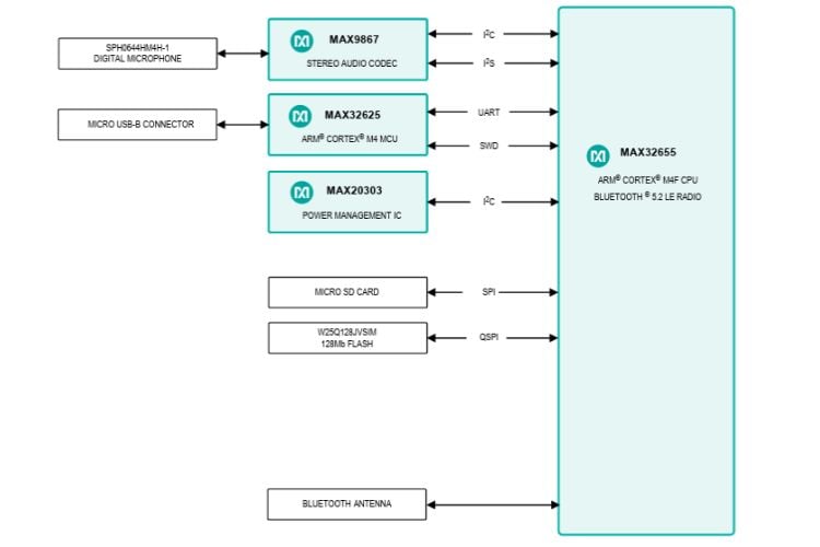
MAX32655 Ultra-Low-Power Microcontroller - At the heart of the board is the MAX32655 microcontroller, featuring a 100 MHz Arm Cortex-M4F processor with a floating-point unit for efficient application processing. A dedicated 32-bit RISC-V coprocessor independently handles the Bluetooth 5.2 Low Energy protocol stack, reducing the workload on the main processor and improving overall power efficiency.
MAX20303 Power Management IC (PMIC) - The onboard MAX20303 PMIC simplifies battery-powered designs by integrating battery charging, voltage regulation, and fuel-gauge functionality into a single chip. It allows the board to be powered directly from a rechargeable Li-Po battery while continuously monitoring battery status.
Audio Codec - The board includes a low-power stereo audio codec that supports high-quality audio playback and recording. Combined with the onboard microphone and headset connector, it enables developers to build voice-enabled applications such as wearable devices, wireless headsets, and audio processing systems without requiring external audio hardware.
Digital MEMS Microphone - An onboard digital MEMS microphone is connected through the I²S interface, making it suitable for applications involving voice commands, audio recording, keyword detection, and sound analysis.
External QSPI Flash Memory - The 128 MB QSPI Flash provides high-speed non-volatile storage for firmware, application assets, configuration data, and Bluetooth resources. Compared to standard SPI Flash, the Quad-SPI interface offers significantly faster data transfers.
MicroSD Card Slot - For applications requiring larger storage capacity, the onboard microSD card slot allows users to store sensor logs, audio recordings, firmware files, and other application data.
Onboard Debugger - Programming and debugging are handled by the integrated DAPLink debugger, eliminating the need for an external programming probe. It also provides a virtual COM port for serial communication, making firmware development and debugging more convenient.
RGB LED and User Buttons - The board includes an RGB status LED and user push buttons that can be used for status indication, user interaction, and application testing during development.
Feather-Compatible Form Factor - The MAX32655FTHR follows the Adafruit Feather form factor, allowing it to work seamlessly with FeatherWing expansion boards and standard breadboards for rapid prototyping.
MAX32655FTHR Dev Board Hardware Overview
Before exploring the individual peripherals in detail, let's first familiarize ourselves with the physical layout of the MAX32655FTHR development board. The board follows the Adafruit Feather form factor and places all the major components on both sides of the PCB to make efficient use of the available space. While the front side houses the microcontroller, power management circuitry, debugging interface, audio subsystem, and user controls, the rear side contains the external storage devices and audio input connector. The following figures highlight the location of each onboard component, making it easier to identify them as we discuss their functionality in the subsequent sections.
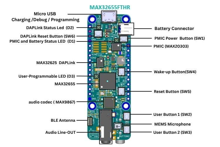
The front side of the board contains most of the active components used during application development. Starting from the top, the Micro-USB connector is used for powering the board, programming the firmware, and serial communication through the onboard DAPLink debugger. Adjacent to it is the Li-Po battery connector, allowing the board to operate from a rechargeable battery for portable applications.
The central portion of the board houses the MAX32655 microcontroller, the MAX32625 DAPLink debugger, and the MAX20303 Power Management IC (PMIC). Around these devices are the status LEDs, user-programmable RGB LED, push buttons, reset and wake-up buttons, and the onboard Bluetooth antenna. At the bottom of the board, you'll find the MAX9867 audio codec, the MEMS microphone, and the 3.5 mm audio line-out connector, providing all the necessary hardware for audio-based BLE applications.
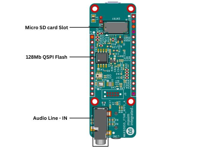
The rear side of the board is dedicated mainly to storage and audio input peripherals. The 128 MB QSPI Flash memory provides high-speed non-volatile storage for firmware and application data, while the microSD card slot enables removable storage for applications such as data logging and audio recording. Also located on this side is the 3.5 mm stereo line-in connector, allowing external audio signals to be captured through the onboard audio subsystem.
Together, the components on both sides of the MAX32655FTHR provide a compact yet feature-rich development platform, with nearly all the essential peripherals integrated directly onto the board. The following sections will take a closer look at each of these components and explain their role in the overall system.
MAX32655FTHR Board Pinout
The following pinout diagrams provide an overview of the MAX32655FTHR development board. They show the GPIO layout, power connections, communication interfaces, and the pin assignments for the onboard peripherals, serving as a quick reference while developing applications.
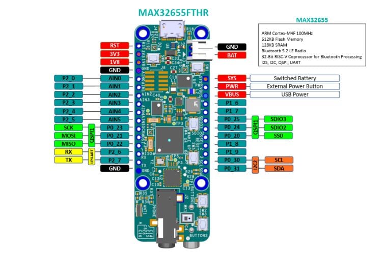
The following figure shows the complete GPIO layout of the MAX32655FTHR development board. In addition to the general-purpose I/O pins, it highlights the available power rails, analog inputs, and communication interfaces, including UART, SPI, I²C, and QSPI. These pins are brought out through the Feather headers, making it easy to interface the board with external peripherals and expansion boards.
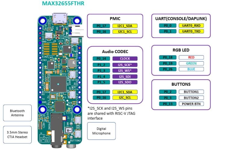
This figure illustrates the GPIO connections for the major onboard peripherals located on the front side of the board. It shows the pin assignments for the PMIC, audio codec, UART console/DAPLink interface, RGB LED, and user buttons, along with the locations of the onboard Bluetooth antenna, digital MEMS microphone, and 3.5 mm headset connector. These mappings are useful when developing applications that make use of the board's integrated peripherals.
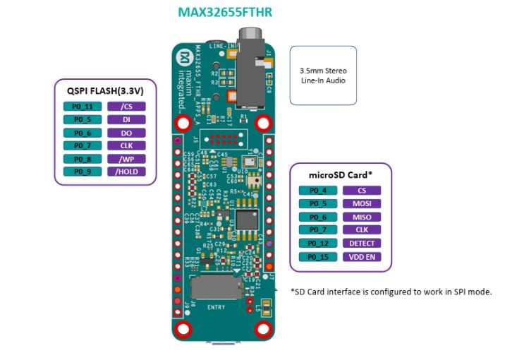
The rear side of the MAX32655FTHR contains the onboard 128 MB QSPI Flash, microSD card slot, and 3.5 mm stereo line-in connector. This figure highlights the GPIO assignments for the QSPI Flash and microSD card interfaces, allowing developers to understand how these onboard storage devices are connected to the MAX32655. Since these peripherals share GPIOs with the Feather headers, referring to these pin assignments helps avoid conflicts when connecting external hardware.
Setting Up the Maxim SDK in VS Code
Step 1⇒ Download the Maxim SDK
Begin by downloading the Maxim Software Development Kit (MSDK), which includes the board support packages, peripheral drivers, example projects, and build tools required for developing on the MAX32655FTHR. Visit the official release page and download the latest installer for your operating system. For Windows, download the MaximMicrosSDK_win.exe
.jpg)
Once downloaded, install the SDK to a convenient location on your system, as this path will be used later during VS Code configuration.
Step 2⇒ Install the Maxim SDK
After downloading the installer, install the Maxim SDK on your system. On Windows, right-click the downloaded installer and select “Run as Administrator”, then proceed through the setup wizard by clicking Next. Choose the installation directory (the default path, C:\MaximSDK, is typically recommended), and ensure that the required components are selected during installation, including Core MSDK, GCC Toolchain, OpenOCD, GNU Make, VS Code Support, etc.
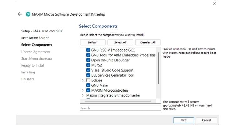
Once configured, click Install and wait for the setup process to complete. This will install the complete development environment needed for building and debugging projects for the MAX32655FTHR Board.
Step 3⇒ Install and Configure Visual Studio Code
Download Visual Studio Code and install it on your system using the standard installation process for your operating system. Once installed, open VS Code and navigate to the Extensions panel from the left sidebar. Search for “C/C++”, select the extension published by Microsoft, and click Install. This extension provides IntelliSense, code navigation, and debugging support required for C/C++ embedded development with the Maxim SDK.
Step 4⇒ Configure VS Code for the Maxim SDK
After installing the required tools, configure Visual Studio Code to recognise the Maxim SDK path. We can open the Command Palette using Ctrl + Shift + P, search for “Preferences: Open User Settings (JSON)”, and open the settings file.
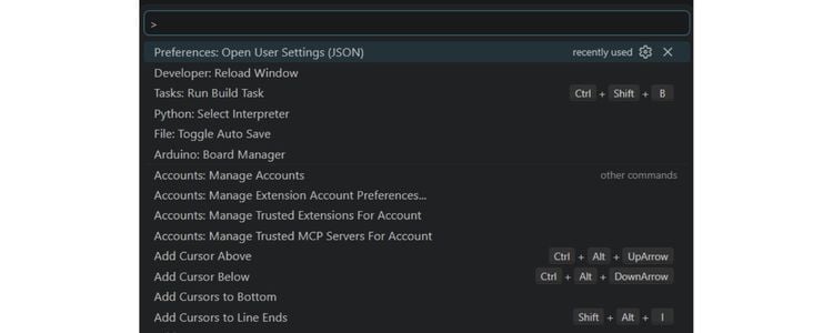
Add the MAXIM_PATH entry pointing to your SDK installation directory (for example, C:/MaximSDK on Windows or ~/MaximSDK on Linux/macOS).
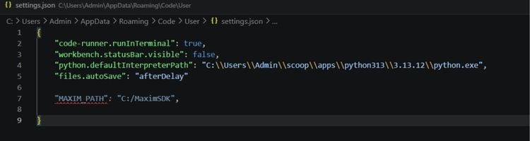
Save the file, then reopen the Command Palette and run Reload Window to restart VS Code and apply the new configuration. Once reloaded, VS Code will be able to detect the Maxim SDK for building and debugging MSDK based projects.
Step 5⇒ Open and Configure Your First Example Project
With the development environment ready, the next step is to open one of the example projects included with the Maxim SDK. The SDK provides several example applications for the MAX32655, covering different peripherals and features. Each example folder also includes a README file that explains its functionality, build instructions, and any additional setup required. For this article, we'll use the BLE_FIT example located under Examples/MAX32655/BLE_FIT. You can choose any other example that suits your application by following the instructions provided in its respective README file. Simply copy the desired example folder to a working location, such as your Desktop or Documents folder, then open it in Visual Studio Code by selecting File → Open Folder.
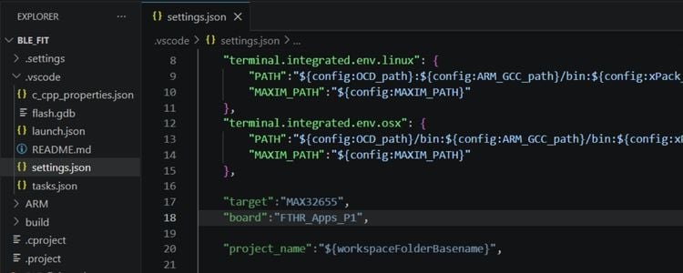
After opening the project, locate the file .vscode/settings.json inside the project directory. This file contains the board and target configuration used by the Maxim build system. Update the "board" field to match your hardware configuration. Set it to "FTHR_Apps_P1". Save the file, then reload VS Code using Ctrl + Shift + P → Reload Window so the updated board configuration is applied. The example project is now configured and ready for building and flashing.
Step 6⇒ Build and Flash the Example Project
This is the final step, where the example project is compiled and flashed onto the board. In Visual Studio Code, press Ctrl + Shift + B and select the Build task to compile the project.
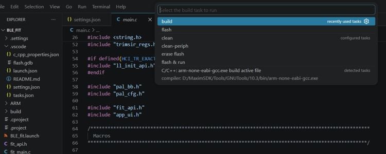
Once the build completes successfully, connect the Board to your computer using a USB cable, and the onboard DAPLink debugger should be detected automatically. Then press Ctrl + Shift + B again, choose the Flash task, and wait for the programming process to finish. During flashing, the DAPLink status LED will blink to indicate that the program has started flashing to the board. After flashing is complete, the firmware will start running on the board.
Developing a BLE-Controlled Audio Player
After exploring the SDK examples, let's build a practical application that showcases several of the MAX32655FTHR's onboard peripherals working together. In this project, we'll develop a Bluetooth Low Energy (BLE) controlled audio player capable of playing MP3 and WAV audio files stored on a microSD card. The player can be controlled either using the onboard push buttons or remotely through a BLE-enabled smartphone application.
This project demonstrates the use of multiple onboard peripherals, including the Bluetooth 5.2 radio for wireless communication, the MAX9867 audio codec for audio playback, the microSD card interface for storing audio files, and the RGB LED for indicating the current playback status. By combining these peripherals into a single application, you'll gain a practical understanding of how to develop feature-rich BLE applications using the MAX32655FTHR.
The same approach can be extended to build a wide range of Bluetooth-enabled embedded applications. By interfacing additional sensors, actuators, or external modules through the available GPIOs and communication interfaces, developers can create applications such as data loggers, wearable devices, environmental monitoring systems, smart controllers, and many other custom BLE projects.
The overall workflow of the application is shown in the following diagram, followed by the working demonstration of the completed project.
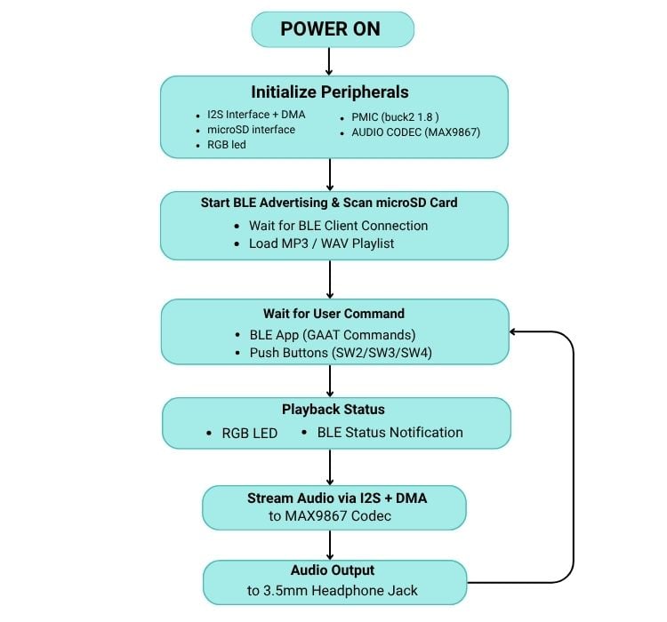
After powering on the board, the firmware initializes the required peripherals, including the PMIC, audio codec, microSD interface, I²S, DMA, and RGB LED. The system then starts BLE advertising while scanning the microSD card for supported audio files. Once initialized, it waits for user commands received either from the onboard push buttons or a connected BLE client. Based on the received command, the selected audio file is streamed through the I²S interface to the onboard audio codec for playback via the 3.5 mm headphone jack, while the RGB LED indicates the current playback status. The system then returns to the command state, allowing continuous user interaction.
The video below shows the complete working of the BLE-controlled audio player, including BLE control, push-button operation, and audio playback from the microSD card.
Overall, the MAX32655FTHR is a compact and feature-rich development board that makes it easy to build Bluetooth® Low Energy applications. In this article, we explored the board's hardware, set up the development environment, and built a BLE-controlled audio player using its onboard peripherals. While this project demonstrates one practical application, the board can be used to develop many other BLE-based prototypes by connecting additional sensors, displays, actuators, or other external modules. Its combination of onboard peripherals, low-power operation, and Feather-compatible design makes it a flexible platform for learning, prototyping, and developing embedded applications.
GitHub Repository
You can find the complete source code and project files on GitHub. The repository also includes a detailed explanation of the project structure, implementation, and the technical concepts used throughout the application.

Add a comment
No account needed. Your comment appears once a moderator has reviewed it.