
Tired of building the same old Arduino projects like blinking LEDs, temperature monitors, and line-following robots? Now it’s time for something fun. It’s time to turn your skills into entertainment by creating your very own Arduino game console project. Instead of just testing circuits, imagine powering up a device you built yourself and jumping straight into a world of retro-style games all packed inside a compact, pocket-sized system.
This Arduino handheld game console is lightweight, easy to carry, and simple to build, making it perfect for hobbyists, electronics engineers, and young tech enthusiasts alike. It’s beginner-friendly, and it is enough to spark creativity and deeper learning.
If you're just getting started or want to strengthen your basics, exploring Arduino projects is a great place to begin. Check out our guide on “Arduino Projects” to build a strong foundation before diving into more advanced creations like this one.
Table of Contents
What Is This Arduino Game Console Project?
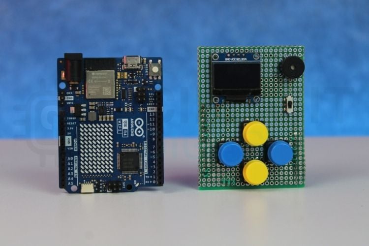
The DIY retro gaming console that I created is based on an Arduino UNO R4 WiFi and is built with components such as a 0.96" SSD1306 OLED display (128×64 px), tactile buttons (4), an active buzzer, a 1S LiPo battery with a 5V boost converter and the custom perfboard of a HAT style. The console has 10 games programmed in Arduino C++ from the ground up, and each game is stored separately in header files; these include Asteroids, Breakout, Dino, Flappy Bird, Maze Runner, Pacman, Pong, Snake, Space Invaders and Tetris.
Console Overview
Games Collection
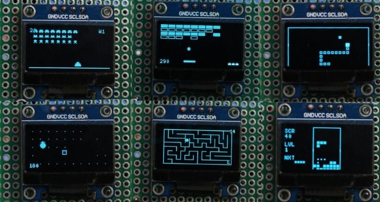
This Arduino game console features a collection of classic arcade-style games, including Asteroids, Breakout, Dino, Flappy Bird, Maze Runner, Pacman, Pong, Snake, Space Invaders, and Tetris, all optimised to run smoothly on the 128x64 OLED display with simple button controls. These are not the exact original versions, but replicas recreated and optimized specifically to suit the hardware limitations of the console.
Compact & Portable Design
This Arduino gaming console is designed to be compact and pocket-sized, making it easy to carry and use anywhere. The hardware is simple and neatly arranged using a custom hat-style board attached to the Arduino R4 WiFi, keeping the overall design clean and organized. The result is a pocket-sized Arduino-based game console you can carry and power anywhere using its onboard LiPo battery.
If you're looking to build something closer to a real commercial-style gaming device, you can check out the article “DIY Handheld Retro Gaming Console Using ESP32” for a more advanced and powerful version of a handheld game console.
Components Required to Build the Arduino Game Console
To turn a regular development board into something truly exciting, we created a custom HAT-style prototype Arduino game console project that mounts directly on top of the Arduino R4 WiFi. This add-on board transforms the Arduino into a compact retro gaming console, keeping everything organized, portable, and easy to assemble. Instead of loose wiring and breadboards, this HAT prototype neatly integrates all the essential components into a clean, ready-to-play setup.
Arduino Game Console Wiring Diagram
The circuit diagram below shows the complete wiring of the Arduino game console. It clearly represents the connections between the OLED display, control buttons, buzzer, battery, and boost converter with the Arduino board. Referring to this diagram while assembling the hardware helps ensure accurate wiring and reliable performance.

Pin Configuration
All the components in the console are connected to specific Arduino pins based on their function. The OLED uses the I2C pins for display communication, the buttons are connected to digital input pins, and the buzzer is attached to a digital output pin. Proper pin mapping ensures the system works smoothly and responds correctly during gameplay. The table below is the definitive reference for wiring this Arduino OLED game console.
| Components | Signal | Arduino Pin | Pin Type |
|---|---|---|---|
| OLED Display (SSD1306 128x64 I2C) | VCC | 5V | Power |
| GND | GND | Ground | |
| SDA | A4 | I2C Data | |
| SCL | A5 | I2C Clock | |
| Button – UP | Signal | D4 | Input |
| Button – DOWN | Signal | D2 | Input |
| Button – LEFT | Signal | D3 | Input |
| Button – RIGHT | Signal | D5 | Input |
| Other side | GND | Ground | |
| Buzzer | + | D7 | Output |
| - | GND | Ground | |
| 5V Boost Converter | OUT + | 5V Pin | Power |
| OUT - | GND | Ground | |
| LiPo Battery | + | Switch to Boost IN + | Power input |
| - | Boost IN - | Ground |
Hardware Assembly
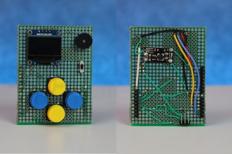
All the components were mounted on a double-sided perf board to keep the setup compact and organized. The entire circuit was designed like a HAT module that sits directly on top of the Arduino R4, making the console neat and portable. The OLED display, push buttons, and buzzer were carefully soldered and connected according to the pin configuration. A 3.7V LiPo battery, along with a 5V boost converter, powers the system, ensuring stable operation in a handheld form factor.
Quick Assembly Tips
∗ Use female header strips on the perf board so the HAT can be removed for reprogramming without desoldering.
∗ Route I2C wires (SDA/SCL) away from button signal wires to minimise noise on the display.
∗ Verify the boost converter output is exactly 5V with a multimeter before connecting to the Arduino's 5V pin.
∗ Use heat-shrink tubing on all LiPo battery leads to prevent short circuits.
∗ Keep connecting wires as short as possible to maintain a compact form factor.
Arduino Game Console Code Overview
The entire code for this Arduino retro game console was written from scratch, with a focus on modularity and easy expansion. Each game is developed individually and stored as a separate header file, keeping the main program clean and well organized. This structure makes it simple to add new games, remove existing ones, or modify and fine-tune gameplay mechanics without affecting the overall system. The modular design ensures flexibility and makes the console easy to customize and upgrade. The complete firmware for this Arduino game console project was written from scratch using a modular architecture.
Step 1 ⇒ Library Includes
#include <Arduino.h>
#include <U8g2lib.h>
#include <Wire.h>
The project begins by including the essential libraries required for the console to function properly.
- The Arduino.h library provides access to core Arduino functions such as pinMode(), digitalRead(), millis(), delay(), and tone(), which are used throughout the program.
- The U8g2lib.h library is responsible for controlling the 128x64 SSD1306 OLED display, allowing graphics, text, menus, and game elements to be rendered smoothly.
- The Wire.h library enables I2C communication between the Arduino and the OLED display, ensuring proper data transfer over the SDA and SCL pins. Together, these libraries form the foundation of the Arduino game console.
Step 2 ⇒ Constants and Pin Definitions
#define SCREEN_W 128
#define SCREEN_H 64
#define BTN_UP 4
#define BTN_DOWN 2
#define BTN_LEFT 3
#define BTN_RIGHT 5
#define BUZZER_PIN 7
This section of the code defines important constants used throughout the program. The screen width and height are set to 128 and 64 respectively, matching the resolution of the SSD1306 OLED display. Defining these values as constants makes it easier to position text and graphics accurately on the screen.
Next, the digital pins connected to the directional buttons are defined. The UP, DOWN, LEFT, and RIGHT buttons are assigned to pins 4, 2, 3, and 5, allowing the program to read user input for menu navigation and gameplay. Finally, the buzzer is assigned to pin 7, which is used to generate sound effects and simple music tones during startup, selection, and game over events.
Step 3 ⇒ Game Header Files
#include "Asteroids.h"
#include "Breakout.h"
#include "Dino.h"
#include "FlappyBird.h"
#include "MazeRunner.h"
#include "Pacman.h"
#include "Pong.h"
#include "Snake.h"
#include "SpaceInvaders.h"
#include "Tetris.h"
This section includes the header files for all the games available in the console. Each game is written in a separate file, such as Asteroids, Breakout, Dino, Flappy Bird, Maze Runner, Pacman, Pong, Snake, Space Invaders, and Tetris. Organizing each game into its own header file keeps the main program clean and modular. This separation of concerns is what makes this how to make a game console with Arduino project easier to manage, debug, and expand in the future, as new games can be added without modifying the core console logic.
Step 4 ⇒ Button Debounce Function
bool btnPressed(uint8_t pin) {
 static uint32_t lastTime[4] = {0, 0, 0, 0};
 static bool lastSt[4] = {true, true, true, true};
 uint8_t idx;
 if (pin == BTN_UP)
   idx = 0;
 else if (pin == BTN_DOWN)
   idx = 1;
 else if (pin == BTN_LEFT)
   idx = 2;
 else if (pin == BTN_RIGHT)
   idx = 3;
 else
   return false;
 bool cur = (digitalRead(pin) == LOW);
 bool edge = cur && !lastSt[idx] && (millis() - lastTime[idx] > 40);
 if (cur != lastSt[idx])
   lastTime[idx] = millis();
 lastSt[idx] = cur;
 return edge;
}
The btnPressed() function is responsible for detecting a clean button press while preventing unwanted multiple triggers caused by mechanical bouncing. It checks the current state of a button and compares it with its previous state to detect a proper press event (edge detection). Static arrays are used to store the last recorded time and previous state of each button, allowing the function to track them individually. A small delay threshold of 40 milliseconds is applied using millis() to debounce the button input. The function returns true only when a valid press is detected, ensuring smooth and reliable menu navigation and gameplay control.
Step 5 ⇒ Setup Function
void setup() {
 pinMode(BTN_UP, INPUT_PULLUP);
 pinMode(BTN_DOWN, INPUT_PULLUP);
 pinMode(BTN_LEFT, INPUT_PULLUP);
 pinMode(BTN_RIGHT, INPUT_PULLUP);
 pinMode(BUZZER_PIN, OUTPUT);
 randomSeed(analogRead(A0));
 u8g2.begin();
 u8g2.setContrast(200);
 u8g2.setFont(u8g2_font_6x10_tr);
 u8g2.setDrawColor(1);
 u8g2.setBitmapMode(0);
 showSplash();
}
The setup() function runs once when the console is powered on and is responsible for initializing the hardware and display settings. All four directional buttons are configured using INPUT_PULLUP, which enables the internal pull-up resistors for stable input reading. The buzzer pin is set as an output so it can generate sound effects. A random seed is initialized using an analog pin reading to ensure unpredictable game behavior where randomness is required. The OLED display is then initialized using u8g2.begin(), followed by setting contrast, font style, draw colour, and bitmap mode for proper rendering. Finally, the showSplash() function is called to display the startup screen before entering the main menu.
Step 6 ⇒ Main Loop
void loop() {
 int sel = menuSelect();
 switch (sel) {
 case 0:
   game_asteroids();
   break;
 case 1:
   game_breakout();
   break;
 case 2:
   game_dino();
   break;
 case 3:
   game_flappy();
   break;
 case 4:
   game_maze();
   break;
 case 5:
   game_pacman();
   break;
 case 6:
   game_pong();
   break;
 case 7:
   game_snake();
   break;
 case 8:
   game_spaceinvaders();
   break;
 case 9:
   game_tetris();
   break;
 }
}
The loop() function acts as the main control centre of the console. It first calls the menuSelect() function, which displays the game selection menu and returns the number corresponding to the chosen game. Based on this selected value, a switch statement is used to launch the respective game function, such as game_snake(), game_pong(), or game_tetris(). Each case represents one of the ten available games. Once a game finishes, the program naturally returns to the loop, bringing the user back to the menu to select another game. This structure ensures smooth navigation and continuous gameplay without restarting the console.
Working Video
Below, you can see the working video of the game console in action.
When the console is powered on, the display first shows the main game console screen, prompting the user to press any button to continue. Once a button is pressed, the game's list menu appears. The UP and DOWN buttons are used to scroll through the list of available games, and a game can be selected by pressing either the LEFT or RIGHT button. The video below shows the complete Arduino handheld game console in action, from startup splash screen through game selection to live gameplay across several titles.
After selecting a game, it loads immediately, and gameplay begins. Once the game is over, the console automatically returns to the games list page, allowing another game to be selected.
Future Updates
- Expand the console by adding more games and new gameplay features.
- Improve the user experience with high score saving, additional sound effects, and a more interactive menu design.
- Introduce adjustable difficulty levels to give players different challenge options.
- Enable wireless multiplayer support using the Arduino UNO R4 WiFi for connected gameplay between two consoles.
- Enhance hardware performance through power optimization for longer battery life and support for a larger display.
Challenges Faced During Development
Library Compatibility Issue with the Arduino UNO R4
Another issue faced during development was related to the OLED graphics library. The commonly used Adafruit GFX library was not fully compatible with the Arduino UNO R4 in this setup, which caused display initialisation and rendering problems. To resolve this, the U8g2 library was used instead.
The U8g2 library provides better compatibility with the UNO R4 and offers efficient full-frame buffering, smoother text rendering, and flexible font support. Switching to U8g2 ensured stable OLED performance and improved overall display handling in the console. Not every Arduino board is suited for driving an OLED display and running game logic simultaneously. Read our
Arduino board comparison guide to understand why processing speed and RAM matter when choosing hardware for display-heavy projects.
Button Bouncing and Debouncing
Another common issue in hardware projects is button bouncing. When a mechanical push button is pressed, it doesn’t switch cleanly from OFF to ON. Instead, it rapidly fluctuates between HIGH and LOW for a few milliseconds, which can cause multiple unintended inputs in the game, such as skipping menu options or triggering repeated actions.
To solve this, a software debouncing technique was implemented in the btnPressed() function. By using timing checks with millis() and detecting edge transitions, the program ensures that only a clean and intentional button press is registered. This results in smoother menu navigation and more accurate gameplay control. Looking for more build ideas beyond gaming? Our curated list of electronics projects covers everything from home automation to robotics, giving you a clear next step once this console is complete.
Frequently Asked Questions About Arduino Game Console
⇥ Can more games be added to the console?
Yes. Since each game is written in a separate header file, new games can be added easily by creating a new game file and including it in the main menu system.
⇥ Why is a 5V boost converter used?
The console is powered using a 3.7V LiPo battery, but the Arduino requires 5V for stable operation. The boost converter steps up the battery voltage to a consistent 5V output.
⇥ Are these original arcade games?
No. These are lightweight replicas inspired by classic arcade titles. They are recreated and optimized to run within the memory and performance limits of the Arduino platform.
⇥ Can this project be upgraded to a more powerful console?
Yes. For improved performance and graphics, the design can be upgraded to an ESP32-based handheld gaming console with larger displays, SD card support, and additional features.
⇥ How is button debouncing handled in the code?
Software debouncing is used in btnPressed() to check for a LOW-to-HIGH edge transition and only accept the button press as valid if it has been at least 40 milliseconds since the last edge transition occurred in the button's state. By filtering out the mechanical contact bounce using a timer, each of the four buttons has its own static array to store the last state and last-change timestamp, allowing independent polling and no false triggering of buttons.
Arduino Game Console GitHub Repository
Find the project images and code for the handheld Arduino game console in the GitHub repository. It includes the source code, circuit schematics, and additional documentation to help you build and modify your own handheld console.


Gaming Console Projects
Build your own gaming consoles with step-by-step tutorials and project guides. Great for makers and electronics enthusiasts interested in DIY gaming hardware.

DIY Handheld Game Console using Arduino Pro Micro and Arduboy
A DIY handheld gaming console built using an Arduino Pro Micro and Arduboy platform, featuring an OLED display, buttons, and battery power to play simple retro-style games.

DIY Raspberry Pi Gaming Console using RetroPie
Turn your Raspberry Pi into a retro gaming console with RetroPie. This guide shows how to install RetroPie and start playing classic games.

DIY Raspberry Pi Portable Games Console
Build your own Raspberry Pi portable game console and enjoy classic retro games on a handheld DIY gaming device.
Complete Project Code
/*
============================================================
               ARDUINO GAMING CONSOLE
============================================================
  Hardware:
    - Arduino UNO R4 (Minima or WiFi)
    - 128x64 I2C OLED (SSD1306)   SDA=A4, SCL=A5
    - Buzzer                       Pin 7
    - BTN_UP                       Pin 4
    - BTN_DOWN                     Pin 2
    - BTN_LEFT                     Pin 3
    - BTN_RIGHT (Flap / Select)    Pin 5
============================================================
*/
#include <Arduino.h>
#include <U8g2lib.h>
#include <Wire.h>
// ── Display ────────────────────────────────────────────────
U8G2_SSD1306_128X64_NONAME_F_HW_I2C u8g2(U8G2_R0, /* reset=*/U8X8_PIN_NONE);
#define SCREEN_W 128
#define SCREEN_H 64
// ── Buttons ────────────────────────────────────────────────
#define BTN_UP 4
#define BTN_DOWN 2
#define BTN_LEFT 3
#define BTN_RIGHT 5
// ── Buzzer ─────────────────────────────────────────────────
#define BUZZER_PIN 7
// ═══════════════════════════════════════════════════════════
//  UTILITY HELPERS
// ═══════════════════════════════════════════════════════════
bool btnPressed(uint8_t pin) {
 static uint32_t lastTime[4] = {0, 0, 0, 0};
 static bool lastSt[4] = {true, true, true, true};
 uint8_t idx;
 if (pin == BTN_UP)
   idx = 0;
 else if (pin == BTN_DOWN)
   idx = 1;
 else if (pin == BTN_LEFT)
   idx = 2;
 else if (pin == BTN_RIGHT)
   idx = 3;
 else
   return false;
 bool cur = (digitalRead(pin) == LOW);
 bool edge = cur && !lastSt[idx] && (millis() - lastTime[idx] > 40);
 if (cur != lastSt[idx])
   lastTime[idx] = millis();
 lastSt[idx] = cur;
 return edge;
}
bool btnHeld(uint8_t pin) { return digitalRead(pin) == LOW; }
void beep(uint16_t freq, uint16_t ms) { tone(BUZZER_PIN, freq, ms); }
void waitRelease() {
 delay(30);
 while (btnHeld(BTN_UP) || btnHeld(BTN_DOWN) || btnHeld(BTN_LEFT) ||
        btnHeld(BTN_RIGHT))
   delay(10);
}
void centreStr(const char *s, uint8_t y) {
 uint8_t w = u8g2.getStrWidth(s);
 u8g2.drawStr((SCREEN_W - w) / 2, y, s);
}
// ── Music Helpers ──
void playStartMusic() {
 // ~2.5 second Upbeat Jingle
 beep(523, 150);
 delay(200); // C5
 beep(659, 150);
 delay(200); // E5
 beep(784, 150);
 delay(200); // G5
 beep(523, 150);
 delay(200); // C5
 beep(784, 150);
 delay(200); // G5
 beep(1046, 300);
 delay(400); // C6
 beep(880, 150);
 delay(200);      // A5
 beep(1046, 500); // C6
}
void playGameOverMusic() {
 // ~2.5 second Descending Theme
 beep(392, 250);
 delay(300); // G4
 beep(349, 250);
 delay(300); // F4
 beep(329, 250);
 delay(300); // E4
 beep(261, 500);
 delay(600);     // C4
 beep(196, 700); // G3
}
// ═══════════════════════════════════════════════════════════
//  GAME HEADERS
// ═══════════════════════════════════════════════════════════
#include "Asteroids.h"
#include "Breakout.h"
#include "Dino.h"
#include "FlappyBird.h"
#include "MazeRunner.h"
#include "Pacman.h"
#include "Pong.h"
#include "Snake.h"
#include "SpaceInvaders.h"
#include "Tetris.h"
// ═══════════════════════════════════════════════════════════
//  SPLASH + MENU
// ═══════════════════════════════════════════════════════════
void showSplash() {
 u8g2.clearBuffer();
 u8g2.setFont(u8g2_font_ncenB10_tr);
 centreStr("GAME CONSOLE", 28);
 u8g2.setFont(u8g2_font_6x10_tr);
 centreStr("Press any button...", 48);
 u8g2.sendBuffer();
 playStartMusic();
 while (!btnHeld(BTN_UP) && !btnHeld(BTN_DOWN) && !btnHeld(BTN_LEFT) &&
        !btnHeld(BTN_RIGHT))
   delay(15);
 waitRelease();
}
void gameOver(uint16_t score) {
 char buf[20];
 snprintf(buf, sizeof(buf), "Score: %u", score);
 u8g2.clearBuffer();
 u8g2.setFont(u8g2_font_ncenB10_tr);
 centreStr("GAME OVER", 28);
 u8g2.setFont(u8g2_font_6x10_tr);
 centreStr(buf, 44);
 centreStr("Press any button", 58);
 u8g2.sendBuffer();
 playGameOverMusic();
 delay(400);
 waitRelease();
 while (!btnHeld(BTN_UP) && !btnHeld(BTN_DOWN) && !btnHeld(BTN_LEFT) &&
        !btnHeld(BTN_RIGHT))
   delay(15);
 waitRelease();
}
#define GAME_COUNT 10
int menuSelect() {
 const char *names[GAME_COUNT] = {
     "1. Asteroids",      "2. Breakout", "3. Dino Run", "4. Flappy Bird",
     "5. Maze Runner",    "6. Pacman",   "7. Pong",     "8. Snake",
     "9. Space Invaders", "10. Tetris"};
 int sel = 0;
 int top = 0;
 const int VISIBLE = 4;
 while (true) {
   if (sel < top)
     top = sel;
   if (sel >= top + VISIBLE)
     top = sel - VISIBLE + 1;
   u8g2.clearBuffer();
   u8g2.setFont(u8g2_font_6x10_tr);
   u8g2.drawBox(0, 0, SCREEN_W, 11);
   u8g2.setDrawColor(0);
   centreStr("** GAME CONSOLE **", 9);
   u8g2.setDrawColor(1);
   for (int i = 0; i < VISIBLE; i++) {
     int idx = top + i;
     if (idx >= GAME_COUNT)
       break;
     int y = 13 + i * 13;
     if (idx == sel) {
       u8g2.drawRBox(0, y, SCREEN_W - 10, 12, 2);
       u8g2.setDrawColor(0);
       u8g2.drawStr(4, y + 9, names[idx]);
       u8g2.setDrawColor(1);
     } else {
       u8g2.drawStr(4, y + 9, names[idx]);
     }
   }
   u8g2.drawFrame(SCREEN_W - 7, 12, 6, 52);
   int thumbH = max(6, 52 / GAME_COUNT * VISIBLE);
   int thumbY = 12 + (sel * (52 - thumbH)) / (GAME_COUNT - 1);
   u8g2.drawBox(SCREEN_W - 6, thumbY, 4, thumbH);
   if (top > 0)
     u8g2.drawStr(SCREEN_W - 8, 13, "^");
   if (top + VISIBLE < GAME_COUNT)
     u8g2.drawStr(SCREEN_W - 8, 62, "v");
   u8g2.sendBuffer();
   delay(100);
   if (btnPressed(BTN_UP)) {
     sel = (sel + GAME_COUNT - 1) % GAME_COUNT;
     beep(800, 25);
   }
   if (btnPressed(BTN_DOWN)) {
     sel = (sel + 1) % GAME_COUNT;
     beep(800, 25);
   }
   if (btnPressed(BTN_LEFT) || btnPressed(BTN_RIGHT)) {
     beep(1200, 60);
     waitRelease();
     return sel;
   }
 }
}
void setup() {
 pinMode(BTN_UP, INPUT_PULLUP);
 pinMode(BTN_DOWN, INPUT_PULLUP);
 pinMode(BTN_LEFT, INPUT_PULLUP);
 pinMode(BTN_RIGHT, INPUT_PULLUP);
 pinMode(BUZZER_PIN, OUTPUT);
 randomSeed(analogRead(A0));
 u8g2.begin();
 u8g2.setContrast(200);
 u8g2.setFont(u8g2_font_6x10_tr);
 u8g2.setDrawColor(1);
 u8g2.setBitmapMode(0);
 showSplash();
}
void loop() {
 int sel = menuSelect();
 switch (sel) {
 case 0:
   game_asteroids();
   break;
 case 1:
   game_breakout();
   break;
 case 2:
   game_dino();
   break;
 case 3:
   game_flappy();
   break;
 case 4:
   game_maze();
   break;
 case 5:
   game_pacman();
   break;
 case 6:
   game_pong();
   break;
 case 7:
   game_snake();
   break;
 case 8:
   game_spaceinvaders();
   break;
 case 9:
   game_tetris();
   break;
 }
}
Comments
All the components used here are generic. The switches used are 12x12x7.3mm switches that are compatible with Omron B3F-4055, along with the switch caps.
.jpg) I redid this with a 1.3" SH1106 oled. Easier on my 82 yr old eyes. :-)
I redid this with a 1.3" SH1106 oled. Easier on my 82 yr old eyes. :-)
Question: How would we make it so when we push a button after "Game over" we would stay in the same game to try again?

Very nice, but How about providing part numbers for components like the switches.