

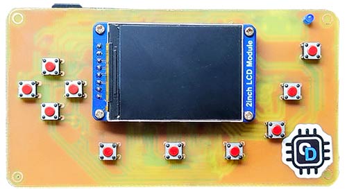
Do you remember the old classic 8-bit games? Perhaps you enjoyed your leisure time in front of an early home computer or video game system. They were so nostalgic, and every kid in that era loved them. Now they are replaced with modern high-end graphics and game dynamics. Yet many people still love to play those classic games. Nowadays, the only way to play these games is through emulators. In this tutorial, we will explore how to create a device that can emulate classic games. This ESP32 game console is based on the popular Odroid Go, with updated firmware and a new IPS display. And the firmware used is a modified version of ducalex's retro-go firmware. Also, you can explore more game builds on our website, like this LED Therapy Game, a gaming console using Arduino and an OLED display, or this LED Arcade Game, which uses Arduino Nano.
Retro Game Console using ESP32 - Quick Overview
Build Time: 8-12 hours | Cost: $50-80 | Difficulty: Intermediate-Advanced
What You'll Learn: ESP32 programming, SPI communication, PCB design, Firmware modification
Applications: Retro gaming, Portable entertainment, Emulator development, DIY electronics
Table of Contents
Required Components
Building an ESP32 handheld game console requires carefully selected components. We designed this circuit with generic components or modules, making the replication process easy.
ESP32 Wrover Kit with 16MB flash – 1
Waveshare 2” 320x240 IPS display module with ST7789V driver – 1
TP4056 module with protection – 1
AO3401 SMD P-Channel MOSFET – 1
SD Card Slot – 1
SMD Slide switch 1P2T – 1
3.5mm Audio Jack SMD PJ-327-A -1
3.7V Lipo battery – 1
2Pin JST XH battery connector – 1
6x6x6xmm tactile switches – 10
3mm LED – 1
3.3v Active buzzer – 1
100k Resistor – 2
10k Resistor – 7
1k Resistor – 1
0.01uf Capacitor – 3
Circuit Design
The complete circuit diagram of this ESP32 game console is displayed below.

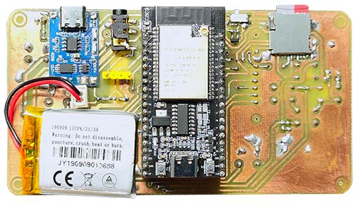
The circuit is built around readily available off-the-shelf components. Connections are straightforward and easy to understand. The input supply is connected to the TP4056 module with a built-in protection circuit. If your battery already has a protection circuit built in, you can simply use the TP4056 module without the protection circuit. The battery is connected to the output of the TP4056 module. From there, the supply is connected to a high-side P-Channel MOSFET. By default, the gate of this MOSFET is pulled up to the VBAT level. When the small slide switch is switched on, the gate will be connected to the ground, and the MOSFET will be turned on. This simple circuitry will allow us to turn on and off the entire device using a tiny slide switch.
Component Connections Detail
The power from the MOSFET is distributed to other components. The display is connected to the ESP32 Wrover kit using the SPI pins. The backlight brightness is controlled using the PWM from GPIO14. The SD card is also connected using the same SPI line. The sound is taken out from the GPIO26 and connected to a 3.5mm audio jack. You can either use the audio jack to connect a headphone, or you can use a buzzer with the audio jack switch terminal. An LED is connected to the GPIO2 to show the disk read status. Whenever the system is busy reading from the SD card, the LED will light up. All the switches are connected to various GPIO pins, and the state of these pins is monitored to detect a key press.
PCB Design
To make this DIY retro game console project easier, we designed a PCB for the project. The image below shows the dimensions of the PCB. It's a homemade etched PCB, and its necessary files can be downloaded from the GitHub link given at the end of this article. Here's how you make PCBs at home.
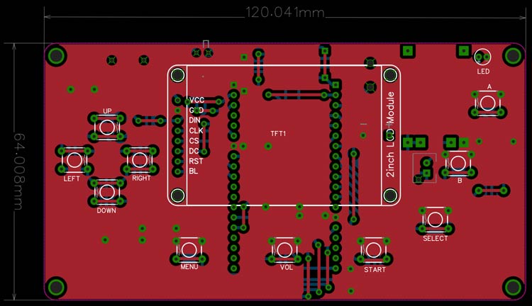
The image below shows the 2D representation of the PCB.
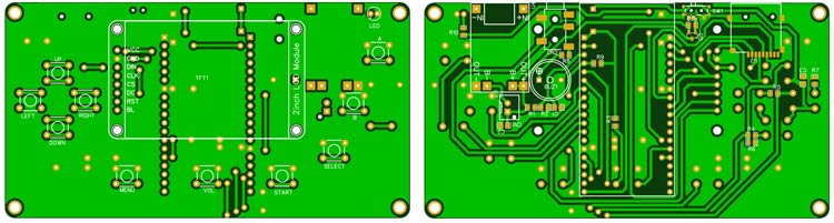
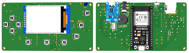
And the below image shows the 3D illustration of the same PCB. In the 3D model, you can see the placement of all the components.
Modified Firmware for ESP32 Retro Gaming
As mentioned earlier, the firmware used is a modified version of ducalex's retro-go firmware. The original firmware is coded to use with the ILI9341 display. Since we are using an IPS display with an ST7789V driver, we can’t use the original firmware. Thankfully, most of the display functions are somewhat similar for both the LCD driver chips. But we must change the display initialisation codes and the gamma settings. You can find the modified firmware source code in the following GitHub repo: Retro-go-ST7789. To use the firmware, you can either use the prebuilt image or you can build it yourself. The prebuilt image file can be found at the Circuit Digest GitHub repo linked at the end of this tutorial.
Supported Gaming Systems
Nintendo: NES, SNES (slow), Gameboy, Gameboy Color, Game & Watch
Sega: SG-1000, Master System, Mega Drive / Genesis, Game Gear
Coleco: Colecovision
NEC: PC Engine
Atari: Lynx
Others: DOOM (including mods!)
Firmware features:
This gaming console built using ESP32 includes professional features such as:
In-game menu
Favorites and recently played
GB color palettes, RTC adjust and save
NES color palettes, PAL roms, NSF support
More emulators and applications
Scaling and filtering options
Better performance and compatibility
Turbo Speed/Fast forward
Customizable launcher
Cover art and save state previews
Multiple save slots per game
Wifi file manager
And more!
Building the Firmware from Source
Development Environment Setup
The firmware is written for the ESP32 IDF. The currently supported versions are 4.1 to 4.4, and the recommended version is 4.3.. With any other updated version of ESP32 IDF, the build may fail. Follow the following link to install and configure ESP32 IDF version 4.3.
Required Patches
Once installed and configured, apply the following patches to the IDF. Patches are located in tools/patches and can be applied to your global ESP-IDF installation; they will not break your other projects/devices.
Essential Patches:
sdcard-fix: This patch is mandatory for the ODROID-GO (and clones).
panic-hook: This is to help users report bugs. See captured crash logs below for more details. The patch is optional but recommended.
enable-exfat: Enable exFAT support. I don't recommend it, but it works if you need it.
To apply the patches, you need open a terminal in your ESP-IDF installation ($IDF_PATH) and run the command as per the template below. You should do the same for all the necessary patches.
Patch Application Command:
patch -p1 < "/path/to/retro-go/tools/patches/ sdcard-fix (esp-idf 4.2 and 4.3).diff "
Build Process
Once the patches are applied run the following command from the root folder to build the firmware image.
./rg_tool.py release
Flashing the Firmware
To flash the firmware, you can either one of the following methods.
Method 1: Using ESPtool (Recommended)
To use the ESPtool, make sure you have installed the ESP IDF. You can find the instructions for that in the previous section. Once installed and configured, open the terminal in the same folder as the firmware image and use the following command to flash the firmware.
esptool.py write_flash --flash_size detect 0x0 retro-go_*.img
Method 2: ESP32 Flash Download Tool
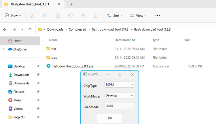
First, download the ESP32 Flash Download Tool
Extract it to a folder and double-click on the exe file to run it. When prompted, select ESP32 in the chip type field and click on OK
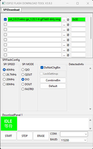
Select the firmware file with the img extension and add the address as 0x00. Select the proper COM port and click on erase. Once the flash erase is complete, click on START to flash the firmware
That's it. You are ready to use the console. Insert the SD card and enjoy the gameplay.
Using Your ESP32 Game Console
SD Card Setup
To use the console, format the SD card to FAT32 format. Copy the folders named roms and romart to the SD card. Keep in mind that the ROM folder doesn’t contain any game ROMs. You must download the games you need from other sources and place them in the corresponding ROM folder within the roms folder(eg, Nintendo ROMs in the NES folder).
Cover Art Configuration
You can add missing cover art by creating a PNG image (160x168, 8-bit) named according to the following scheme: /romart/nes/A/ABCDE123.png, where nes is the same as the rom folder, and ABCDE123 is the CRC32 of the game (press A -> Properties in the launcher to find it).
Wi-Fi Configuration
To use Wi-Fi, you will need to add your config to /retro-go/config/wifi.json file. It should look like this:
{
  "ssid": "my-network",
  "password": "my-password"
}
File Manager Access
To use the file manager, find the IP of your device in the about menu. Then on your PC navigate to http://192.168.x.x/ to access the file manager.
The video below shows the OdroidGo based gameplay on the device we just made.
GitHub Repository
You can download all the necessary files from the Circuit Digest GitHub repo, from the following link


Frequently Asked Questions (FAQ)
Q1. Will any ESP32 board do for this project?
Not really. You’ll need an ESP32 with 16MB flash; otherwise, some emulators and larger games won’t run. The ESP32 Wrover Kit is the safest bet because the firmware is already tuned for it.
Q2. Do I have to recompile the firmware myself?
No. If you just want to play, grab the prebuilt image and flash it with esptool.py or the ESP32 Flash Download Tool. Recompiling is only needed if you want to tweak features or support a different display.
Q3. What format should my SD card be in?
Stick with FAT32. It’s the most stable with this firmware. exFAT can be enabled with patches, but FAT32 is what I recommend for fewer headaches.
Q4. Are the game ROMs included in the repo?
Nope, and they really can’t be for copyright reasons. You’ll have to provide your own ROMs and drop them into the right folders inside /roms (e.g., NES games in /roms/nes).
Q5. Does SNES emulation run at full speed?
Not always. NES, Game Boy, and Master System titles are smooth. SNES works, but some games will feel slow because the ESP32 just doesn’t have the horsepower of dedicated SNES hardware.
Related ESP32 Projects
Create new skills and inspiration by exploring other hands-on builds with the ESP32. From experimenting with OLED text displays to turning your board into an oscilloscope or even a smartwatch.

ESP32 with OLED Display Module
In this article, we will discuss how the OLED Display module works, how to interface it with ESP32, and we will also learn to display text and characters on the OLED Display module.

DIY ESP32 oscilloscope with TFT display. Build, program, and test signals with real-time waveform visualization for your electronics projects.

In this article we discussed the functional block diagram of the ESP32-based DIY Smartwatch and also we created the smartwatch faces
Comments
is 16MB version really required?.... as I can see the compiled .img firmware is 1.43MB and can be easily flashed on a 4MB module/devkit
You can use a 4MB version. I just used the one that was available with me.
Thank you very much for the amazing project.
I'm going to make this and can you please provide pdf version of the pcb..?

I built this, flashed the img from repo and... black screen :D Display backlight is turned on but doesnt show anything.