

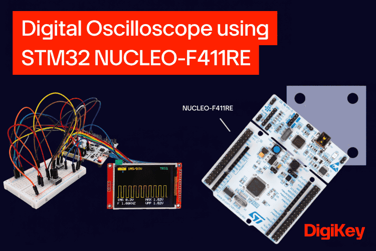
An oscilloscope is the one instrument every electronics engineer reaches for when a circuit misbehaves. A multimeter tells you a single number, but an oscilloscope shows how a voltage changes over time: the shape of a PWM signal, the bounce of a switch, or the ripple on a sensor output. Bench oscilloscopes are expensive, though, and the best way to understand how one works is to build it yourself.
In this project, we build a single-channel digital oscilloscope using the STM32F411RE microcontroller on a NUCLEO-F411RE board. The input signal is buffered by an MCP6002 op-amp, sampled by the STM32's 12-bit ADC at up to 600,000 samples per second using a timer and DMA, and drawn on a 2.8-inch ILI9341 SPI TFT display. A rotary encoder and two push buttons give it real front-panel controls: TIME/DIV, VOLTS/DIV, position, trigger level and edge, RUN/STOP and SINGLE capture. The scope also measures maximum voltage, peak-to-peak voltage and frequency automatically, and generates its own square-wave test signal so you always have something to measure.
Specification | Value |
| Channels | 1 |
| Input range | 0–3.3 V (DC coupled) |
| Sample rate | 1.5 kS/s to 600 kS/s |
| Time base | 50 µs/div to 20 ms/div |
| Vertical scale | 0.1, 0.2, 0.5, 1 V/div |
| Useful bandwidth | about 50 kHz |
| Resolution | 12-bit |
| Measurements | MAX, Vpp, frequency |
System Architecture and Components
The oscilloscope is built from three blocks: an analog front end that conditions the signal, the STM32 that captures and analyses it, and a display with controls for the user.
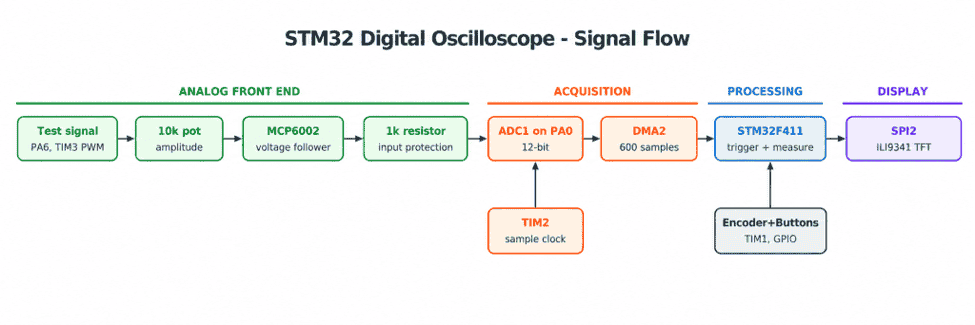
This is the input stage; the signal first passes through an MCP6002 op-amp wired as a unity-gain voltage follower. The follower has a very high input impedance, so it does not load the circuit being measured, and a low output impedance that charges the ADC's sampling capacitor quickly. A 1 kΩ series resistor protects the STM32 pin. For testing, the STM32 generates its own 0–3.3 V square wave on PA6, and a 10 kΩ potentiometer sets its amplitude.
Then in the Processing stage, the STM32F411RE runs at 84 MHz. Timer TIM2 triggers the ADC at an exact rate (30 samples per screen division), and DMA stores 600 samples in RAM without CPU involvement. The firmware then finds the trigger point, calculates min, max, peak-to-peak and frequency, and renders the frame.
Next, the output controls the 320 × 240 ILI9341 display is driven over SPI2 at 21 MHz. A rotary encoder, decoded in hardware by TIM1, selects and changes settings, while two push buttons provide RUN/STOP and SINGLE capture.
Components Required
All the components for this project were ordered from DigiKey.
- NUCLEO-F411RE – STM32F411RE Nucleo-64 development board with built-in ST-LINK (1)
- MCP6002-I/P – dual rail-to-rail op-amp, 1 MHz, 8-pin DIP (1)
- 2.8-inch 240 × 320 SPI TFT display with ILI9341 controller (1)
- Rotary encoder module with push switch, 5 pins: CLK, DT, SW, +, GND (1)
- 6 mm tactile push buttons (2)
- 10 kΩ potentiometer (1)
- 1 kΩ resistor (1)
- 100 nF ceramic capacitor (1)
- LDR light sensor module with VCC, GND, AO pins (1, optional for the sensor demo)
- Breadboard and jumper wires
- USB cable for the Nucleo board
Software: STM32CubeIDE and STM32CubeMX (free from STMicroelectronics), with the STM32Cube FW_F4 HAL library.
Pin Connections
The project uses 13 STM32 pins, all reachable from the Nucleo's Arduino and Morpho headers.
| Function | STM32 pin | Nucleo header | Connected to |
| ADC input (ADC1_IN0) | PA0 | A0 (CN8 pin 1) | MCP6002 output via 1 kΩ |
| Test signal (TIM3_CH1 PWM) | PA6 | D12 (CN5 pin 5) | Potentiometer end A |
| TFT CS | PB12 | CN10 pin 16 | TFT CS |
| TFT RESET | PB2 | CN10 pin 22 | TFT RESET |
| TFT DC | PB1 | CN10 pin 24 | TFT DC |
| SPI2 MOSI | PB15 | CN10 pin 26 | TFT SDI (MOSI) |
| SPI2 SCK | PB13 | CN10 pin 30 | TFT SCK |
| SPI2 MISO | PB14 | CN10 pin 28 | TFT SDO (MISO) |
| Encoder CLK (TIM1_CH1) | PA8 | D7 (CN9 pin 8) | Encoder CLK |
| Encoder DT (TIM1_CH2) | PA9 | D8 (CN5 pin 1) | Encoder DT |
| Encoder switch | PB10 | D6 (CN9 pin 7) | Encoder SW |
| RUN/STOP button | PB4 | D5 (CN9 pin 6) | Button to GND |
| SINGLE button | PB5 | D4 (CN9 pin 5) | Button to GND |
| USER button (on board) | PC13 | – | Test signal frequency |
| LED LD2 (on board) | PA5 | – | Frame heartbeat |
Power: the TFT (VCC and LED), the MCP6002 (pin 8) and the encoder module (+) all run from the Nucleo's 3V3 pin, and every ground is common. SPI2 is used instead of SPI1 because SPI1's clock pin, PA5, also drives the on-board LED.
Circuit Diagram
The complete circuit of the STM32 oscilloscope is shown below; it fits on a single breadboard next to the Nucleo board.

Actual Circuit on Breadboard
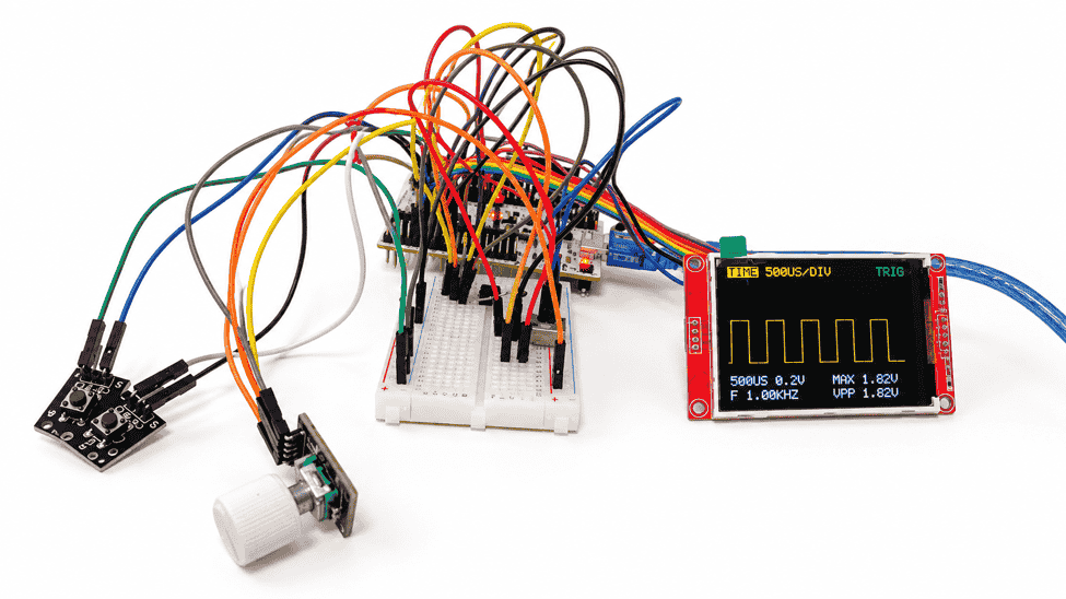
In the analog front end, the STM32 outputs a 0–3.3 V square wave on D12 (PA6). It goes to one end of the 10 kΩ potentiometer, whose other end is grounded, so the wiper delivers a square wave of adjustable amplitude. The wiper feeds pin 3 (non-inverting input) of the MCP6002. Pins 1 and 2 are tied together, which makes op-amp A a unity-gain voltage follower. Its output reaches the ADC pin PA0 through a 1 kΩ resistor that limits current if anything goes wrong. A 100 nF capacitor across pins 8 and 4 decouples the op-amp supply. The unused op-amp B is parked safely: pin 5 to GND and pin 6 tied to pin.
In the display, the ILI9341 TFT connects to SPI2 (SCK PB13, MOSI PB15, MISO PB14) with three control lines: CS on PB12, DC on PB1 and RESET on PB2. The touch and SD card pins of the module are not used.
In the controls, the encoder's CLK and DT go to PA8 and PA9, which are the TIM1 channel 1 and 2 inputs, so the timer can decode the knob in hardware. The encoder's push switch and the two buttons connect their pins to GND when pressed; the firmware enables the STM32's internal pull-up resistors, so no external resistors are needed. The encoder module must be powered from 3V3 so its CLK/DT pull-ups stay at a safe 3.3 V.
The MCP6002 is a rail-to-rail op-amp, so it works from the same single 3.3 V supply as the STM32 and can swing almost to 0 V and 3.3 V. Its datasheet limits the inputs to 1 V beyond the supply rails, so only 0–3.3 V signals should be connected to this front end.
Initial Testing and Development Approach
The oscilloscope was built in small, testable stages, so each subsystem was proven before the next one was added on top.
Display first, A small ILI9341 driver was written from scratch (reset, sleep-out, pixel format, orientation, address window, pixel write) so every step of talking to the display is visible rather than hidden in a library. The first goal was simply to fill the screen and print text.
ADC with a known DC voltage, The potentiometer was connected between 3.3 V and GND, buffered by the MCP6002 and read on PA0. Turning the knob from end to end gave readings from about 3 to 4089 counts, and the top end displayed about 3295 mV, which confirmed the whole analog path.
Live waveform, Samples were mapped to screen coordinates and drawn over a grid.
Accurate time base and trigger, The free-running ADC was replaced by a timer-triggered ADC, and a software trigger was added so the waveform stands still.
Test signal and controls, A PWM test signal, the rotary encoder and the RUN/STOP and SINGLE buttons were added last.
Display Test Code
This is the first sketch used to bring up the display over SPI2. If this works, the wiring, SPI settings and driver are all correct.
#include "main.h"
#include "ili9341.h"
int main(void)
{
  HAL_Init();
  SystemClock_Config();
  MX_GPIO_Init();
  MX_SPI2_Init();
  ILI9341_Init();                 // hardware + software reset, sleep out, RGB565
  ILI9341_SetRotation(1);         // landscape, 320 x 240
  ILI9341_FillScreen(ILI9341_BLACK);
  ILI9341_DrawStringSize(60, 100, "HELLO STM32", ILI9341_YELLOW, ILI9341_BLACK, 2);
  ILI9341_DrawGraphGrid(10, 28, 300, 160, ILI9341_GRAY);
  while (1)
  {
  }
}
Early tests exposed several problems, and fixing them shaped the final design:
Problem seen | Cause | Solution |
| Full-screen refresh was very slow | Pixels were sent 2 bytes per SPI call | Build whole rows in RAM and send each row in one SPI transfer |
| Old waveforms piled up | Nothing erased the previous trace | Repaint the whole graph area every frame |
| Grid blinked and got erased by the trace | Grid and trace drawn separately | Draw grid, trace and markers together, row by row |
| TIME/DIV label was wrong | ADC was free-running at about 219 kS/s | Let TIM2 trigger each ADC conversion at an exact rate |
| Waveform jumped around | No trigger, and DMA overwrote data while drawing | One-shot DMA snapshot of 600 samples plus an edge trigger |
Code Explanation
The firmware is one loop that captures, analyses and draws a frame, while three hardware timers and the DMA do all the time-critical work. The complete code is at the end of this article; the key parts are explained here.
Peripheral | Job |
| TIM2 | Sample clock: each overflow triggers one ADC conversion |
| ADC1 + DMA2 Stream 0 | Converts PA0 and stores 600 samples in RAM |
| TIM3 CH1 | 50 % duty-cycle test signal on PA6 |
| TIM1 (encoder mode) | Counts rotary encoder clicks in hardware |
| SPI2 | Sends pixels to the ILI9341 at 21 MHz |
Timer-Triggered ADC Sampling with DMA
For a correct time axis, samples must be taken at an exact rate. TIM2 runs from the 84 MHz timer clock, and its update event (TRGO) starts one ADC conversion. The screen uses 30 samples per division, so the timer period is calculated directly from the selected TIME/DIV:
static uint32_t Scope_Acquire(void)
{
   uint32_t us    = timebases[settings.timebase].us_per_div;
   uint32_t ticks = (TIMER_CLOCK_MHZ * us) / DIV_PIXELS_X;   // 84 x us / 30
   acquisition_done = 0;
   TIM2->CR1 &= ~TIM_CR1_CEN;      // stop timer
   TIM2->CNT  = 0;
   TIM2->ARR  = ticks - 1;         // time between samples
   HAL_ADC_Start_DMA(&hadc1, (uint32_t *)adc_buffer, SAMPLE_COUNT);
   TIM2->CR1 |= TIM_CR1_CEN;       // start sampling
   ...
}
For example, 500 µs/div gives 84 × 500 / 30 = 1,400 timer ticks, which is 60,000 samples per second. The ADC is configured with continuous mode off and the external trigger set to TIM2 TRGO:
hadc1.Init.ContinuousConvMode    = DISABLE;
hadc1.Init.ExternalTrigConvEdge  = ADC_EXTERNALTRIGCONVEDGE_RISING;
hadc1.Init.ExternalTrigConv      = ADC_EXTERNALTRIGCONV_T2_TRGO;
hadc1.Init.DMAContinuousRequests = DISABLE;
sConfig.SamplingTime             = ADC_SAMPLETIME_15CYCLES;
The DMA is set to normal (one-shot) mode, so it fills the 600-sample buffer once and raises an interrupt. The callback stops the timer, and the buffer becomes a clean snapshot that is not overwritten while it is being drawn:
void HAL_ADC_ConvCpltCallback(ADC_HandleTypeDef *hadc)
{
   if (hadc->Instance == ADC1)
   {
       TIM2->CR1 &= ~TIM_CR1_CEN;  // no more conversions
       acquisition_done = 1;
   }
}
Trigger Detection
Without a trigger, every frame would start at a random point, and the waveform would drift across the screen. The code searches the buffer for the first crossing of the trigger level in the selected direction. Hysteresis of one-eighth of the signal height prevents noise from causing false triggers: the signal must first go below level - hyst ("arm") before reaching the level counts as a rising edge.
for (int32_t i = 0; i <= latest; i++)
{
   int32_t s = buf[i];
   if (!settings.falling_edge)
   {
       if (s < level - hyst)                 armed = 1;
       else if (armed && s >= level && i >= TRIGGER_X)
       {
           r->trigger_index = i;                   // rising edge found
           return;
       }
   }
   ...
}
The display then shows 300 samples starting 30 samples before the trigger point, so the trigger always sits on the first vertical grid line.
Frequency Measurement
The code counts rising crossings of the 50 % level over the whole 600-sample buffer. With n crossings between sample positions first and last, the frequency is:
f = \frac{84\,\text{MHz} \times (n - 1)}{\text{ticks} \times (\text{last} - \text{first})}Averaging across several cycles gives a steadier reading than measuring a single period. The calculation uses 64-bit integers and returns milli-hertz, so no floating point is needed.
Flicker-Free Display Rendering
Erasing the old trace and drawing a new one pixel by pixel is slow and damages the grid. Instead, the whole 300 × 160 pixel graph is repainted row by row, like a TV scan. For every pixel, the code decides whether it is background, grid, marker or trace, builds a 600-byte row in RAM, and sends it with a single SPI transfer:
ILI9341_StartPixels(GRAPH_X, GRAPH_Y, GRAPH_WIDTH, GRAPH_HEIGHT);
for (int y = 0; y < GRAPH_HEIGHT; y++)
{
   for (int x = 0; x < GRAPH_WIDTH; x++)
   {
       uint16_t color = COLOR_BG;
       if (on_grid(x, y))                                  color = COLOR_GRID;
       if (y >= trace_top[x] && y <= trace_bottom[x])      color = COLOR_TRACE;
       row_pixels[x * 2]     = color >> 8;                 // RGB565, high byte first
       row_pixels[x * 2 + 1] = color & 0xFF;
   }
   ILI9341_PushPixels(row_pixels, sizeof(row_pixels));
}
ILI9341_EndPixels();
trace_top[x] and trace_bottom[x] hold the vertical span between neighbouring samples, so steep edges appear as solid vertical lines instead of separate dots.
Rotary Encoder and Buttons
The encoder's CLK and DT outputs are two square waves 90° apart. TIM1 in encoder mode 3 counts up or down on every edge of both signals by itself, so no clicks are missed even while the CPU is busy drawing:
TIM1->SMCR  = TIM_SMCR_SMS_0 | TIM_SMCR_SMS_1;          // encoder mode 3
TIM1->CCMR1 = TIM_CCMR1_CC1S_0 | TIM_CCMR1_CC2S_0       // TI1, TI2 inputs
           | (0xFU << TIM_CCMR1_IC1F_Pos)              // input filtering
           | (0xFU << TIM_CCMR1_IC2F_Pos);
TIM1->ARR   = 0xFFFF;
TIM1->CR1   = TIM_CR1_CEN;
The firmware reads TIM1->CNT, and every 4 counts equals one click of the knob. The push buttons are read with a 30 ms debounce, so each press is counted exactly once.
Test Signal Generation
TIM3 channel 1 produces a square wave on PA6 in PWM mode 1. The timer is prescaled to 1 MHz, and the period sets the frequency:
uint32_t period = 1000000UL / hz;   // 1 MHz timer ticks
TIM3->ARR  = period - 1;
TIM3->CCR1 = period / 2;            // 50 % duty cycle
Working of the STM32 Oscilloscope
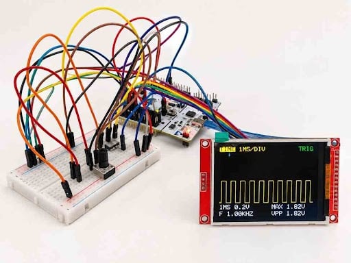
Once powered, the scope shows a splash screen for two seconds and then starts displaying the built-in 1 kHz test signal. Turning the knob changes the selected setting, pressing the knob moves to the next setting, and the two buttons freeze or capture the display.
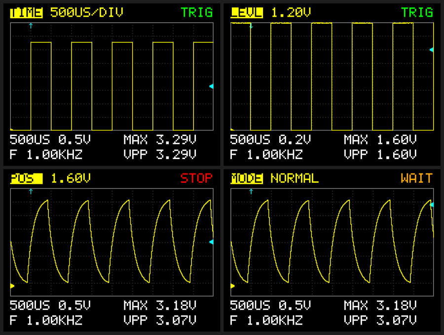
In Reading the screen, the top-left shows the setting the knob is changing, and the top-right shows the status (TRIG, AUTO, WAIT, ARM or STOP). The yellow marker on the left edge marks 0 V, the cyan marker on the right edge marks the trigger level, and the cyan arrow at the top marks the trigger point and edge direction. The bottom lines show the time base, volts per division, frequency, maximum voltage and peak-to-peak voltage.
Control | Function |
| Rotary knob, turn | Change the selected setting |
| Rotary knob, press | Next setting: TIME → VOLT → POS → LEVL → EDGE → MODE |
| RUN/STOP button | Freeze or resume the display |
| SINGLE button | Capture one triggered event and stop |
| Blue USER button | Test signal: 100 Hz → 1 kHz → 5 kHz |
Demonstrations
Amplitude and frequency, turning the potentiometer changes the height of the square wave and the VPP reading, while the frequency stays at 1.00 kHz. Pressing the USER button switches the test signal to 5 kHz, and the frequency reading follows.
Op-amp slew rate, at 50 µs/div, the rising edge of the square wave is a visible slope rather than a vertical line. This is the MCP6002's slew rate of 0.6 V/µs from its datasheet: rising 3.3 V takes about 5.5 µs. It also sets the practical bandwidth of this scope at about 50 kHz.
Aliasing, at 20 ms/div, the scope samples only 1,500 times per second, less than twice the 1 kHz test signal. The picture becomes confused, and the frequency reads about 500 Hz, a clear demonstration of the Nyquist sampling rule.
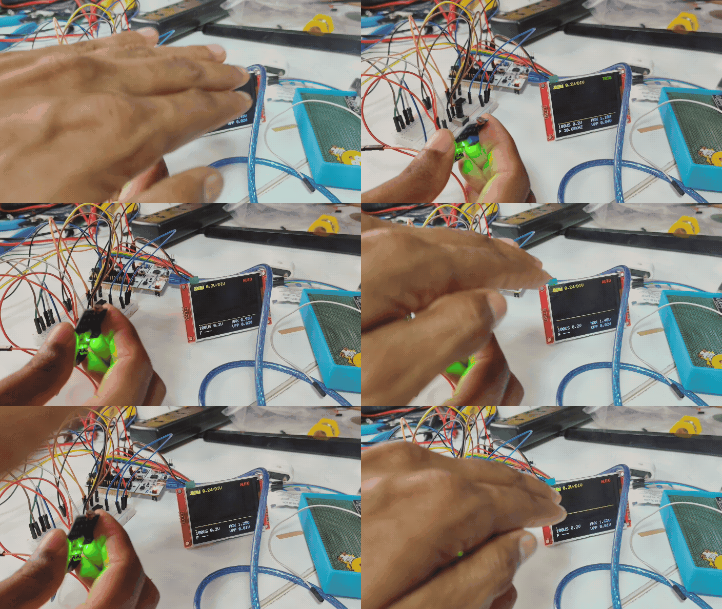
Light sensor, with an LDR module connected to the op-amp input (VCC to 3V3, AO to MCP6002 pin 3), covering the sensor or shining a torch moves the trace. Using SINGLE with a trigger level just below the normal line captures the moment a hand passes over the sensor.
Learning Experience and Platform Exploration
The biggest lesson from this project was that an oscilloscope is mostly about timing, not drawing. The first version read the ADC in continuous mode and displayed whatever arrived. It looked like a waveform, but the time axis was wrong: the ADC was running at about 219,000 samples per second, so the screen labelled "1 ms/div" was really showing about 46 µs per division. Moving the sampling clock to a hardware timer, and letting the timer trigger each conversion, made every TIME/DIV setting exact.
The STM32F411's peripherals turned out to be the real strength of the platform. Instead of the CPU polling the ADC or counting encoder pulses, three timers and the DMA controller run in the background: TIM2 paces the ADC, DMA fills the buffer, TIM1 decodes the knob, and TIM3 produces the test signal. The CPU only analyses a finished buffer and draws the frame. Setting up the timers with a few register writes, rather than through CubeMX, also made it clear what each bit does.
The display taught a second lesson: SPI bandwidth is limited, so how you draw matters. Sending pixels one at a time with a separate address window for each was far too slow for a live trace. Building full rows in RAM and streaming them in one transfer, at 21 MHz SPI, brought a full graph refresh down to about 43 ms. Drawing the grid, markers and trace together in the same pass also removed the flicker and grid damage seen in early versions.
Finally, the analog side was a reminder to read the datasheet. The MCP6002's 0.6 V/µs slew rate shows up directly on the screen at 50 µs/div, and its input limits define what can safely be connected. That is why the input is limited to 0–3.3 V until a proper protected front end is added.
STM32 Oscilloscope GitHub Repository
The complete STM32CubeIDE project, including the display driver, the circuit diagram and a README with setup steps, is available on GitHub. https://github.com/ImpulseTechy/DIY-OSCILLOSCOPE.git
File | Contents |
| Core/Src/main.c | Oscilloscope application: acquisition, trigger, measurements, rendering, controls |
| Core/Src/ili9341.c | ILI9341 display driver: initialisation, fast block drawing, text in three sizes |
| Core/Inc/ili9341.h | Driver header: commands, RGB565 colours, function prototypes |
| Core/Src/stm32f4xx_hal_msp.c | CubeMX peripheral setup, with the ADC DMA set to normal (one-shot) mode |
| Wiring_Diagram.png | Full-resolution circuit diagram |
To use it, create a CubeMX project for the NUCLEO-F411RE with ADC1 IN0 + DMA2 Stream 0, SPI2 (full-duplex master) and GPIO outputs PB12 TFT_CS, PB1 TFT_DC and PB2 TFT_RESET, generate the code, then replace or add the four source files above. Do not regenerate code after replacing main.c, because it has no CubeMX user-code sections.
Design Refinement and Optimization
Improvements made during development:
Hardware-timed sampling, TIM2 triggers every ADC conversion, so all nine time bases from 50 µs/div to 20 ms/div are exact.
One-shot DMA snapshots, each frame captures 600 samples and stops, so the buffer is never overwritten while it is being drawn.
- Faster SPI, the SPI2 prescaler was reduced from 8 to 2, raising the clock from about 5.25 MHz to 21 MHz.
- Row-based rendering, the graph is sent as 160 rows of 600 bytes, instead of one address window per pixel.
- Fast text, each character cell is built in RAM and sent in one transfer, in three sizes.
- Edge trigger with hysteresis, adjustable level and rising or falling edge, with AUTO, NORMAL and SINGLE modes.
- Hardware encoder decoding, TIM1 counts the knob in the background, so no clicks are lost while drawing.
- Built-in test signal, a known square wave on PA6 makes the scope self-test.
Possible next steps:
- A protected BNC input stage with ×1/×10 attenuation, AC/DC coupling and clamp diodes for real-world signals
- A second channel using the spare op-amp B of the MCP6002 on PA1
- A roll mode with slower time bases for sensor signals
- An FFT spectrum view using the CMSIS-DSP library
- SPI transfers through DMA for a higher frame rate
Complete Project Code
Below is the complete main.c for the STM32 oscilloscope, split into two parts for readability; copy both parts into one file. It compiles with 0 errors and 0 warnings in STM32CubeIDE against the STM32Cube FW_F4 HAL. The display driver (ili9341.c / ili9341.h) is available in the GitHub repository.


Complete Project Code
/* ============================================================
* STM32 DIY OSCILLOSCOPE - v2 (front-panel controls)
*
* Board : NUCLEO-F411RE (STM32F411RE @ 84 MHz)
* Display : 2.8" ILI9341 320x240 on SPI2
* Input : PA0 / ADC1_IN0 (MCP6002 voltage follower -> 1k -> PA0)
*
* CONTROLS
* Rotary encoder TURN -> change the selected setting
* Rotary encoder PRESS -> select next setting:
* TIME > VOLTS > POS > LEVEL > EDGE > MODE
* Button RUN/STOP -> freeze / unfreeze the screen
* Button SINGLE -> capture ONE triggered event, then stop
* Blue USER button -> test signal 100 Hz / 1 kHz / 5 kHz
*
* WIRING (all buttons connect the pin to GND when pressed;
* the STM32 internal pull-ups are used)
* Encoder CLK -> D7 (PA8, TIM1_CH1)
* Encoder DT -> D8 (PA9, TIM1_CH2)
* Encoder SW -> D6 (PB10)
* Encoder + -> 3V3 (NOT 5V)
* Encoder GND -> GND
* RUN/STOP -> D5 (PB4) and GND
* SINGLE -> D4 (PB5) and GND
* Test signal -> D12 (PA6) 1 kHz square wave (unchanged)
*
* HOW ONE FRAME WORKS (unchanged from v1)
* 1. ACQUIRE TIM2 paces the ADC, DMA fills adc_buffer[600]
* 2. ANALYZE min / max / frequency / trigger point
* 3. DRAW graph painted row by row + text
* ============================================================ */
#include "main.h"
#include "ili9341.h"
#include <stdio.h>
#include <string.h>
/* ============================================================
* PERIPHERAL HANDLES
* ============================================================ */
ADC_HandleTypeDef hadc1;
DMA_HandleTypeDef hdma_adc1;
SPI_HandleTypeDef hspi2;
UART_HandleTypeDef huart2;
/* ============================================================
* SCREEN LAYOUT (landscape 320 x 240)
* ============================================================ */
#define GRAPH_X 10
#define GRAPH_Y 28
#define GRAPH_WIDTH 300 /* 10 divisions x 30 px */
#define GRAPH_HEIGHT 160 /* 8 divisions x 20 px */
#define DIV_PIXELS_X 30
#define DIV_PIXELS_Y 20
#define TEXT_SIZE 2 /* 12 x 16 pixel characters */
#define TEXT_TOP_Y 6
#define TEXT_LINE1_Y 194
#define TEXT_LINE2_Y 216
#define TEXT_RIGHT_X 178
#define STATUS_X 262
/* ============================================================
* COLORS (RGB565)
* ============================================================ */
#define COLOR_BG ILI9341_BLACK
#define COLOR_GRID ILI9341_DARKGRAY
#define COLOR_BORDER ILI9341_GRAY
#define COLOR_TRACE ILI9341_YELLOW
#define COLOR_TRIGGER ILI9341_CYAN
#define COLOR_TEXT ILI9341_WHITE
#define COLOR_OK ILI9341_GREEN
#define COLOR_WARN ILI9341_ORANGE
#define COLOR_STOP ILI9341_RED
#define SPLASH_TITLE "DIY OSCILLOSCOPE"
/* ============================================================
* ADC / ACQUISITION
* ============================================================ */
#define ADC_MAX_COUNT 4095
#define ADC_VREF_MV 3300
#define SAMPLE_COUNT 600 /* 2 screens of samples */
#define TRIGGER_X 30 /* trigger point = 1st grid line */
#define MIN_SIGNAL_COUNTS 50 /* ~40 mV p-p: smaller = flat line */
#define TIMER_CLOCK_MHZ 84 /* TIM2 / TIM3 clock */
/* ============================================================
* ROTARY ENCODER
*
* TIM1 in "encoder mode" counts the CLK/DT pulses in hardware.
* Most KY-040 style encoders give 4 counts per click.
* - one click changes the value by TWO steps -> set it to 8
* - you need TWO clicks for one step -> set it to 2
* - clockwise goes the wrong way -> set REVERSE to 1
* ============================================================ */
#define ENCODER_COUNTS_PER_CLICK 4
#define ENCODER_REVERSE 0
/* ============================================================
* BUTTON PINS (encoder CLK/DT pins are set in Encoder_Init)
* ============================================================ */
#define ENC_SW_PORT GPIOB
#define ENC_SW_PIN GPIO_PIN_10 /* D6 */
#define RUNSTOP_PORT GPIOB
#define RUNSTOP_PIN GPIO_PIN_4 /* D5 */
#define SINGLE_PORT GPIOB
#define SINGLE_PIN GPIO_PIN_5 /* D4 */
/* ============================================================
* SETTINGS TABLES
* ============================================================ */
/* ---- Time base: 30 samples per division ---- */
typedef struct
{
uint32_t us_per_div;
const char *label;
} TimeBase;
static const TimeBase timebases[] =
{
{ 50, "50US" },
{ 100, "100US" },
{ 200, "200US" },
{ 500, "500US" },
{ 1000, "1MS" },
{ 2000, "2MS" },
{ 5000, "5MS" },
{ 10000, "10MS" },
{ 20000, "20MS" },
};
#define TIMEBASE_COUNT (sizeof(timebases) / sizeof(timebases[0]))
/* ---- Volts per division ---- */
typedef struct
{
uint32_t mv_per_div;
const char *label;
} VoltScale;
static const VoltScale voltscales[] =
{
{ 100, "0.1V" },
{ 200, "0.2V" },
{ 500, "0.5V" },
{ 1000, "1V" },
};
#define VOLTSCALE_COUNT (sizeof(voltscales) / sizeof(voltscales[0]))
/* ---- Test signal frequencies (blue button) ---- */
static const uint32_t test_freqs[] = { 100, 1000, 5000 };
#define TEST_FREQ_COUNT (sizeof(test_freqs) / sizeof(test_freqs[0]))
/* ---- Position / level limits (millivolts) ---- */
#define POS_MIN_MV -1000
#define POS_MAX_MV 4300
#define POS_STEP_MV 100
#define LEVEL_MAX_MV 3200
#define LEVEL_STEP_MV 100
#define LEVEL_AUTO 0 /* 0 = automatic (50 % of signal) */
/* ============================================================
* SCOPE STATE
* ============================================================ */
typedef enum { MENU_TIME, MENU_VOLTS, MENU_POS, MENU_LEVEL,
MENU_EDGE, MENU_MODE, MENU_COUNT } MenuItem;
typedef enum { STATE_RUN, STATE_STOP, STATE_ARMED } RunState;
typedef struct
{
uint8_t timebase; /* index into timebases[] */
uint8_t volts; /* index into voltscales[] */
int32_t center_mv; /* voltage shown on the middle line */
int32_t level_mv; /* trigger level, LEVEL_AUTO = auto */
uint8_t falling_edge; /* 0 = rising, 1 = falling */
uint8_t normal_mode; /* 0 = AUTO, 1 = NORMAL */
uint8_t test_freq; /* index into test_freqs[] */
} Settings;
static Settings settings =
{
.timebase = 3, /* 500 us/div */
.volts = 2, /* 0.5 V/div */
.center_mv = 2000, /* 0 V sits on the bottom line */
.level_mv = LEVEL_AUTO,
.falling_edge = 0,
.normal_mode = 0,
.test_freq = 1, /* 1 kHz */
};
static MenuItem menu = MENU_TIME;
static RunState runstate = STATE_RUN;
/* "something changed" flags set by the controls */
static volatile uint8_t menu_dirty = 1; /* redraw top bar */
static volatile uint8_t view_dirty = 0; /* redraw frozen waveform */
static volatile uint8_t status_dirty = 1; /* redraw status word */
static volatile uint8_t abort_capture = 0; /* STOP pressed mid-capture */
/* ============================================================
* SAMPLE BUFFERS
*
* adc_buffer : DMA writes here while capturing
* display_buffer : copy of the last GOOD frame (what is on screen)
* -> lets STOP / WAIT keep the picture while we
* keep capturing or re-draw with new settings
* ============================================================ */
static uint16_t adc_buffer[SAMPLE_COUNT];
static uint16_t display_buffer[SAMPLE_COUNT];
static uint32_t display_ticks = 0; /* TIM2 period of that frame */
static uint8_t have_frame = 0;
static volatile uint8_t acquisition_done = 0;
typedef struct
{
uint16_t min_count;
uint16_t max_count;
int16_t trigger_index; /* -1 = no trigger found */
uint16_t trigger_count; /* ADC level used for triggering */
uint32_t freq_mhz; /* frequency in milli-hertz, 0 = n/a */
} ScopeResult;
static ScopeResult display_result;
/* ============================================================
* FUNCTION PROTOTYPES
* ============================================================ */
void SystemClock_Config(void);
static void MX_GPIO_Init(void);
static void MX_DMA_Init(void);
static void MX_ADC1_Init(void);
static void MX_USART2_UART_Init(void);
static void MX_SPI2_Init(void);
static void SampleTimer_Init(void);
static void TestSignal_Init(void);
static void TestSignal_SetFrequency(uint32_t hz);
static void Controls_Init(void);
static void Controls_Poll(void);
static uint32_t Scope_Acquire(void);
static void Scope_Analyze(const uint16_t *buf, uint32_t ticks, ScopeResult *r);
static void Scope_DrawGraph(void);
static void Scope_DrawMenu(void);
static void Scope_DrawStatus(uint8_t triggered);
static void Scope_DrawReadouts(void);
/* ============================================================
* SMALL HELPERS
* ============================================================ */
static int32_t CountToMillivolts(int32_t count)
{
return (count * ADC_VREF_MV) / ADC_MAX_COUNT;
}
static int32_t MillivoltsToCount(int32_t mv)
{
if (mv < 0) mv = 0;
if (mv > ADC_VREF_MV) mv = ADC_VREF_MV;
return (mv * ADC_MAX_COUNT) / ADC_VREF_MV;
}
/*
* Voltage -> graph row, using the current VOLTS/DIV and POSITION.
* middle row (80) = settings.center_mv
* 20 px up = + 1 division
* Returns -1 if the voltage is above the graph, GRAPH_HEIGHT if below
* (callers clamp or skip as needed).
*/
static int32_t MillivoltsToRow(int32_t mv)
{
int32_t mv_per_div = voltscales[settings.volts].mv_per_div;
int32_t offset_px = ((mv - settings.center_mv) * DIV_PIXELS_Y) / mv_per_div;
int32_t row = (GRAPH_HEIGHT / 2) - offset_px;
if (row < -1) row = -1;
if (row > GRAPH_HEIGHT) row = GRAPH_HEIGHT;
return row;
}
static int32_t ClampRow(int32_t row)
{
if (row < 0) return 0;
if (row > GRAPH_HEIGHT - 1) return GRAPH_HEIGHT - 1;
return row;
}
/* signed "-1.25V" / "3.30V" text */
static void FormatVolts(char *out, size_t len, int32_t mv)
{
const char *sign = "";
if (mv < 0) { sign = "-"; mv = -mv; }
snprintf(out, len, "%s%lu.%02luV", sign,
(unsigned long)(mv / 1000),
(unsigned long)((mv % 1000) / 10));
}
/* ============================================================
* MAIN
* ============================================================ */
int main(void)
{
HAL_Init();
SystemClock_Config();
MX_GPIO_Init();
MX_DMA_Init();
MX_ADC1_Init();
MX_USART2_UART_Init();
MX_SPI2_Init();
SampleTimer_Init(); /* TIM2 = ADC sample clock */
TestSignal_Init(); /* TIM3 = test square wave */
Controls_Init(); /* TIM1 encoder + buttons */
/* ---------------- DISPLAY + SPLASH ---------------- */
ILI9341_Init();
ILI9341_SetRotation(1);
ILI9341_FillScreen(COLOR_BG);
ILI9341_DrawStringSize(64, 80, SPLASH_TITLE, COLOR_TRACE, COLOR_BG, 2);
ILI9341_DrawStringSize(103, 110, "STM32F411 + ILI9341",
COLOR_TEXT, COLOR_BG, 1);
ILI9341_DrawStringSize(61, 140, "KNOB: TURN = CHANGE PRESS = NEXT",
ILI9341_GRAY, COLOR_BG, 1);
ILI9341_DrawStringSize(67, 155, "RUN/STOP SINGLE BLUE = TEST",
ILI9341_GRAY, COLOR_BG, 1);
HAL_Delay(2000);
ILI9341_FillScreen(COLOR_BG);
Scope_DrawGraph(); /* empty grid */
/* ---------------- OSCILLOSCOPE LOOP ---------------- */
while (1)
{
Controls_Poll();
if (menu_dirty)
{
menu_dirty = 0;
Scope_DrawMenu();
}
/* ------------ STOPPED: only redraw on setting changes ------ */
if (runstate == STATE_STOP)
{
if (view_dirty)
{
view_dirty = 0;
if (have_frame)
{
Scope_Analyze(display_buffer, display_ticks,
&display_result);
}
Scope_DrawGraph();
Scope_DrawReadouts();
}
if (status_dirty)
{
status_dirty = 0;
Scope_DrawStatus(0);
}
HAL_Delay(5);
continue;
}
/* ------------ RUN or ARMED: capture a new frame ------------ */
abort_capture = 0;
uint32_t ticks = Scope_Acquire();
if (abort_capture) /* STOP pressed while capturing */
{
continue;
}
ScopeResult r;
Scope_Analyze(adc_buffer, ticks, &r);
uint8_t triggered = (r.trigger_index >= 0);
/* Keep this frame?
* RUN + AUTO : always
* RUN + NORMAL : only if triggered (else keep old picture)
* ARMED : only if triggered, then STOP */
uint8_t keep = triggered ||
(runstate == STATE_RUN && !settings.normal_mode);
if (keep)
{
memcpy(display_buffer, adc_buffer, sizeof(adc_buffer));
display_ticks = ticks;
display_result = r;
have_frame = 1;
if (runstate == STATE_ARMED)
{
runstate = STATE_STOP; /* single shot captured */
}
Scope_DrawGraph();
Scope_DrawReadouts();
HAL_GPIO_TogglePin(LD2_GPIO_Port, LD2_Pin);
}
else if (view_dirty && have_frame)
{
/* waiting for a trigger but the user moved POS / VOLTS:
redraw the held picture with the new view */
Scope_Analyze(display_buffer, display_ticks, &display_result);
Scope_DrawGraph();
Scope_DrawReadouts();
}
view_dirty = 0;
Scope_DrawStatus(triggered);
status_dirty = 0;
}
}
/* ============================================================
* 1. ACQUIRE (same as v1, plus "abort" when STOP is pressed)
* ============================================================ */
static uint32_t Scope_Acquire(void)
{
uint32_t us = timebases[settings.timebase].us_per_div;
uint32_t ticks = (TIMER_CLOCK_MHZ * us) / DIV_PIXELS_X;
acquisition_done = 0;
TIM2->CR1 &= ~TIM_CR1_CEN;
TIM2->CNT = 0;
TIM2->ARR = ticks - 1;
HAL_ADC_Start_DMA(&hadc1, (uint32_t *)adc_buffer, SAMPLE_COUNT);
TIM2->CR1 |= TIM_CR1_CEN;
uint32_t start = HAL_GetTick();
while (!acquisition_done)
{
Controls_Poll(); /* buttons stay responsive */
if (abort_capture || HAL_GetTick() - start > 2000)
{
break;
}
}
TIM2->CR1 &= ~TIM_CR1_CEN;
HAL_ADC_Stop_DMA(&hadc1);
return ticks;
}
void HAL_ADC_ConvCpltCallback(ADC_HandleTypeDef *hadc)
{
if (hadc->Instance == ADC1)
{
TIM2->CR1 &= ~TIM_CR1_CEN;
acquisition_done = 1;
}
}
void HAL_ADC_ErrorCallback(ADC_HandleTypeDef *hadc)
{
if (hadc->Instance == ADC1)
{
TIM2->CR1 &= ~TIM_CR1_CEN;
acquisition_done = 1;
}
}
/* ============================================================
* 2. ANALYZE
*
* a) min / max
* b) FREQUENCY: count crossings of the 50 % level (always auto,
* so the frequency reading works whatever LEVEL you choose)
* c) TRIGGER: first crossing of the chosen LEVEL in the chosen
* direction (EDGE) that leaves room for a full screen.
* Hysteresis = 1/8 of the signal height, so noise near the
* level does not cause false triggers.
* ============================================================ */
static void Scope_Analyze(const uint16_t *buf, uint32_t ticks, ScopeResult *r)
{
uint16_t min = 0xFFFF, max = 0;
for (int i = 0; i < SAMPLE_COUNT; i++)
{
if (buf[i] < min) min = buf[i];
if (buf[i] > max) max = buf[i];
}
r->min_count = min;
r->max_count = max;
r->trigger_index = -1;
r->freq_mhz = 0;
int32_t mid = (min + max) / 2;
int32_t hyst = (max - min) / 8;
if (hyst < 8) hyst = 8;
int32_t level = (settings.level_mv == LEVEL_AUTO)
? mid
: MillivoltsToCount(settings.level_mv);
r->trigger_count = (uint16_t)level;
uint8_t flat = (max - min < MIN_SIGNAL_COUNTS);
/* ---- frequency (rising crossings of the 50 % level) ---- */
if (!flat)
{
uint8_t armed = 0;
int32_t first = -1, last = -1, edges = 0;
for (int32_t i = 0; i < SAMPLE_COUNT; i++)
{
if (buf[i] < mid - hyst) armed = 1;
else if (armed && buf[i] >= mid)
{
armed = 0;
edges++;
if (first < 0) first = i;
last = i;
}
}
if (edges >= 2 && last > first)
{
uint64_t num = (uint64_t)TIMER_CLOCK_MHZ * 1000000ULL
* 1000ULL * (uint64_t)(edges - 1);
uint64_t den = (uint64_t)ticks * (uint64_t)(last - first);
r->freq_mhz = (uint32_t)(num / den);
}
}
/* ---- trigger ---- */
if (flat && settings.level_mv == LEVEL_AUTO)
{
return; /* nothing to trigger on */
}
const int32_t latest = SAMPLE_COUNT - GRAPH_WIDTH + TRIGGER_X;
uint8_t armed = 0;
for (int32_t i = 0; i <= latest; i++)
{
int32_t s = buf[i];
if (!settings.falling_edge)
{
/* RISING: be below (level - hyst), then reach level */
if (s < level - hyst) armed = 1;
else if (armed && s >= level && i >= TRIGGER_X)
{
r->trigger_index = (int16_t)i;
return;
}
}
else
{
/* FALLING: be above (level + hyst), then drop to level */
if (s > level + hyst) armed = 1;
else if (armed && s <= level && i >= TRIGGER_X)
{
r->trigger_index = (int16_t)i;
return;
}
}
}
}
/* ============================================================
* 3a. DRAW THE GRAPH (row by row, like v1)
*
* Markers:
* left edge, yellow ">" = 0 V (ground) of CH1
* right edge, cyan "<" = trigger level
* top, cyan arrow = trigger point + edge direction
* ============================================================ */
static void Scope_DrawGraph(void)
{
static uint8_t trace_top[GRAPH_WIDTH];
static uint8_t trace_bottom[GRAPH_WIDTH];
static uint8_t row_pixels[GRAPH_WIDTH * 2];
const ScopeResult *r = &display_result;
uint8_t triggered = have_frame && (r->trigger_index >= 0);
int32_t first = triggered ? (r->trigger_index - TRIGGER_X) : 0;
/* ---- sample -> vertical span per column ---- */
if (have_frame)
{
int32_t prev = ClampRow(MillivoltsToRow(
CountToMillivolts(display_buffer[first])));
for (int x = 0; x < GRAPH_WIDTH; x++)
{
int32_t row = ClampRow(MillivoltsToRow(
CountToMillivolts(display_buffer[first + x])));
trace_top[x] = (row < prev) ? row : prev;
trace_bottom[x] = (row > prev) ? row : prev;
prev = row;
}
}
else
{
for (int x = 0; x < GRAPH_WIDTH; x++)
{
trace_top[x] = 255; /* no trace */
trace_bottom[x] = 0;
}
}
/* ---- marker rows ---- */
int32_t ground_row = MillivoltsToRow(0);
int32_t level_row = -100;
if (settings.level_mv != LEVEL_AUTO)
{
level_row = MillivoltsToRow(settings.level_mv);
}
else if (have_frame && r->max_count - r->min_count >= MIN_SIGNAL_COUNTS)
{
level_row = MillivoltsToRow(CountToMillivolts(r->trigger_count));
}
/* ---- paint ---- */
ILI9341_StartPixels(GRAPH_X, GRAPH_Y, GRAPH_WIDTH, GRAPH_HEIGHT);
for (int y = 0; y < GRAPH_HEIGHT; y++)
{
uint8_t border_row = (y == 0 || y == GRAPH_HEIGHT - 1);
uint8_t grid_row = (y % DIV_PIXELS_Y == 0);
uint8_t dot_row = (y % 4 == 0);
int32_t dg = y - ground_row; if (dg < 0) dg = -dg;
int32_t dl = y - level_row; if (dl < 0) dl = -dl;
for (int x = 0; x < GRAPH_WIDTH; x++)
{
uint16_t color = COLOR_BG;
if (border_row || x == 0 || x == GRAPH_WIDTH - 1)
color = COLOR_BORDER;
else if ((x % DIV_PIXELS_X == 0) && dot_row)
color = COLOR_GRID;
else if (grid_row && (x % 4 == 0))
color = COLOR_GRID;
/* ground marker > at the left edge */
if (x < 6 && dg <= 3 - x / 2)
color = COLOR_TRACE;
/* trigger level marker < at the right edge */
if (x >= GRAPH_WIDTH - 6 && dl <= 3 - (GRAPH_WIDTH - 1 - x) / 2)
color = COLOR_TRIGGER;
/* trigger point arrow at the top (up = rising) */
if (triggered)
{
int32_t dx = x - TRIGGER_X;
if (dx < 0) dx = -dx;
if (dx == 0 && y >= 1 && y <= 8)
color = COLOR_TRIGGER;
else if (dx <= 2 && dx > 0)
{
int32_t head = settings.falling_edge ? (8 - dx) : (1 + dx);
if (y == head) color = COLOR_TRIGGER;
}
}
/* the waveform itself, on top of everything */
if (y >= trace_top[x] && y <= trace_bottom[x])
color = COLOR_TRACE;
row_pixels[x * 2] = color >> 8;
row_pixels[x * 2 + 1] = color & 0xFF;
}
ILI9341_PushPixels(row_pixels, sizeof(row_pixels));
}
ILI9341_EndPixels();
}
/* ============================================================
* 3b. TOP BAR = the setting the knob is changing
*
* [TIME] 500US/DIV
* ^^^^^^ highlighted name, value in yellow
* ============================================================ */
static void Scope_DrawMenu(void)
{
static const char *names[MENU_COUNT] =
{ "TIME", "VOLT", "POS", "LEVL", "EDGE", "MODE" };
char value[16];
switch (menu)
{
case MENU_TIME:
snprintf(value, sizeof(value), "%s/DIV",
timebases[settings.timebase].label);
break;
case MENU_VOLTS:
snprintf(value, sizeof(value), "%s/DIV",
voltscales[settings.volts].label);
break;
case MENU_POS:
FormatVolts(value, sizeof(value), settings.center_mv);
break;
case MENU_LEVEL:
if (settings.level_mv == LEVEL_AUTO)
snprintf(value, sizeof(value), "AUTO");
else
FormatVolts(value, sizeof(value), settings.level_mv);
break;
case MENU_EDGE:
snprintf(value, sizeof(value),
settings.falling_edge ? "FALLING" : "RISING");
break;
default: /* MENU_MODE */
snprintf(value, sizeof(value),
settings.normal_mode ? "NORMAL" : "AUTO");
break;
}
char name[6];
snprintf(name, sizeof(name), "%-4s", names[menu]);
char padded[20];
snprintf(padded, sizeof(padded), " %-9s", value);
padded[10] = '\0'; /* fixed width */
/* name: black text on yellow = "selected" */
ILI9341_DrawStringSize(GRAPH_X, TEXT_TOP_Y, name,
COLOR_BG, COLOR_TRACE, TEXT_SIZE);
ILI9341_DrawStringSize(GRAPH_X + 4 * 6 * TEXT_SIZE, TEXT_TOP_Y, padded,
COLOR_TRACE, COLOR_BG, TEXT_SIZE);
}
/* ============================================================
* 3c. STATUS WORD (top right)
*
* TRIG green running, triggered
* AUTO orange running, no trigger (AUTO mode draws anyway)
* WAIT orange running, NORMAL mode, waiting for a trigger
* ARM yellow SINGLE pressed, waiting for one trigger
* STOP red frozen
* ============================================================ */
static void Scope_DrawStatus(uint8_t triggered)
{
const char *word;
uint16_t color;
if (runstate == STATE_STOP) { word = "STOP"; color = COLOR_STOP; }
else if (runstate == STATE_ARMED) { word = "ARM "; color = COLOR_TRACE; }
else if (triggered) { word = "TRIG"; color = COLOR_OK; }
else if (settings.normal_mode) { word = "WAIT"; color = COLOR_WARN; }
else { word = "AUTO"; color = COLOR_WARN; }
ILI9341_DrawStringSize(STATUS_X, TEXT_TOP_Y, word,
color, COLOR_BG, TEXT_SIZE);
}
/* ============================================================
* 3d. BOTTOM READOUTS
*
* 500US 0.5V MAX 3.29V
* F 1.00KHZ VPP 3.29V
* ============================================================ */
static void Scope_DrawReadouts(void)
{
const ScopeResult *r = &display_result;
char text[24];
char volts[12];
/* ---- settings summary ---- */
snprintf(text, sizeof(text), "%s %s ",
timebases[settings.timebase].label,
voltscales[settings.volts].label);
text[11] = '\0';
ILI9341_DrawStringSize(GRAPH_X, TEXT_LINE1_Y, text,
COLOR_TEXT, COLOR_BG, TEXT_SIZE);
if (!have_frame)
{
return;
}
/* ---- MAX ---- */
FormatVolts(volts, sizeof(volts), CountToMillivolts(r->max_count));
snprintf(text, sizeof(text), "MAX %s ", volts);
text[10] = '\0';
ILI9341_DrawStringSize(TEXT_RIGHT_X, TEXT_LINE1_Y, text,
COLOR_TEXT, COLOR_BG, TEXT_SIZE);
/* ---- VPP ---- */
FormatVolts(volts, sizeof(volts),
CountToMillivolts(r->max_count - r->min_count));
snprintf(text, sizeof(text), "VPP %s ", volts);
text[10] = '\0';
ILI9341_DrawStringSize(TEXT_RIGHT_X, TEXT_LINE2_Y, text,
COLOR_TEXT, COLOR_BG, TEXT_SIZE);
/* ---- frequency ---- */
uint32_t mhz = r->freq_mhz;
if (mhz == 0)
snprintf(text, sizeof(text), "F --- ");
else if (mhz < 1000000)
snprintf(text, sizeof(text), "F %lu.%luHZ ",
(unsigned long)(mhz / 1000),
(unsigned long)((mhz % 1000) / 100));
else
{
uint32_t hz = mhz / 1000;
snprintf(text, sizeof(text), "F %lu.%02luKHZ ",
(unsigned long)(hz / 1000),
(unsigned long)((hz % 1000) / 10));
}
text[10] = '\0';
ILI9341_DrawStringSize(GRAPH_X, TEXT_LINE2_Y, text,
COLOR_TEXT, COLOR_BG, TEXT_SIZE);
}
/* ============================================================
* CONTROLS
* ============================================================ */
/* ---- Debounced push button (LOW = pressed) ---- */
typedef struct
{
GPIO_TypeDef *port;
uint16_t pin;
GPIO_PinState last;
uint32_t changed_at;
} Button;
static Button btn_encoder = { ENC_SW_PORT, ENC_SW_PIN, GPIO_PIN_SET, 0 };
static Button btn_runstop = { RUNSTOP_PORT, RUNSTOP_PIN, GPIO_PIN_SET, 0 };
static Button btn_single = { SINGLE_PORT, SINGLE_PIN, GPIO_PIN_SET, 0 };
static Button btn_blue = { B1_GPIO_Port, B1_Pin, GPIO_PIN_SET, 0 };
/* returns 1 exactly once per press */
static uint8_t Button_Pressed(Button *b)
{
GPIO_PinState now = HAL_GPIO_ReadPin(b->port, b->pin);
if (now != b->last && (HAL_GetTick() - b->changed_at) > 30)
{
b->last = now;
b->changed_at = HAL_GetTick();
return (now == GPIO_PIN_RESET);
}
return 0;
}
/* ---- Encoder: returns +n / -n clicks since last call ---- */
static int32_t Encoder_ReadClicks(void)
{
static uint16_t last_count = 0;
static int32_t remainder = 0;
uint16_t now = (uint16_t)TIM1->CNT;
int16_t diff = (int16_t)(now - last_count); /* handles wrap */
last_count = now;
remainder += diff;
int32_t clicks = remainder / ENCODER_COUNTS_PER_CLICK;
remainder -= clicks * ENCODER_COUNTS_PER_CLICK;
return ENCODER_REVERSE ? -clicks : clicks;
}
static int32_t Clamp(int32_t v, int32_t lo, int32_t hi)
{
return (v < lo) ? lo : (v > hi) ? hi : v;
}
/* ---- Apply knob clicks to the selected setting ---- */
static void Settings_Adjust(int32_t clicks)
{
switch (menu)
{
case MENU_TIME:
settings.timebase = Clamp(settings.timebase + clicks,
0, TIMEBASE_COUNT - 1);
break;
case MENU_VOLTS:
settings.volts = Clamp(settings.volts + clicks,
0, VOLTSCALE_COUNT - 1);
break;
case MENU_POS:
settings.center_mv = Clamp(settings.center_mv
+ clicks * POS_STEP_MV,
POS_MIN_MV, POS_MAX_MV);
break;
case MENU_LEVEL:
/* 0 = AUTO, then 0.10 V ... 3.20 V */
settings.level_mv = Clamp(settings.level_mv
+ clicks * LEVEL_STEP_MV,
LEVEL_AUTO, LEVEL_MAX_MV);
break;
case MENU_EDGE:
settings.falling_edge = !settings.falling_edge;
break;
default: /* MENU_MODE */
settings.normal_mode = !settings.normal_mode;
break;
}
menu_dirty = 1;
view_dirty = 1; /* re-draw frozen picture with new view */
status_dirty = 1;
}
/* ---- Called all the time from the main loop ---- */
static void Controls_Poll(void)
{
/* knob turn */
int32_t clicks = Encoder_ReadClicks();
if (clicks != 0)
{
Settings_Adjust(clicks);
}
/* knob press -> next menu item */
if (Button_Pressed(&btn_encoder))
{
menu = (MenuItem)((menu + 1) % MENU_COUNT);
menu_dirty = 1;
}
/* RUN / STOP */
if (Button_Pressed(&btn_runstop))
{
if (runstate == STATE_RUN)
{
runstate = STATE_STOP;
abort_capture = 1;
}
else
{
runstate = STATE_RUN; /* from STOP or ARMED */
}
status_dirty = 1;
}
/* SINGLE */
if (Button_Pressed(&btn_single))
{
runstate = STATE_ARMED;
status_dirty = 1;
}
/* Blue button -> next test signal frequency */
if (Button_Pressed(&btn_blue))
{
settings.test_freq = (settings.test_freq + 1) % TEST_FREQ_COUNT;
TestSignal_SetFrequency(test_freqs[settings.test_freq]);
}
}
/* ============================================================
* TIM1 ENCODER MODE + BUTTON PINS
*
* Encoder mode 3: TIM1 counts up/down on every edge of CLK and DT
* by itself (no interrupts, no missed steps). We just read CNT.
*
* PA8 = TIM1_CH1 (D7) <- CLK
* PA9 = TIM1_CH2 (D8) <- DT
* ============================================================ */
static void Controls_Init(void)
{
GPIO_InitTypeDef g = {0};
__HAL_RCC_GPIOA_CLK_ENABLE();
__HAL_RCC_GPIOB_CLK_ENABLE();
__HAL_RCC_TIM1_CLK_ENABLE();
/* Encoder CLK / DT */
g.Pin = GPIO_PIN_8 | GPIO_PIN_9;
g.Mode = GPIO_MODE_AF_PP;
g.Pull = GPIO_PULLUP;
g.Speed = GPIO_SPEED_FREQ_LOW;
g.Alternate = GPIO_AF1_TIM1;
HAL_GPIO_Init(GPIOA, &g);
/* Encoder SW, RUN/STOP, SINGLE: inputs with pull-up */
g.Pin = ENC_SW_PIN | RUNSTOP_PIN | SINGLE_PIN;
g.Mode = GPIO_MODE_INPUT;
g.Pull = GPIO_PULLUP;
g.Alternate = 0;
HAL_GPIO_Init(GPIOB, &g);
/* TIM1 as quadrature decoder */
TIM1->CR1 = 0;
TIM1->SMCR = TIM_SMCR_SMS_0 | TIM_SMCR_SMS_1; /* encoder mode 3 */
TIM1->CCMR1 = TIM_CCMR1_CC1S_0 | TIM_CCMR1_CC2S_0 /* TI1, TI2 inputs */
| (0xFU << TIM_CCMR1_IC1F_Pos) /* max filtering */
| (0xFU << TIM_CCMR1_IC2F_Pos);
TIM1->CCER = 0; /* no inversion */
TIM1->ARR = 0xFFFF;
TIM1->CNT = 0;
TIM1->CR1 = TIM_CR1_CEN;
}
/* ============================================================
* TIM2 = SAMPLE CLOCK FOR THE ADC (unchanged)
* ============================================================ */
static void SampleTimer_Init(void)
{
__HAL_RCC_TIM2_CLK_ENABLE();
TIM2->CR1 = 0;
TIM2->PSC = 0; /* 84 MHz */
TIM2->ARR = 1000 - 1; /* real value set per frame */
TIM2->CR2 = TIM_CR2_MMS_1; /* TRGO on update */
TIM2->EGR = TIM_EGR_UG;
TIM2->SR = 0;
}
/* ============================================================
* TIM3 CH1 = TEST SQUARE WAVE ON PA6 (D12)
* ============================================================ */
static void TestSignal_SetFrequency(uint32_t hz)
{
uint32_t period = 1000000UL / hz; /* timer ticks at 1 MHz */
TIM3->ARR = period - 1;
TIM3->CCR1 = period / 2; /* 50 % duty */
TIM3->EGR = TIM_EGR_UG;
}
static void TestSignal_Init(void)
{
GPIO_InitTypeDef GPIO_InitStruct = {0};
__HAL_RCC_GPIOA_CLK_ENABLE();
__HAL_RCC_TIM3_CLK_ENABLE();
GPIO_InitStruct.Pin = GPIO_PIN_6;
GPIO_InitStruct.Mode = GPIO_MODE_AF_PP;
GPIO_InitStruct.Pull = GPIO_NOPULL;
GPIO_InitStruct.Speed = GPIO_SPEED_FREQ_LOW;
GPIO_InitStruct.Alternate = GPIO_AF2_TIM3;
HAL_GPIO_Init(GPIOA, &GPIO_InitStruct);
TIM3->PSC = TIMER_CLOCK_MHZ - 1; /* 1 MHz tick */
TIM3->CCMR1 = (6U << TIM_CCMR1_OC1M_Pos) /* PWM mode 1 */
| TIM_CCMR1_OC1PE;
TIM3->CCER = TIM_CCER_CC1E;
TIM3->CR1 = TIM_CR1_ARPE;
TestSignal_SetFrequency(test_freqs[settings.test_freq]);
TIM3->CR1 |= TIM_CR1_CEN;
}
/* ============================================================
* ADC1 INITIALIZATION
*
* CHANGED from the potentiometer version:
* - Continuous mode OFF (TIM2 decides WHEN to sample)
* - External trigger = TIM2 TRGO, rising edge
* - DMA continuous OFF (one-shot buffer per frame)
* - Sampling time 15 cyc (fast enough for 600 kS/s)
* ============================================================ */
static void MX_ADC1_Init(void)
{
ADC_ChannelConfTypeDef sConfig = {0};
hadc1.Instance = ADC1;
hadc1.Init.ClockPrescaler = ADC_CLOCK_SYNC_PCLK_DIV4; /* 21 MHz */
hadc1.Init.Resolution = ADC_RESOLUTION_12B;
hadc1.Init.ScanConvMode = DISABLE;
hadc1.Init.ContinuousConvMode = DISABLE;
hadc1.Init.DiscontinuousConvMode = DISABLE;
hadc1.Init.ExternalTrigConvEdge = ADC_EXTERNALTRIGCONVEDGE_RISING;
hadc1.Init.ExternalTrigConv = ADC_EXTERNALTRIGCONV_T2_TRGO;
hadc1.Init.DataAlign = ADC_DATAALIGN_RIGHT;
hadc1.Init.NbrOfConversion = 1;
hadc1.Init.DMAContinuousRequests = DISABLE;
hadc1.Init.EOCSelection = ADC_EOC_SINGLE_CONV;
if (HAL_ADC_Init(&hadc1) != HAL_OK)
{
Error_Handler();
}
sConfig.Channel = ADC_CHANNEL_0; /* PA0 */
sConfig.Rank = 1;
sConfig.SamplingTime = ADC_SAMPLETIME_15CYCLES;
if (HAL_ADC_ConfigChannel(&hadc1, &sConfig) != HAL_OK)
{
Error_Handler();
}
}
/* ============================================================
* SPI2 INITIALIZATION (unchanged)
*
* APB1 = 42 MHz, prescaler 2 -> 21 MHz SPI clock.
* If the screen shows noise/garbage with long jumper wires,
* use SPI_BAUDRATEPRESCALER_4 (10.5 MHz).
* ============================================================ */
static void MX_SPI2_Init(void)
{
hspi2.Instance = SPI2;
hspi2.Init.Mode = SPI_MODE_MASTER;
hspi2.Init.Direction = SPI_DIRECTION_2LINES;
hspi2.Init.DataSize = SPI_DATASIZE_8BIT;
hspi2.Init.CLKPolarity = SPI_POLARITY_LOW;
hspi2.Init.CLKPhase = SPI_PHASE_1EDGE;
hspi2.Init.NSS = SPI_NSS_SOFT;
hspi2.Init.BaudRatePrescaler = SPI_BAUDRATEPRESCALER_2;
hspi2.Init.FirstBit = SPI_FIRSTBIT_MSB;
hspi2.Init.TIMode = SPI_TIMODE_DISABLE;
hspi2.Init.CRCCalculation = SPI_CRCCALCULATION_DISABLE;
hspi2.Init.CRCPolynomial = 10;
if (HAL_SPI_Init(&hspi2) != HAL_OK)
{
Error_Handler();
}
}
/* ============================================================
* USART2 INITIALIZATION (unchanged, ST-LINK virtual COM)
* ============================================================ */
static void MX_USART2_UART_Init(void)
{
huart2.Instance = USART2;
huart2.Init.BaudRate = 115200;
huart2.Init.WordLength = UART_WORDLENGTH_8B;
huart2.Init.StopBits = UART_STOPBITS_1;
huart2.Init.Parity = UART_PARITY_NONE;
huart2.Init.Mode = UART_MODE_TX_RX;
huart2.Init.HwFlowCtl = UART_HWCONTROL_NONE;
huart2.Init.OverSampling = UART_OVERSAMPLING_16;
if (HAL_UART_Init(&huart2) != HAL_OK)
{
Error_Handler();
}
}
/* ============================================================
* DMA INITIALIZATION (unchanged)
* ============================================================ */
static void MX_DMA_Init(void)
{
__HAL_RCC_DMA2_CLK_ENABLE();
HAL_NVIC_SetPriority(DMA2_Stream0_IRQn, 0, 0);
HAL_NVIC_EnableIRQ(DMA2_Stream0_IRQn);
}
/* ============================================================
* GPIO INITIALIZATION
*
* NEW: B1 user button (PC13) as input.
* ============================================================ */
static void MX_GPIO_Init(void)
{
GPIO_InitTypeDef GPIO_InitStruct = {0};
__HAL_RCC_GPIOA_CLK_ENABLE();
__HAL_RCC_GPIOB_CLK_ENABLE();
__HAL_RCC_GPIOC_CLK_ENABLE();
/* TFT control pins start HIGH (inactive) */
HAL_GPIO_WritePin(TFT_CS_GPIO_Port, TFT_CS_Pin, GPIO_PIN_SET);
HAL_GPIO_WritePin(TFT_DC_GPIO_Port, TFT_DC_Pin, GPIO_PIN_SET);
HAL_GPIO_WritePin(TFT_RESET_GPIO_Port, TFT_RESET_Pin, GPIO_PIN_SET);
GPIO_InitStruct.Pin = TFT_CS_Pin | TFT_DC_Pin | TFT_RESET_Pin;
GPIO_InitStruct.Mode = GPIO_MODE_OUTPUT_PP;
GPIO_InitStruct.Pull = GPIO_NOPULL;
GPIO_InitStruct.Speed = GPIO_SPEED_FREQ_VERY_HIGH;
HAL_GPIO_Init(GPIOB, &GPIO_InitStruct);
/* Onboard LED LD2 (PA5) - blinks once per frame */
GPIO_InitStruct.Pin = LD2_Pin;
GPIO_InitStruct.Mode = GPIO_MODE_OUTPUT_PP;
GPIO_InitStruct.Pull = GPIO_NOPULL;
GPIO_InitStruct.Speed = GPIO_SPEED_FREQ_LOW;
HAL_GPIO_Init(LD2_GPIO_Port, &GPIO_InitStruct);
/* Blue USER button B1 (PC13) - board has its own pull-up */
GPIO_InitStruct.Pin = B1_Pin;
GPIO_InitStruct.Mode = GPIO_MODE_INPUT;
GPIO_InitStruct.Pull = GPIO_NOPULL;
HAL_GPIO_Init(B1_GPIO_Port, &GPIO_InitStruct);
}
/* ============================================================
* SYSTEM CLOCK (unchanged)
*
* HSI 16 MHz / 16 x 336 / 4 = 84 MHz SYSCLK
* APB1 = 42 MHz (timers 84 MHz), APB2 = 84 MHz
* ============================================================ */
void SystemClock_Config(void)
{
RCC_OscInitTypeDef RCC_OscInitStruct = {0};
RCC_ClkInitTypeDef RCC_ClkInitStruct = {0};
__HAL_RCC_PWR_CLK_ENABLE();
__HAL_PWR_VOLTAGESCALING_CONFIG(PWR_REGULATOR_VOLTAGE_SCALE1);
RCC_OscInitStruct.OscillatorType = RCC_OSCILLATORTYPE_HSI;
RCC_OscInitStruct.HSIState = RCC_HSI_ON;
RCC_OscInitStruct.HSICalibrationValue = RCC_HSICALIBRATION_DEFAULT;
RCC_OscInitStruct.PLL.PLLState = RCC_PLL_ON;
RCC_OscInitStruct.PLL.PLLSource = RCC_PLLSOURCE_HSI;
RCC_OscInitStruct.PLL.PLLM = 16;
RCC_OscInitStruct.PLL.PLLN = 336;
RCC_OscInitStruct.PLL.PLLP = RCC_PLLP_DIV4;
RCC_OscInitStruct.PLL.PLLQ = 7;
if (HAL_RCC_OscConfig(&RCC_OscInitStruct) != HAL_OK)
{
Error_Handler();
}
RCC_ClkInitStruct.ClockType = RCC_CLOCKTYPE_HCLK
| RCC_CLOCKTYPE_SYSCLK
| RCC_CLOCKTYPE_PCLK1
| RCC_CLOCKTYPE_PCLK2;
RCC_ClkInitStruct.SYSCLKSource = RCC_SYSCLKSOURCE_PLLCLK;
RCC_ClkInitStruct.AHBCLKDivider = RCC_SYSCLK_DIV1;
RCC_ClkInitStruct.APB1CLKDivider = RCC_HCLK_DIV2;
RCC_ClkInitStruct.APB2CLKDivider = RCC_HCLK_DIV1;
if (HAL_RCC_ClockConfig(&RCC_ClkInitStruct, FLASH_LATENCY_2) != HAL_OK)
{
Error_Handler();
}
}
/* ============================================================
* ERROR HANDLER
* ============================================================ */
void Error_Handler(void)
{
__disable_irq();
while (1)
{
}
}

Add a comment
No account needed. Your comment appears once a moderator has reviewed it.