

Display advertising plays a very important role in marketing, and there are several advertising methods like newspapers, posters, glow signboards, etc.. Still, digital LED display boards are getting popular nowadays because of their reliability and advantages. Although they are a little expensive, they are durable and customizable. P10 LED display boards have emerged as the preferred choice for businesses seeking dynamic, customizable advertising solutions. For instance, the advertising text can be changed easily whenever needed, and it can also be used as a digital notice board in any public place. We previously used an 8x8 LED matrix with many boards to control the text displayed over it; today, we will use the P10 display with Arduino. This comprehensive guide will teach you how to make an LED display board using Arduino with a P10 LED matrix module, creating a professional-grade digital notice board perfect for commercial and educational applications.
In this tutorial, we are going to use a 32x16 LED dot Matrix display module, which is also known as a P10 LED Display Module, to display a scrolling text by using Arduino UNO. P10 modules can be cascaded to build any size of advertising board. P10 LED displays offer superior reliability, energy efficiency, and customisation capabilities compared to static signage.
Table of Contents
What is a P10 LED Matrix Module?
A P10 LED display module is a pixel matrix (32×16) with 512 high-brightness LEDs designed for outdoor and indoor advertising applications. The designation "P10" refers to the ten millimetre pixel pitch, or the distance between LED centres.
| Specification | Value |
| LED Configuration | 32 columns × 16 rows (512 LEDs) |
| Brightness | 3,500-4,500 nits |
| Power Consumption | 20W maximum |
| Input Voltage | DC 5V |
| Waterproof Rating | IP65 |
| Pixel Pitch | 10mm |
| Viewing Angle | High (160°+ horizontal/vertical) |
| Contrast Ratio | High contrast for outdoor visibility |
Required Components for Arduino P10 LED Display
- Arduino UNO-1
- 32*16 P10 LED display module-1
- 16 Pin FRC connector-1
- 5V DC,3 AMP SMPS
- Connectors
Working of a P10 LED Matrix Module
Understanding the P10 LED display pinout is crucial for successful implementation.
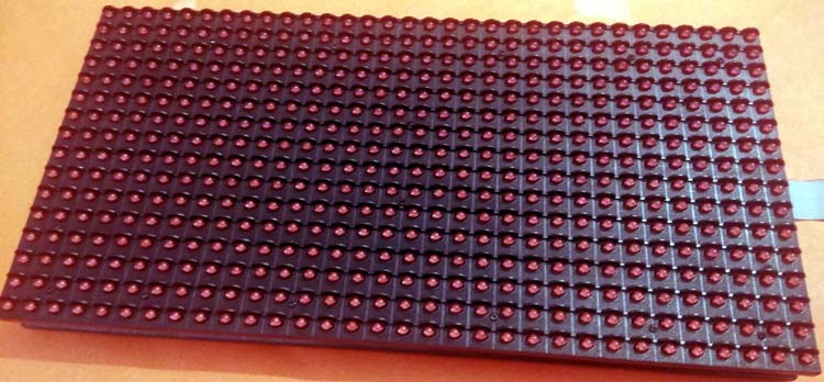
A P10 LED Display Module is the most suitable for designing any size of outdoor or indoor LED display advertisement board. This panel has a total of 512 high-brightness LEDs mounted on a plastic housing designed for the best display results. Any number of such panels can be combined in any row and column structures to design an attractive LED signboard.
The 32*16 module size means that there are 32 LEDs in each row and 16 LEDs in each column. So there is a total of 512 numbers of LEDs present in each module unit.
Features of a P10 LED Matrix Module:
- Brightness: 3500-4500nits
- Max Power Consumption: 20W
- Voltage Input: DC 5V
- IP65 Waterproof
- 1W Pixel Configuration
- High Viewing Angle
- High Contrast Ratio
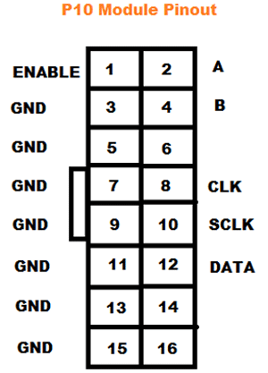
P10 LED Display Circuit Diagram and Pinout
- Enable: This pin is used to control the brightness of the LED panel by giving a PWM pulse to it.
- A, B: These are called multiplex select pins. They take digital input to select any multiplex rows.
- Shift clock (CLK), Store clock (SCLK) and Data: These are the normal shift register control pins. Here, a shift register 74HC595 is used.
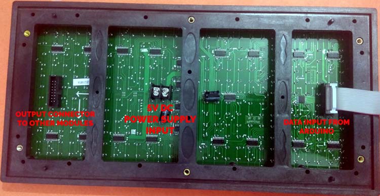
P10 LED Display Circuit Diagram Components
Complete circuit diagram for the P10 module with Arduino is given below:

Arduino UNO and P10 display modules are interconnected as per the pin mapping shown below:
P10 LED Module | Arduino UNO |
ENABLE | 9 |
A | 6 |
B | 7 |
CLK | 13 |
SCLK | 8 |
DATA | 11 |
GND | GND |
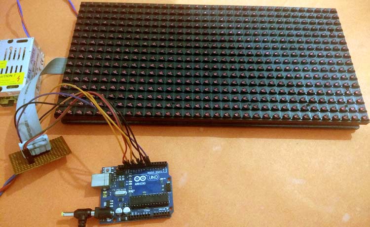
Note: Connect the Power terminal of the P10 module to a 5V DC SMPS separately. It is recommended to connect a 5V, 3 Amp DC power supply to a single unit of the P10 LED module. If you are planning to connect a larger number of modules, then increase your SMPS rating accordingly.
P10 LED Display Using Arduino Programming
After the successful completion of the hardware setup, it’s time to program the Arduino. Complete code for this 10 Led Display Arduino, along with the video, is given at the end of this tutorial. The stepwise description of the code is given below.
Before starting the P10 LED display using Arduino programming, install the required libraries.
First of all, include all the dependent libraries in the program. Here we are using “DMD.h” Library for P10 led operations, download this library from here and install it in Arduino IDE. After that, include the library for “TimerOne.h”, which will be used for interrupt tasks. This library can be downloaded from here.
Then, include all the required font libraries; in our case, we are using “Arial Black font” for the display.
#include <SPI.h>
#include <DMD.h>
#include <TimerOne.h>
#include "SystemFont5x7.h"
#include "Arial_black_16.h"
In the next step, define the number of rows and columns for the LED display board. In our case, we are using only one module, so the ROW value and the COLUMN value will be 1. Then define the font name- Arial_Black_16 for the text scrolling on the display board.
#define ROW 1
#define COLUMN 1
#define FONT Arial_Black_16
DMD led_module(ROW, COLUMN);
Function scan_module(), which checks for any incoming data from the Arduino side through the SPI Terminals. If yes, then it will trigger an interrupt pin for performing certain events.
void scan_module()
{
  led_module.scanDisplayBySPI();
}
Inside setup(), initialise the timer and attach the interrupt to the function scan_module. Function clearScreen(true) is used to set all pixels are off initially to clear the display board.
void setup()
{
  Timer1.initialize(2000);
  Timer1.attachInterrupt(scan_module);
  led_module.clearScreen( true );
}
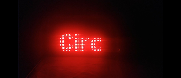
Then, to display a string in the module, select the font using the selectFont() function and print a string message “Welcome to Circuit Digest” in the display using the drawMarquee() function.
   led_module.selectFont(FONT);
   led_module.drawMarquee("Welcome to Circuit Digest",25, (32 * ROW), 0);
Finally, to scroll the text on the LED display board, shift the whole message from Right to Left using a certain time period.
long start = millis();
    long timming = start;
    boolean flag = false;
    while (!flag)
    {
      if ((timming + 20) < millis())
      {
        flag = led_module.stepMarquee(-1, 0);
        timming = millis();
      }
    }
So this is how you can make a Scrolling Text Signboard using Arduino and an LED matrix.
Testing and Troubleshooting
| Problem | Cause | Solution |
| No display output | Power supply issues | Check 5V supply and connections |
| Flickering display | Insufficient current | Upgrade to higher amperage SMPS |
| Incorrect characters | Wrong pin mapping | Verify pinout configuration |
| No scrolling effect | Library issues | Reinstall DMD and TimerOne libraries |
Technical Summary and GitHub Repository
The Technical Summary outlines the core concepts, and the GitHub Repository ensures accessible source code and documentation.


Advanced Applications and Scaling
Professional advertising displays can be built with multiple P10 modules cascaded:
» Horizontal Expansion: Connect modules side-by-side for wider displays
» Vertical Expansion: Stack modules to create taller signage
» Power calculation: Each additional module pulls an additional 20W (4A at 5 volts)
» Control: SPI chain connections allow for multi-module control
Conclusion
One of the best ways to explore LED display technology is with a digital notice board using P10 LED matrix display and Arduino. The P10 LED display with an Arduino is a low-cost alternative for educational or commercial use. The Arduino P10 LED display that utilises the platform is a great springboard for some novel digital signage solutions.
Key Takeaways:
P10 modules offer professional-grade display quality as an Arduino outboard
Proper sizing of the power supply is critical for reliable operation
Modular construction makes it easy to scale up a larger display
IP-rated construction helps with outdoor applications
Flexible programming supports content that changes dramatically
Complete code and demonstration video are given below.
Frequently Asked Questions About the Arduino P10 LED Display
⇥ 1. What power supply is required for the P10 LED display with Arduino?
The single P10 module operation suggests a 5-Volt DC, 3 Amp SMPS power supply. Each module draws about 20 watts, and if you are using more modules in series to make a bigger display, you will have to add up the power requirements.
⇥ 2. Can multiple P10 modules be cascaded to make bigger displays?
Sure, they can! P10 modules are cascadable. Try to connect your modules in an SPI chain. Make sure you change the ROW and COLUMN values in your code, and accordingly, you need to upgrade your power supply too.
⇥ 3. Flickering and wrong characters are displaying. Why?
Flicker is usually caused by the current from your power supply, which is sufficient. Wrong character display is probably due to an incorrect pin connection. Be sure your pinout configuration matches exactly the circuit diagram, and check the power supply specifications.
⇥ 4. What Arduino libraries would I require for programming P10 LEDs?
One must have a DMD library for P10 control operations and a TimerOne library for interrupt operations. To do so, one must visit the official GitHub repositories, download both libraries, and install them within the Arduino IDE.
⇥ 5. How do I change the scrolling text on my P10 display?
In Arduino, one way is to change the string text inside the drawMarquee() function. Alternatively, one can use a serial communication method to dynamically update the text, so you don't have to reflash.
⇥ 6. What is the maximum view distance from the P10 LED display?
The principle is to make the viewing distances in the range of 10-50 m, which suits a P10 display having a pixel pitch of 10 mm. When high brightness (3500-4500 Nits) is provided, it will be visible even under a brighter sun.
Explore LED Project Ideas
This LED has been featured in multiple practical applications;check out the references below to explore them.

Interfacing MAX7219 LED Dot Matrix Display with Arduino
for this project, we will be interfacing Arduino with Dot Matrix Display. We have previously built some attractive projects using this dot matrix display like an Arduino Audio Visualizer, Bluetooth Controlled LED Matrix Display and even an Arduino Snake Game, you can check them out if you are interested.

nterfacing WS2812B Neopixel LED Strip with Arduino
So, in this Arduino inerfacing tutorial series, we are going to look at how to interface such LEDs with Arduino. We will be interfacing the WS2812B LEDs which are also known as NeoPixel. We can build many Neopixel led projects previously, you can check them out if you are interested.

Interfacing WS8211 RGB LED Strip with Arduino: Step by Step Tutorial
In this blog post, we will cover the essential steps involved in setting up the hardware and software for your WS2811 LED strip. We'll explain the necessary connections between the LED strip, Arduino board, and power supply, along with the software libraries required to control the LEDs.
Complete Project Code
#include <SPI.h>
#include <DMD.h>
#include <TimerOne.h>
#include "SystemFont5x7.h"
#include "Arial_black_16.h"
#define ROW 1
#define COLUMN 1
#define FONT Arial_Black_16
DMD led_module(ROW, COLUMN);
void scan_module()
{
  led_module.scanDisplayBySPI();
}
void setup()
{
  Timer1.initialize(2000);
  Timer1.attachInterrupt(scan_module);
  led_module.clearScreen( true );
}
void loop()
{
    led_module.selectFont(FONT);
    led_module.drawMarquee("Welcome to Circuit Digest",25, (32 * ROW), 0);
    long start = millis();
    long timming = start;
    boolean flag = false;
    while (!flag)
    {
      if ((timming + 20) < millis())
      {
        flag = led_module.stepMarquee(-1, 0);
        timming = millis();
      }
    }
  }
Comments
Compiling Error
Hello,
Can I replace the Arduino UNO board with an Arduino Mega board using the same wiring?
Hello! Firslty I want to say thanks a lot for this guide. But I want to use six P10 matrices, 3 x 2 position. Is it possible? (without any new circuit)
Is it possible to replace 'Hello' with 'Modern Church'?" ( Myanmar Sar "ထိန်သစ်ကျောင်း"

Can I make an order of p10smd 16x32 led with Arduino & power supply?