
Consider a fast-moving car, if it suddenly gets hit by another car in opposite direction, the first thing that happens is that, the accelerometer sensor present in the car senses a sudden de-acceleration and triggers an external interrupt to the microcontroller present in the car. Then based on that interrupt the microcontroller produces an electric signal to deploy the airbags immediately. Microcontrollers present in the car monitor many things simultaneously like sensing the speed of the car, checking other sensors, controlling air conditioner temperature etc. So what makes a sudden opening of an airbag in seconds? The answer is interrupts, an interrupt signal is used here which has the highest priority of all.
Another simple example of Interrupts is touch screen mobile phones which have the highest priority to the “Touch” sense. Almost every electronic device has some kind to interrupts to ‘interrupt’ the regular process and do some higher priority things on a particular event. The regular process is resumed after serving the Interrupt.
So technically, Interrupts is a mechanism by which an I/O or instruction can suspend the normal execution of the processor and gets itself serviced like it has higher priority. For example, a processor doing a normal execution can be interrupted by some sensor to execute a particular process that is present in ISR (Interrupt Service Routine). After executing the ISR processor can again resume the normal execution.
Types of Interrupts
There are two types of interrupts:
Hardware Interrupt: It happens when an external event occurs like an external interrupt pin changes its state from LOW to HIGH or HIGH to LOW.
Software Interrupt: It happens according to the instruction from the software. For example Timer interrupts are software interrupt.
You can also check out Arduino Timer Tutorial that we discussed previously.
Interrupts in Arduino
Now we will see how to use interrupts in Arduino Board. It has two types of interrupts:
- External Interrupt
- Pin Change Interrupt
External Interrupt:
These interrupt are interpreted by hardware and are very fast. These interrupts can be set to trigger on the event of RISING or FALLING or LOW levels.
|
Arduino Board |
External Interrupt pins: |
|
UNO , NANO |
2,3 |
|
Mega |
2,3,18,19,20,21 |
Pin Change Interrupts:
Arduinos can have more interrupt pins enabled by using pin change interrupts. In ATmega168/328 based Arduino boards any pins or all the 20 signal pins can be used as interrupt pins. They can also be triggered using RISING or FALLING edges.
Using Interrupts in Arduino
In order to use interrupts in Arduino the following concepts are need to be understood.
Interrupt Service Routine (ISR)
Interrupt Service Routine or an Interrupt handler is an event that has small set of instructions in it. When an external interrupt occurs, the processor first executes these code that is present in ISR and returns back to state where it left the normal execution.
ISR has following syntax in Arduino:
attachInterrupt(digitalPinToInterrupt(pin), ISR, mode);
digitalPinToInterrupt(pin): In Arduino Uno, NANO the pins used for interrupt are 2,3 & in mega 2,3,18,19,20,21. Specify the input pin that is used for external interrupt here.
ISR: It is a function that is called when an external interrupt is done.
Mode: Type of transition to trigger on, e.g. falling, rising, etc.
- RISING: To trigger an interrupt when the pin transits from LOW to HIGH.
- FALLING: To trigger an interrupt when the pin transits from HIGH to LOW.
- CHANGE: To trigger an interrupt when the pin transits from LOW to HIGH or HIGH to LOW (i.e., when the pin state changes ).
Some Conditions while using Interrupt
- Interrupt Service Routine function (ISR) must be as short as possible.
- Delay () function doesn’t work inside ISR and should be avoided.
In this Arduino Interrupt tutorial, a number is incremented from 0 and two push buttons are used to trigger Interrupt, each one is connected to D2 & D3. A LED is used to indicate the Interrupt. If one push button is pressed the led goes ON and display shows interrupt2 and goes off, and when another push button is pressed the led goes OFF and the display shows interrupt1 and goes off.
Components Required
- Arduino Board (In this tutorial Arduino NANO is used)
- Push button - 2
- LED - 1
- Resistor (10K) - 2
- LCD (16x2) - 1
- Bread Board
- Connecting Wires
Circuit Diagram

Circuit Connection between Arduino Nano and 16x2 LCD display:
|
LCD |
Arduino Nano |
|
VSS |
GND |
|
VDD |
+5V |
|
V0 |
To Potentiometer Centre PIN For Controlling Contrast of the LCD |
|
RS |
D7 |
|
RW |
GND |
|
E |
D8 |
|
D4 |
D9 |
|
D5 |
D10 |
|
D6 |
D11 |
|
D7 |
D12 |
|
A |
+5V |
|
K |
GND |
Two push buttons are connected to Arduino Nano at pin D2 & D3. They are used for using two external interrupts, one for turning LED ON and another for turning OFF a LED. Each push button has a pull down resistor of 10k connected to ground. So when push button is pressed it is logic HIGH (1) and when not pressed it is logic LOW (0). A Pull down resistor is compulsory otherwise there will be floating values at the input pin D2 & D3.
A LED is also used to indicate that a Interrupt has been triggered or a button has been pressed.
Arduino Interrupt Programming
In this tutorial a number is incremented from 0 which displays continuously in (16x2) LCD connected to the Arduino Nano, whenever the left push button (interrupt pin D3) is pressed the LED goes ON and display shows Interrupt2, and when the right push button (interrupt pin D2) is pressed the LED goes OFF and display shows Interrupt1.
Complete Code with a working video is given at the end of this tutorial.
1. First the header file for the LCD display is included and then the LCD pins that are used in connecting with the Arduino Nano are defined.
#include<LiquidCrystal.h>
LiquidCrystal lcd (7,8,9,10,11,12); // Define LCD display pins RS, E, D4, D5, D6, D7
2. Inside the void setup () function, first display some intro message on LCD display. Learn more about interfacing LCD with Arduino here.
  lcd.begin(16,2);
  lcd.setCursor(0,0);
  lcd.print("CIRCUIT DIGEST");
  lcd.setCursor(0,1);
  lcd.print("ArduinoInterrupt");
  delay(3000);
  lcd.clear();
3. Then in same void setup () function the input and output pins must be specified. The pin D13 is connected to LED’s Anode, so this pin must be defined as output.
pinMode(13,OUTPUT);
4. Now the main important part in the programing comes that is attachInterrupt() function, it is also included inside the void setup().
attachInterrupt(digitalPinToInterrupt(2),buttonPressed1,RISING);
attachInterrupt(digitalPinToInterrupt(3),buttonPressed2,RISING);
Here it is specified that pin 2 is for external interrupt, and buttonPressed1 function is called when there is RISING (LOW to HIGH) at D2 pin. And pin 3 is also for external interrupt and buttonPressed2 function is called when there is RISING at D3 pin.
5. Inside the void loop(), a number (i) is incremented from zero and printed on LCD(16x2).
 lcd.clear();
 lcd.print("COUNTER:");
 lcd.print(i);
 ++i;
 delay(1000);
In same void loop(), digitalWrite() is used on the pin D13 where LED’s anode is connected. Depending upon the value in variable output LED will turn on or off
digitalWrite(13,output);
6. The most important part is creating a interrupt handler function according to the name that is used in the attachInterrupt() function.
As two interrupt pins are used 2 and 3 so two ISR are required. Here in this programming following ISR are used
buttonPressed1():
void buttonPressed1()
{
   output = LOW;
   lcd.setCursor(0,1);
   lcd.print("Interrupt 1");
}
This function executes when push button on the pin D2 is pressed (RISING EDGE). This function changes the state of the output to LOW causing LED to turn OFF and prints the “interrupt1” on the LCD display.
buttonPressed2():
void buttonPressed2()
{
   output = HIGH;
   lcd.setCursor(0,1);
   lcd.print("Interrupt2");
}
This function executes when push button on the pin D3 is pressed. This function changes the state of the output to HIGH causing LED to turn ON and prints the “interrupt2” on the LCD display.
Arduino Interrupt Demonstration
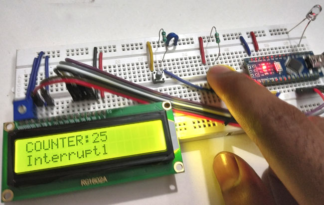
1. When PUSH BUTTON on the leftside is pressed the LED goes ON and the LCD displays Interrupt2.
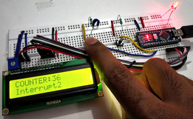
2. When the PUSH BUTTON on the right side is pressed the LED goes OFF and the LCD displays Interrupt1
This is how an Interrupt can be useful to trigger any important task in between of normal execution.
Complete Project Code
//Interrupts using Arduino

//Circuit Digest
#include<LiquidCrystal.h>                        // Including lcd display library

LiquidCrystal lcd (7,8,9,10,11,12);              // Define LCD display pins RS,E,D4,D5,D6,D7

volatile int output = LOW;

int i = 0;
void setup()
{

  lcd.begin(16,2);                              //  setting LCD as 16x2 type

  lcd.setCursor(0,0);

  lcd.print("CIRCUIT DIGEST");

  lcd.setCursor(0,1);

  lcd.print("ArduinoInterrupt");

  delay(3000);

  lcd.clear();

  pinMode(13,OUTPUT);


  attachInterrupt(digitalPinToInterrupt(2),buttonPressed1,RISING);  //  function for creating external interrupts at pin2 on Rising (LOW to HIGH)

  attachInterrupt(digitalPinToInterrupt(3),buttonPressed2,RISING);  //  function for creating external interrupts at pin3 on Rising (LOW to HIGH)


}
void loop()

{

   lcd.clear();

   lcd.print("COUNTER:");

   lcd.print(i);

   ++i;

   delay(1000);

   digitalWrite(13,output);     //Turns LED ON or OFF depending upon output value

}
void buttonPressed1()           //ISR function excutes when push button at pinD2 is pressed

{

   output = LOW;                //Change Output value to LOW

   lcd.setCursor(0,1);

   lcd.print("Interrupt 1");

}
void buttonPressed2()           //ISR function excutes when push button at pinD3 is pressed

{

   output = HIGH;               //Change Output value to HIGH

   lcd.setCursor(0,1);

   lcd.print("Interrupt2");

}
Comments
"In ATmega168/328 based Arduino boards any pins or all the 20 signal pins can be used as interrupt pins".
Could you please explain how?

Good article, but you need to explain how to use software interrupts as well.
Cheers.