
The Arduino Development Platform, at the beginning in 2005, was conceived to be a simple programmable device to be used specifically for art design work. The goal was to create an interface to support the design and use of simple electronics, working with Arduino timer functions without requiring deep programming expertise. This simplicity led to fast adoption by electronic novices and hobbyists across the world, and today, Arduino is used to build Arduino timer projects, develop prototypes, and create proof-of-concept designs.
Although starting with Arduino is fine, you should transition to the core microcontrollers like AVR, ARM, PIC, STM, etc., at some point and program them with their respective applications. This is a good journey to take, because typically, most standard Arduino timer code is reliant on built-in functions like digitalWrite(), analogWrite(), and delay(), never seeing what is going on at a low-level machine language while using Arduino. Instead of following Arduino timer functions, you will be using embedded C programming with Arduino timer interrupts by way of manipulating registers, turning the bits high or low based on your program logic. We will provide a comprehensive guide to Arduino timer functions, register-level programming, and practical Arduino timer counter implementations using Timer1 overflow interrupts. Whether this is your first Arduino UNO timer code or you are moving into complex timing applications, this tutorial will cover everything you need to know, from an overview of some very basic timer concepts to implementing the complete and working circuit with push button controls and an LCD.
In this Arduino timer tutorial, you will learn:
- How to program Arduino timer interrupts using Timer1 registers
- How to write efficient Arduino timer code that doesn't use delay() functions
- Understand Timer/Counter Control Registers (TCCR) and prescaler settings
- How to build practical Arduino timer projects with LED control and an LCD display
- How to create Timer Overflow Interrupt Service Routines (ISR)
- How to calculate preloader values for accurate timing control
Arduino Timer Interrupt System with LED and LCD Control
Build Time: 3-5 hours | Cost: $15-25 | Difficulty: Intermediate
What You'll Learn: Program Timer1 interrupts and configure registers for precise timing.
Applications: Create precision timing systems with interactive LCD displays.
Table of Contents
- What is TIMER in Embedded Electronics?
- Arduino Timer Registers
- Arduino Timer Interrupts
- Components Required
- Circuit Diagram
- Arduino Timer Interrupts vs delay() Function Comparison
- Programming Arduino UNO Timers
- Frequently Asked Questions
- └ Technical Summary and GitHub Repository
- Create Time-Controlled Circuits with Precision and Flexibility
What is TIMER in Embedded Electronics?
An Arduino timer interrupt is a hardware-based timing mechanism that measures precise time intervals. Every microcontroller has a clock oscillator—Arduino Uno operates at 16MHz, determining processing speed. Higher clock frequencies enable faster processing speeds. Arduino timer functions use counters that increment at speeds determined by the clock frequency. In Arduino Uno, each count takes 1/16,000,000 seconds (62 nanoseconds), meaning Arduino executes instructions every 62 nanoseconds when using Arduino timer code. To comprehend what goes on in pre-programmed functions, we need to think about how they work. Take delay() for instance, it sets the timer counter register bits of the ATmega microcontroller used in the Arduino. This Arduino timer tutorial will show you how you can program those timer registers so that you can overcome the limitations of the delay() function.
Timers in Arduino UNO:
In Arduino UNO, there are three timers used for different functions.
Timer0:
It is an 8-bit timer and used in timer functions such as delay(), millis().
Timer1:
It is a 16-bit timer and is used in the servo library.
Timer2:
It is an 8-bit Timer and used in the tone() function.
Arduino Timer Registers
To change the configuration of the timers, the timer registers are used.
1. Timer/Counter Control Registers (TCCRnA/B):
This register holds the main control bits of the timer and is used to control the prescalers of the timer. It also allows control of the mode of the timer using the WGM bits.
Frame Format:
| TCCR1A | 7 | 6 | 5 | 4 | 3 | 2 | 1 | 0 |
| COM1A1 | COM1A0 | COM1B1 | COM1B0 | COM1C1 | COM1C0 | WGM11 | WGM10 |
| TCCR1B | 7 | 6 | 5 | 4 | 3 | 2 | 1 | 0 |
| ICNC1 | ICES1 | - | WGM13 | WGM12 | CS12 | CS11 | CS10 |
Prescaler:
The CS12, CS11, and CS10 bits in TCCR1B set the prescaler value. A prescaler is used to set up the clock speed of the timer. Arduino Uno has prescalers of 1, 8, 64, 256, and 1024.
| CS12 | CS11 | CS10 | USE |
| 0 | 0 | 0 | No Clock Timer STOP |
| 0 | 0 | 1 | CLCK i/o /1 No Prescaling |
| 0 | 1 | 0 | CLK i/o /8 (From Prescaler) |
| 0 | 1 | 1 | CLK i/o /64 (From Prescaler) |
| 1 | 0 | 0 | CLK i/o /256 (From Prescaler) |
| 1 | 0 | 1 | CLK i/o /1024 (From Prescaler) |
| 1 | 1 | 0 | External clock source on T1 Pin. Clock on falling edge |
| 1 | 1 | 1 | External Clock source on T1 pin. Clock on rising edge. |
2. Timer/Counter Register (TCNTn)
This Register is used to control the counter value and to set a preloader value.
Formula for preloader value for required time in seconds:
TCNTn = 65535 – (16x1010xTime in sec / Prescaler Value)
To calculate the preloader value for timer1 for a time of 2 seconds:
TCNT1 = 65535 – (16x1010x2 / 1024) = 34285
Arduino Timer Interrupts
Timer Overflow Interrupt:
Whenever the timer reaches its maximum value, say for example (16-bit-65535), the Timer Overflow Interrupt occurs. So, an ISR interrupt service routine is called when the Timer Overflow Interrupt bit is enabled in the TOIEx present in the timer interrupt mask register TIMSKx.
ISR Format:
ISR(TIMERx_OVF_vect)
{
}
Output Compare Register (OCRnA/B):
Here, when the Output Compare Match Interrupt occurs, then the interrupt service ISR (TIMERx_COMPy_vect) is called and also the OCFxy flag bit will be set in the TIFRx register. This ISR is enabled by setting the enable bit in the OCIExy present in the TIMSKx register. Where TIMSKx is the Timer Interrupt Mask Register.
Timer Input Capture:
Next, when the timer Input Capture Interrupt occurs, then the interrupt service ISR (TIMERx_CAPT_vect) is called and also the ICFx flag bit will be set in TIFRx (Timer Interrupt Flag Register). This ISR is enabled by setting the enable bit in the ICIEx present in the TIMSKx register.
Components Required
- Arduino UNO
- Push Buttons (2)
- LED (Any Color)
- 10k Resistor (2), 2.2k (1)
- 16x2 LCD Display
Circuit Diagram

Circuit Connections between Arduino UNO and 16x2 LCD display:
16x2 LCD | Arduino UNO |
VSS | GND |
VDD | +5V |
V0 | To potentiometer centre pin for contrast control of LCD |
RS | 8 |
RW | GND |
E | 9 |
D4 | 10 |
D5 | 11 |
D6 | 12 |
D7 | 13 |
A | +5V |
K | GND |
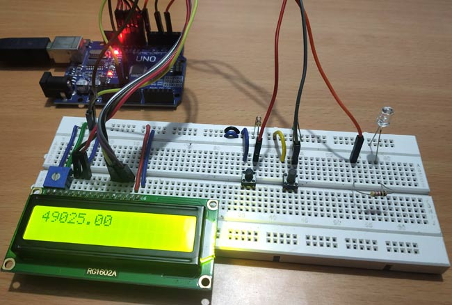
Two Push buttons with pull-down resistors of 10K are connected to the Arduino pins 2 & 4, and an LED is connected to PIN 7 of Arduino through a 2.2K resistor.
The setup will look like the image below.
Arduino Timer Interrupts vs delay() Function Comparison
Why use Arduino timer functions instead of delay()?
| Feature | Using delay() Function | Using Arduino Timer Interrupts | Winner |
|---|---|---|---|
| Code Execution | Blocks all other code | Non-blocking, multitasking | Timer Interrupts |
| Precision | ±4 microsecond accuracy | ±1 microsecond accuracy | Timer Interrupts |
| Multiple Tasks | Does not support multiple timers | Supports multiple timers running at the same time | Timer Interrupts |
| Learning Curve | Very easy to use | Requires knowledge of registers | delay() Function |
| Professional Use | Rarely used in production | Standard practice in industry | Timer Interrupts |
Programming Arduino UNO Timers
This Arduino timer counter demonstrates the Timer Overflow Interrupt implementation to blink LEDs for specific durations. We'll adjust the preloader value (TCNT1) using pushbuttons, creating an interactive Arduino timer counter project. The complete Arduino UNO timer code is provided with detailed explanations. This practical approach teaches Arduino timer interrupt programming through hands-on implementation.
As a 16x2 LCD is used in the project to display the preloader value, so liquid crystal library is used.
#include<LiquidCrystal.h>
The LED anode pin that is connected to Arduino pin 7 is defined as ledPin.
#define ledPin 7
Next, the object for accessing the Liquid Crystal class is declared with the LCD pins (RS, E, D4, D5, D6, D7) that are connected to Arduino UNO.
LiquidCrystal lcd(8,9,10,11,12,13);
Then set the preloader value to 3035 for 4 seconds. Check the formula above to calculate the preloader value.
float value = 3035;
Next in void setup(), first set the LCD in 16x2 mode and display a welcome message for a few seconds.
  lcd.begin(16,2);
  lcd.setCursor(0,0);
  lcd.print("ARDUINO TIMERS");
  delay(2000);
  lcd.clear();
Next, set the LED pin as an OUTPUT pin, and the Push buttons are set as INPUT pins
  pinMode(ledPin, OUTPUT);
  pinMode(2,INPUT);
  pinMode(4,INPUT);
Next, disable all the interrupts:
noInterrupts();
Next the Timer1 is initialised.
TCCR1A = 0;
TCCR1B = 0;
The preloader timer value is set (Initially as 3035).
TCNT1 = value;
Then, the pre-scaler value 1024 is set in the TCCR1B register.
TCCR1B |= (1 << CS10)|(1 << CS12);
The Timer overflow interrupt is enabled in the Timer Interrupt Mask register so that the ISR can be used.
TIMSK1 |= (1 << TOIE1);
At last, all interrupts are enabled.
interrupts();
Now write the ISR for the Timer Overflow Interrupt, which is responsible for turning the LED ON and OFF using digitalWrite. The state changes whenever the timer overflow interrupt occurs.
ISR(TIMER1_OVF_vect)
{
  TCNT1 = value;
  digitalWrite(ledPin, digitalRead(ledPin) ^ 1);
}
In the void loop(), the value of preloader is incremented or decremented by using the push button inputs, and also the value is displayed on a 16x2 LCD.
  if(digitalRead(2) == HIGH)
  {
    value = value+10;             //Incement preload value
  }
  if(digitalRead(4)== HIGH)
  {
    value = value-10;            //Decrement preload value
  }
  lcd.setCursor(0,0);
  lcd.print(value);
}
Frequently Asked Questions
⇥ Which Arduino timer functions should I consider for what applications?
Arduino timer functions are dependent on timer type: the timer0 (8-bit), which uses delay() and millis(), timer1 (16-bit), which is best suited for servo control and long times, and timer2 (8-bit), which uses tone() functions. Many Arduino projects related to LED control would opt for timer1 so a higher level of flexibility and timing accuracy can be accrued; you can simply use timer1 with an overflow interrupt.
⇥ What are some Arduino timer projects that I can do as a beginner?
Some reasonable basic Arduino timer projects would be: LED blink without delay(), clock displays, PWM motor control, delayed sensor data logging, legitimate multi-task scheduling, and real-time data logging, to name a few. If you are just starting, you would want to use just basic LED control using timer1 overflow interrupts, then you can eventually experiment with different timer project applications using LCD displays and push buttons.
⇥ How many timers does the Arduino UNO have, and what are the points of difference?
When you code an Arduino UNO timer, you can utilise three timers: Timer0 (8-bit [0-255]), Timer1 (16-bit [0-65535]), and Timer2. And since timer1 provides the longest duration for most projects and offers the highest level of precision for denoteable timing applications, you can opt for any one of these timers in your projects requiring time-mapping intervals.
⇥ What is the best method for learning about Arduino timer programming?
The best way to approach any Arduino timer tutorial will be to firstly understand timer registers (TCCR, TCNT, TIMSK), practice timer programming by using most lessons with simple LED-based projects, learn about prescaler calculations and using ISR Functions. Build a few hands-on projects and verify them with an oscilloscope, read the relevant datasheet that explains the different registers, and build from the Timer1 basics up to more advanced hands-on projects using multiple timers.
⇥ Why is my Arduino timer interrupt not behaving properly?
Most common sources of error in Arduino timer interrupts come from the following: incorrect prescaler settings, incorrect preloader settings, forgetting to turn on the interrupt enable bit (TIMSK1), interfering libraries using the Timer, and improper ISR syntax. Always disable interrupts during Timer setup with noInterrupts(), make sure to figure out what registers you need to set, and double-check to see if your ISR function uses the same name as the timer vector (TIMER1_OVF_vect) and is defined properly.
Technical Summary and GitHub Repository
This project provides a technical overview of the system architecture, the components and principles of operation. Further details include hardware schematic, software flow and implementation. The source code, as well as support files, can be found on the GitHub repo for collaboration.


So this is how a timer can be used to produce a delay in an Arduino program. Check the video below where we have demonstrated the change in delay by increasing and decreasing the preloader value using Push buttons.
Create Time-Controlled Circuits with Precision and Flexibility
Create a strong foundation in time-based control systems by exploring a range of timer implementations across different platforms.

Timers on Nuvoton N76E003 Microcontroller
In this tutorial we cover how to use the inbuilt Timer of the N76E003 Nuvoton microcontroller and blink an LED using the Timer ESR and Timer Delay.

ESP32 Timers & Timer Interrupts
Timer interrupts allow you to perform a task at very specifically timed intervals, regardless of what else is going on in your code.

Building a Simple Current Detector Circuit with 555 Timer
In this article, we will demonstrate the process of building a simple current detector circuit with 555 Timer and some passive components which can help you to detect open live lines with ease.
Complete Project Code
#include<LiquidCrystal.h>            //LCD display library
#define ledPin 7
LiquidCrystal lcd(8,9,10,11,12,13);
float value = 3035;                   //Preload timer value (3035 for 4 seconds)
void setup()
{
  lcd.begin(16,2);
  lcd.setCursor(0,0);
  lcd.print("ARDUINO TIMERS");
  delay(2000);
  lcd.clear();

  pinMode(ledPin, OUTPUT);
  pinMode(2,INPUT);
  pinMode(4,INPUT);

  noInterrupts();                       // disable all interrupts

  TCCR1A = 0;
  TCCR1B = 0;
  TCNT1 = value;                        // preload timer
  TCCR1B |= (1 << CS10)|(1 << CS12);    // 1024 prescaler
  TIMSK1 |= (1 << TOIE1);               // enable timer overflow interrupt ISR
  interrupts();                         // enable all interrupts
}
ISR(TIMER1_OVF_vect)                    // interrupt service routine for overflow
{
  TCNT1 = value;                                // preload timer
  digitalWrite(ledPin, digitalRead(ledPin) ^ 1);  //Turns LED ON and OFF
}
void loop()
{
  if(digitalRead(2) == HIGH)
  {
    value = value+10;             //Incement preload value
  }
  if(digitalRead(4)== HIGH)
  {
    value = value-10;            //Decrement preload value
  }
  lcd.setCursor(0,0);
  lcd.print(value);
}
Comments
Your code does not work. No matter if you increase or decrease the timer value it always remains at 4 seconds. In your video it is same as I mentioned. Wondering why did you put this code when you can see that it is not working.
I think that expression to have the TCNT1 value is wrong.
TCNT1 = 65535 – (16x106x2 / 1024) = 34285
Arduino has a 16 Mhz clock and not 16Ghz. Also Arduino 3.3V have a 8MHz clock.
superb bro

Arduino: 1.8.11 (Mac OS X), Board: "Arduino Uno"
Sketch uses 3820 bytes (11%) of program storage space. Maximum is 32256 bytes.
Global variables use 77 bytes (3%) of dynamic memory, leaving 1971 bytes for local variables. Maximum is 2048 bytes.
avrdude: ser_open(): can't open device "/dev/cu.usbmodem141401": No such file or directory
Problem uploading to board. See http://www.arduino.cc/en/Guide/Troubleshooting#upload for suggestions.
This report would have more information with
"Show verbose output during compilation"
option enabled in File -> Preferences.