
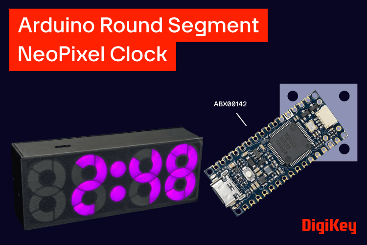
Digital clocks are one of the most popular Arduino projects, and most of them use traditional seven-segment displays to show the time. While these displays are simple and reliable, they usually have the same familiar rectangular shape and monochrome appearance. When I decided to build a new digital clock for my room, I wanted to create something that worked like a seven-segment display but looked completely different.
That led me to design a custom round-shaped seven-segment display using individually addressable WS2812 LEDs. Instead of using a conventional seven-segment module, each segment of the digit is formed using an addressable LED, giving me complete control over its color and brightness. I designed the round segment pattern in Canva and arranged four of these custom digits to create the clock display.
The two key electronic components behind this project are the WS2812 addressable LEDs used to create the custom display segments and the Arduino Nano R4, which acts as the main controller for the clock. Both were available through DigiKey.in, which made it easy to source the important components and move from the initial idea to building the actual hardware. The result is a colourful Round Segment NeoPixel Clock that displays the current time and temperature while automatically changing the display color every minute.
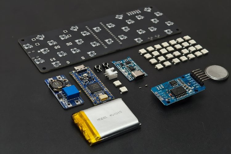
Required Components
- Arduino Nano R4
- RTC Module
- 30 × WS2812 NeoPixel LEDs
- 2 × Push Buttons
- ON/OFF Switch
- 3.7V Li-ion Battery
- Charging Module
- Boost Converter Module
- 2-pin connector with wires
- Header Pins
Step 1: Designing the Round Segment Display
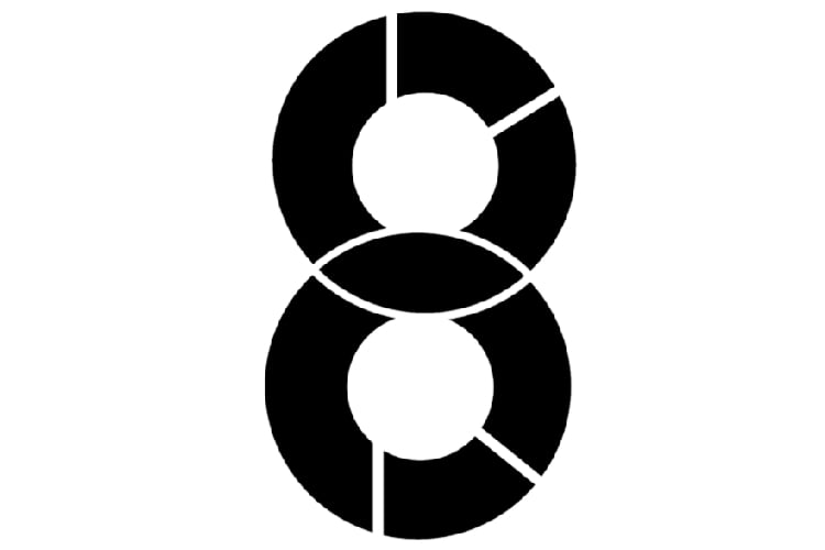
Before starting the electronics design, I first focused on the display itself. A traditional seven-segment display consists of seven individual segments arranged in a figure-eight pattern. By turning different segments ON and OFF, we can display digits from 0 to 9. Instead of following the traditional rectangular segment layout, I designed a custom round-shaped seven-segment digit using Canva. The goal was to create a display that looks modern and unique while still maintaining the functionality of a seven-segment display.
Each digit contains seven curved segments arranged in a circular pattern. Every segment is represented by NeoPixel LEDs, allowing complete control over colors and brightness. Unlike standard seven-segment displays, this design can display millions of colors and create beautiful lighting effects.
Step 2: Selecting the Controller
To control the clock, I chose the Arduino Nano R4.
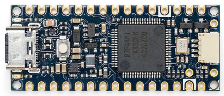
The Arduino Nano R4 is compact, powerful, and provides enough GPIO pins for the project. It also offers excellent performance for controlling multiple NeoPixel LEDs while simultaneously communicating with the RTC module.
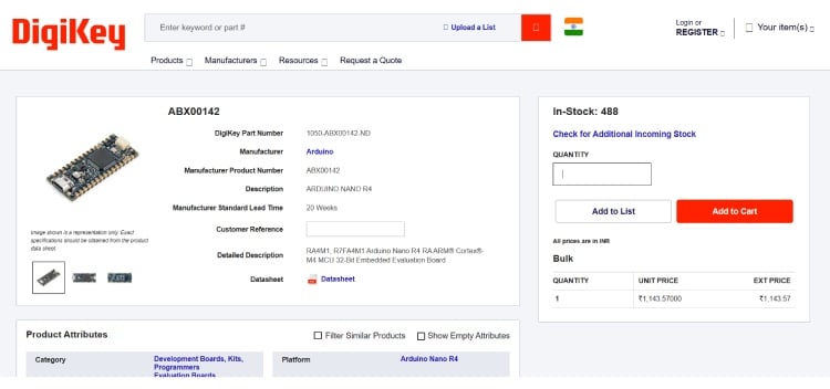
For this project, the Arduino Nano R4 was sourced through DigiKey. The board's compact form factor makes it well suited for our custom PCB, while providing the GPIO and processing capability required to control the NeoPixel display and communicate with the RTC.
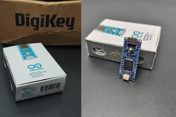
The Arduino Nano R4 and other DigiKey-available components used in this project are linked in the components section above for easy reference. Ordering components from DigiKey was straightforward. I simply added the required components to my cart, entered the shipping details, and placed the order. Within a week, the package arrived safely packed and ready to use.
Step 3: How the Clock Works
The operation of the clock is very simple. The DS3231 Real-Time Clock module continuously keeps track of the current time and date, even when the main power is disconnected. It uses a backup battery to maintain accurate timekeeping. The Arduino Nano R4 communicates with the DS3231 through the I²C interface and reads the current time. Using this information, the Arduino determines which segments should be illuminated and updates the NeoPixel LEDs accordingly. The DS3231 module also contains a built-in temperature sensor, allowing the clock to display room temperature. One of the main features of this clock is its automatic color-changing effect. Every minute, the Arduino generates a new color and applies it to the displayed digits, giving the clock a vibrant and dynamic appearance. Two push buttons are provided for adjusting the time whenever required.
Step 4: Circuit Diagram

The circuit consists of three main sections:
Control Section
The Arduino Nano R4 acts as the main controller and handles all operations including:
- Reading time from the RTC module
- Driving the NeoPixel LEDs
- Reading button inputs
- Displaying temperature
Timekeeping Section
The DS3231 RTC module is connected to the Arduino using the I²C interface.
SDA → Arduino SDA
SCL → Arduino SCL
The RTC module provides accurate time and temperature information.
Display Section
The display consists of 30 WS2812 NeoPixel LEDs arranged to form four round-segment digits. All NeoPixel LEDs are connected in a serial chain, allowing them to be controlled using a single data pin from the Arduino.
User Interface
Two push buttons are connected to the Arduino and are used to:
Increase hours
Increase minutes
These buttons make time adjustment quick and easy.
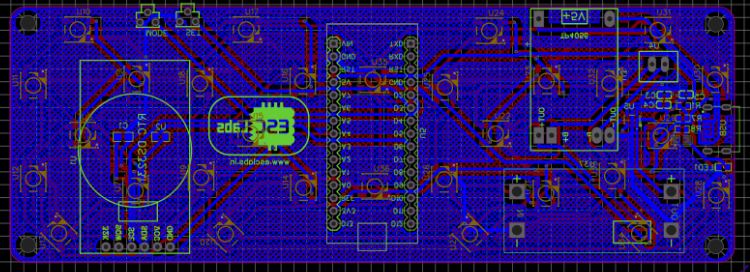
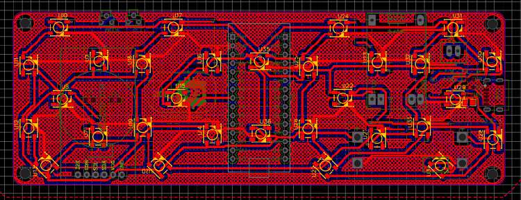
Step 5: PCB Design
To simplify the assembly process, I designed a custom PCB using EasyEDA.
Instead of manually wiring thirty NeoPixel LEDs and other components, the PCB provides a neat and reliable solution.
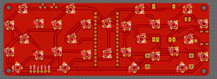
The front side of the PCB contains the NeoPixel LEDs arranged according to the round-segment digit design.
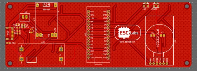
The back side houses:
- Arduino Nano R4
- RTC Module
- Push Buttons
- Power Circuitry
- Connectors
After completing the PCB layout, I generated the Gerber files required for fabrication.
Step 6: PCB Fabrication
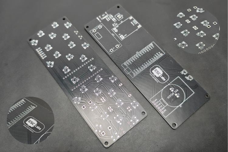
Once the PCB design was finalized, I sent the Gerber files for fabrication.
A few days later, the manufactured PCBs arrived.
The PCB quality was excellent, with clean silkscreen printing, precise drilling, and high-quality solder masks.
The custom PCB significantly reduced wiring complexity and made assembly much easier.
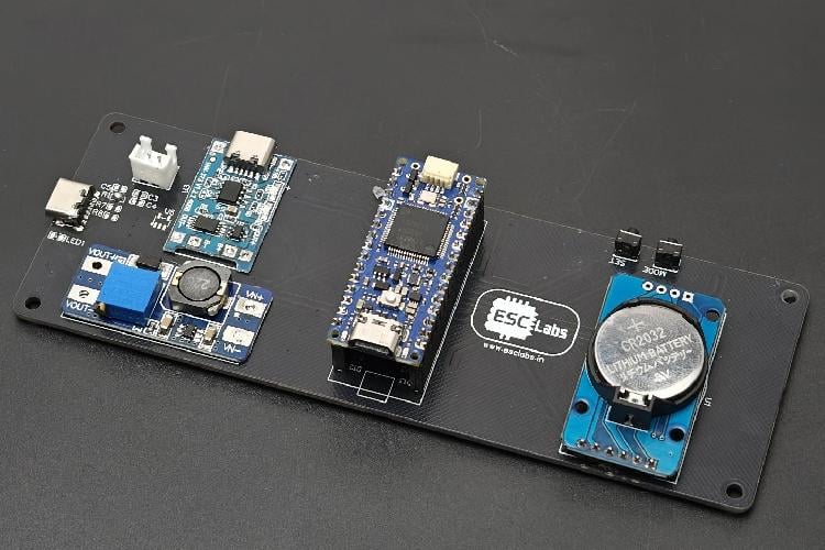
Step 7: PCB Assembly
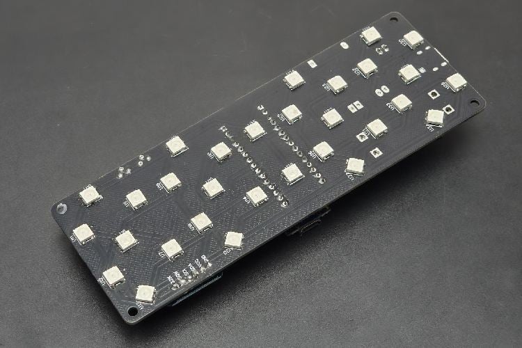
Assembly began with soldering the NeoPixel LEDs. Since the clock uses thirty WS2812 LEDs, careful alignment was necessary to ensure all segments displayed correctly.
After completing the LED installation, I first soldered the female headers for Arduino Nano R4, followed by soldering the remaining components:
- Header pins
- Push buttons
- Connectors
- Power components
After inspecting all solder joints and verifying the connections, the electronics assembly was complete.
The finished PCB looked clean and professional.
Step 8: Designing the Enclosure
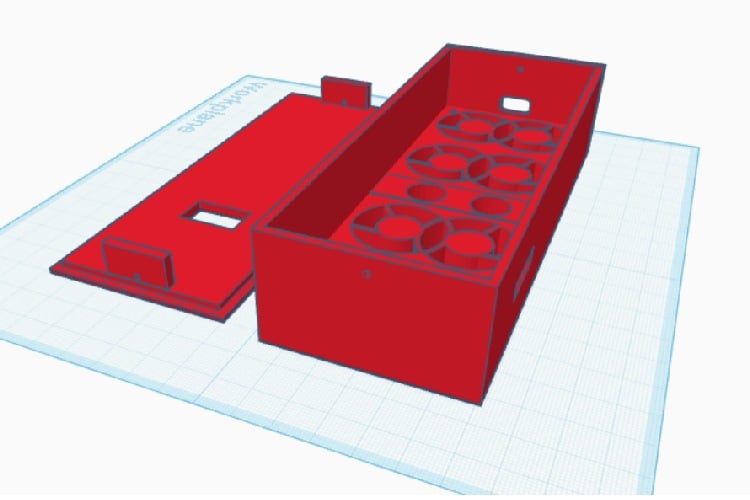
With the electronics completed, the next step was designing an enclosure. I designed the enclosure using Tinkercad. The enclosure was created specifically to match the shape and dimensions of the custom PCB.
The design consists of:
- Front diffuser section
- Main body
- Rear cover
- Mounting points for buttons and electronics
The enclosure protects the electronics while giving the clock a clean and professional appearance.
Step 9: 3D Printing the Enclosure
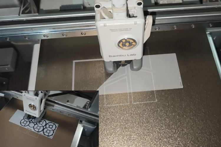
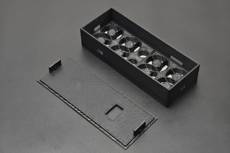
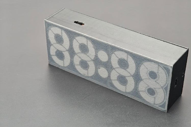
The enclosure was printed using a Bambu Lab A1 3D printer. To create an integrated diffuser, I used a dual-color printing technique. The first few layers were printed using white filament. These layers act as a diffuser and help spread the NeoPixel light evenly across each segment. The remaining layers were printed using black filament, creating a strong enclosure while improving display contrast. This combination produces bright and uniform illumination while preventing unwanted light leakage.
Step 10: Programming the Arduino
The software for the clock was developed using the Arduino IDE.
The code uses:
- TimeLib library
- DS3232RTC library
- FastLED library
(DS3232RTC is an Arduino library that supports the Maxim Integrated DS3231 and DS3232 Real-Time Clocks.)
The Arduino continuously reads the current time from the DS3231 RTC module and updates the display accordingly.
Additional features implemented in the software include:
- Automatic color changes every minute
- Temperature display mode
- Time adjustment using buttons
- Smooth NeoPixel control
After compiling and uploading the code to the Arduino Nano R4, the clock was ready for testing.
#include <DS3232RTC.h>
#include <TimeLib.h>
#include <Wire.h>
#include <FastLED.h>
These are the libraries used fo our clock
#define NUM_LEDS 30
#define COLOR_ORDER RGB  // Define color order for your strip
#define LED_PIN 6 // Data pin for led comunication
#define DST_PIN 5  // Define DST adjust button pin
#define MIN_PIN 3  // Define Minutes adjust button pin
#define HUR_PIN 2  // Define Hours adjust button pin
#define BRI_PIN 4 // Define Light sensor pin
The code allocates 30 LEDs in total. The structural architecture assumes four digits, each using 7 segments (28 LEDs), plus 2 additional LEDs dedicated to the blinking central colon (dots).
The Seven-Segment Matrix and Color Palette
An addressable LED strip is fundamentally a linear array. To convert this line of light into readable numbers, the code utilizes a multi-dimensional array called a lookup table:
RGB leds[NUM_LEDS];
byte digits[12][7] = {
 {1,0,1,1,1,1,1},
 {1,0,1,0,0,0,0},
 {0,1,1,1,0,1,1},
 {1,1,1,1,0,0,1},
 {1,1,1,0,1,0,0},
 {1,1,0,1,1,0,1},
 {1,1,0,1,1,1,1},
 {1,0,1,1,0,0,0},
 {1,1,1,1,1,1,1},
 {1,1,1,1,1,0,0},
 {0,0,0,1,1,1,1},
 {0,1,1,1,1,0,0}};
Each row corresponds to a symbol (0–9, plus custom characters for temperature metrics). The seven elements in each row represent the individual segments of a digit (commonly labeled A through G). A 1 signals that the segment should receive power, while a 0 keeps it dark.
To keep the display visually engaging, the code initializes an array of 21 hex-color constants (ColorTable). Rather than rendering a static color, the program introduces a dynamic feature: every time the minute updates, it randomly selects a new hue from this palette.
Initialization and Environmental Awareness
The setup() function establishes the initial state of the micro-controller:
void setup(){
 Serial.begin(9600);
 Wire.begin();
 myRTC.begin();
 FastLED.addLeds<WS2812B, LED_PIN, COLOR_ORDER>(leds, NUM_LEDS);
 FastLED.setBrightness(75); // Set initial brightness
 pinMode(DST_PIN, INPUT_PULLUP); // Define DST adjust button pin
 pinMode(MIN_PIN, INPUT_PULLUP); // Define Minutes adjust button pin
 pinMode(HUR_PIN, INPUT_PULLUP); // Define Hours adjust button pin
 pinMode(BRI_PIN, INPUT_PULLUP); // Define bright adjust
 TempShow = false; // do not show temperature
}
The buttons are declared using INPUT_PULLUP, utilizing internal resistors to hold the pins at a HIGH logic state until a physical press drives them to ground (LOW).
Time Capture and Array Transformation
The engine of the clock relies on pulling data from the hardware clock and transforming it into indexable LED commands.
GetTime()
This function queries the RTC module, handles a 24-hour to 12-hour conversion math rule, and applies a Daylight Savings Time (DST) offset if the DST boolean flag is active. It compresses the current time into a single four-digit integer (e.g., 04:15 PM becomes 415). Simultaneously, it creates a rhythmic blinking colon by evaluating whether the current second is odd or even.
TimeToArray()
Once GetTime() returns the integer, TimeToArray() acts as the painter. It extracts each digit one by one using modulo and division math (Now % 10 and Now /= 10). It maps these digits against the digits[12][7] lookup table to turn the appropriate LEDs on or off.
if (digit != last_digit)
     {
       cylon();
       ledColor =  ColorTable[random(21)];
     }
     last_d
The Transition Effect: This block checks if the minute digit has changed. If a change is detected, it triggers a custom cylon() animation—a fluid, rainbow-colored wave that sweeps back and forth across the entire strip—before locking in the new time and a fresh color.
The Secondary Function: Thermometer Mode
At a precise interval-specifically the 27th second of every minute-the code temporarily hijacks the clock display via TempToArray().
It extracts the internal temperature of the RTC chip, converts it to a standard Celsius scale, and displays it. The function includes logic to handle sub-zero temperatures by explicitly mapping out a negative sign (lighting up only segment G of the leading digit) and utilizes leading-zero blanking to ensure the final temperature reads naturally on the screen.
Real-Time Interactivity and the Core Executive Loop
While managing the displays, the Arduino actively checks for manual configurations through DSTcheck() and TimeAdjust(). If you press the hardware buttons, the code catches the pulse, increments the internal hour or minute configuration, and immediately flashes that new data back to the permanent EEPROM memory of the RTC hardware chip.
The loop() Lifecycle
The main execution cycle functions as a continuous feedback loop:
void loop()  // Main loop
{
 BrightnessCheck(); // Check brightness
 DSTcheck(); // Check DST
 TimeAdjust(); // Check to se if time is geting modified
 TimeToArray(); // Get leds array with required configuration
 TempToArray();
 FastLED.show(); // Display leds array
 if (TempShow == true)
 delay (8000);
}
Step 11: Final Assembly
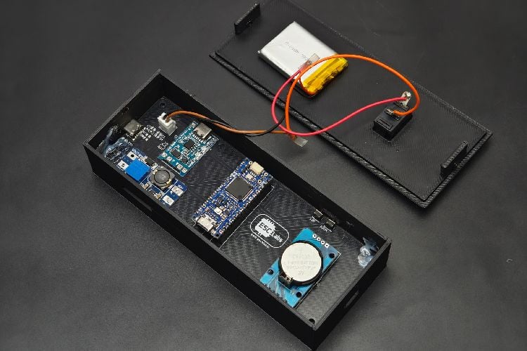
After programming the Arduino, all components were installed into the enclosure. The PCB was secured in place, the buttons were aligned with the enclosure openings, and all wiring was carefully arranged. Once everything was fitted correctly, the rear cover was attached, completing the assembly process. The Round Segment Clock was now fully assembled and ready for use.
Step 12: Testing the Round Segment Clock
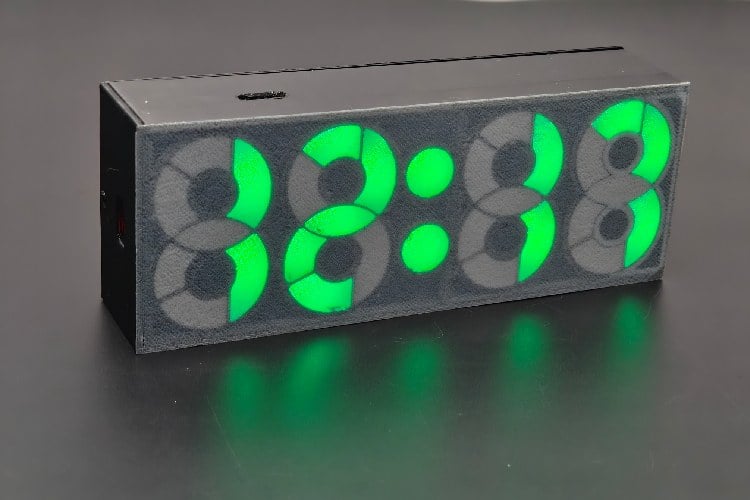
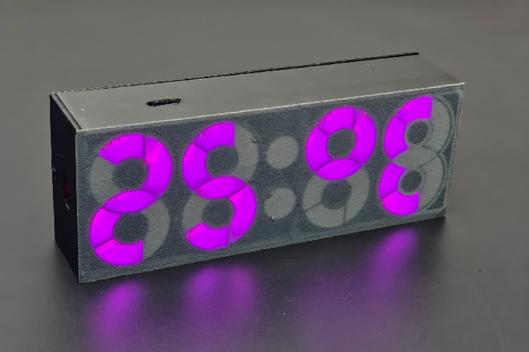
After powering up the clock, everything worked as expected. The clock accurately displays the current time using the custom round-segment digits. The display is bright, colorful, and easy to read. Using the two push buttons, the time can be adjusted whenever necessary. The built-in temperature sensor of the DS3231 module allows the clock to display room temperature, adding extra functionality. The most attractive feature of the clock is its automatic color-changing effect. Every minute, the digits change to a new color, giving the clock a vibrant and dynamic appearance.
This project demonstrates how a traditional seven-segment display concept can be transformed into something unique and modern using NeoPixel LEDs and custom design techniques. By combining an Arduino Nano R4, a DS3231 RTC module, custom PCB design, and a 3D-printed enclosure, I created a colorful Round Segment Clock that not only displays time accurately but also serves as an eye-catching decorative piece.
This repository provides the complete source code; the link is provided below.


Complete Project Code
//EDISON SCIENCE CORNER
//EDISON SCIENCE CORNER
#include <DS3232RTC.h>
#include <TimeLib.h>
#include <Wire.h>
#include <FastLED.h>
DS3232RTC myRTC(false);
#define NUM_LEDS 30
#define COLOR_ORDER RGB  // Define color order for your strip
#define LED_PIN 6 // Data pin for led comunication
#define DST_PIN 5  // Define DST adjust button pin
#define MIN_PIN 3  // Define Minutes adjust button pin
#define HUR_PIN 2  // Define Hours adjust button pin
#define BRI_PIN 4 // Define Light sensor pin
CRGB leds[NUM_LEDS];
byte digits[12][7] = {
 {1,0,1,1,1,1,1},
 {1,0,1,0,0,0,0},
 {0,1,1,1,0,1,1},
 {1,1,1,1,0,0,1},
 {1,1,1,0,1,0,0},
 {1,1,0,1,1,0,1},
 {1,1,0,1,1,1,1},
 {1,0,1,1,0,0,0},
 {1,1,1,1,1,1,1},
 {1,1,1,1,1,0,0},
 {0,0,0,1,1,1,1},
 {0,1,1,1,1,0,0}};


bool Dot = true;  //Dot state
bool DST = true; //DST state// false to true
bool TempShow = false;
int last_digit = 0;
// int ledColor = 0x0000FF; // Color used (in hex)
long ledColor = CRGB::DarkOrchid; // Color used (in hex)
//long ledColor = CRGB::MediumVioletRed;
//Random colors i picked up
long ColorTable[21] = {
 CRGB::Amethyst,  //white
 CRGB::Aqua,    //pink
 CRGB::Blue,     //Blue
 CRGB::Chartreuse,// Gold
 CRGB::DarkGreen, //Red
 CRGB::DarkMagenta,//Aqua
 CRGB::DarkOrange,  // yellow green
 CRGB::DeepPink,  //Aqua
 CRGB::Fuchsia,  //Sea blue
 CRGB::Gold,    //Gold
 CRGB::GreenYellow,//off white
 CRGB::LightCoral,//white
 CRGB::Tomato,//white
 CRGB::Salmon,//Pure white
 CRGB::Red,// Drak Green
 CRGB::Orchid,//blue white
 CRGB::Sienna,//yellow white
 CRGB::Purple,// aqua
 CRGB::DarkOrange,//yellow green
 CRGB::FloralWhite,//white
 CRGB::Yellow  //yellow
};

void setup(){
 Serial.begin(9600);
 Wire.begin();
 myRTC.begin();
 FastLED.addLeds<WS2812B, LED_PIN, COLOR_ORDER>(leds, NUM_LEDS);
 FastLED.setBrightness(75); // Set initial brightness
 pinMode(DST_PIN, INPUT_PULLUP); // Define DST adjust button pin
 pinMode(MIN_PIN, INPUT_PULLUP); // Define Minutes adjust button pin
 pinMode(HUR_PIN, INPUT_PULLUP); // Define Hours adjust button pin
 pinMode(BRI_PIN, INPUT_PULLUP); // Define bright adjust
 TempShow = false; // do not show temperature
}
// Get time in a single number, if hours will be a single digit then time will be displayed 155 instead of 0155
int GetTime(){
 tmElements_t Now;
 myRTC.read(Now);
 int hour=Now.Hour;
 int minute=Now.Minute;
 int second =Now.Second;
 if (second % 2==0)
  {Dot = false;}
   else {Dot = true;};

 // Apply DST adjust before 12-hour conversion
 if (DST){
   hour = (hour + 1) % 24;
 };
 if (hour >= 12) {
   hour -= 12;
 }
 if (hour == 0) {
   hour = 12;
 }
 return (hour*100+minute);
};
// Check Light sensor and set brightness accordingly
void BrightnessCheck(){
 const byte sensorPin = BRI_PIN; // light sensor pin
 const byte brightnessLow = 20; // Low brightness value
 const byte brightnessHigh = 75; // High brightness value
 int sensorValue = digitalRead(sensorPin); // Read sensor
 if (sensorValue == 0) {FastLED.setBrightness(brightnessHigh);}
 else {FastLED.setBrightness(brightnessLow);}
 };
// Convert time to array needed for display
void TimeToArray(){
 int Now = GetTime();  // Get time

 int cursor = 30; // last led number

 // Serial.print("Time is: ");Serial.println(Now);
 // DST is now handled in GetTime()
 if (Dot){leds[28]=ledColor;
          leds[29]=ledColor;}
  else  {leds[28]=0x000000;
          leds[29]=0x000000;
   };

 for(int i=1;i<=4;i++){
   int digit = Now % 10; // get last digit in time
   if (i==1){
   //  Serial.print("Digit 4 is : ");Serial.print(digit);Serial.print(" ");
     cursor = 21;

     for(int k=0; k<=6;k++){
       // Serial.print(digits[digit][k]);
       if (digits[digit][k]== 1){leds[cursor]=ledColor;}
        else if (digits[digit][k]==0){leds[cursor]=0x000000;};
        cursor ++;
       };
     // Serial.println();
     if (digit != last_digit)
     {
       cylon();
       ledColor =  ColorTable[random(21)];
     }
     last_digit = digit;

     }
   else if (i==2){
     // Serial.print("Digit 3 is : ");Serial.print(digit);Serial.print(" ");
     cursor =14;

     for(int k=0; k<=6;k++){
       // Serial.print(digits[digit][k]);
       if (digits[digit][k]== 1){leds[cursor]=ledColor;}
        else if (digits[digit][k]==0){leds[cursor]=0x000000;};
        cursor ++;
       };
     // Serial.println();
     }
    else if (i==3){
     // Serial.print("Digit 2 is : ");Serial.print(digit);Serial.print(" ");
     cursor =7;
     for(int k=0; k<=6;k++){
       // Serial.print(digits[digit][k]);
       if (digits[digit][k]== 1){leds[cursor]=ledColor;}
        else if (digits[digit][k]==0){leds[cursor]=0x000000;};
        cursor ++;
       };
     // Serial.println();
     }
   else if (i==4){
     // Serial.print("Digit 1 is : ");Serial.print(digit);Serial.print(" ");
     cursor =0;
     if(digit !=0){
        for(int k=0; k<=6;k++){
       // Serial.print(digits[digit][k]);
       if (digits[digit][k]== 1){leds[cursor]=ledColor;}
        else if (digits[digit][k]==0){leds[cursor]=0x000000;};
        cursor ++;
       };
     }
     if(digit ==0){
     for(int k=0; k<7;k++){
       leds[k]=0x000000;
       };

     // Serial.println();
     }
   }
    Now /= 10;
 };
};
// Convert temp to array needed for display
void TempToArray(){
 tmElements_t tm;
 myRTC.read(tm);
 if (tm.Second != 27) {
   TempShow = false;
   return;
 }
 TempShow = true;
 int t = myRTC.temperature();
 int celsius = t * 25; // Equivalent to (t / 4.0) * 100 using integer math
 bool isNegative = (celsius < 0);
 celsius = abs(celsius);
 Serial.print("Temp is: ");Serial.println(celsius);

 int cursor = 30; // last led number

 leds[28]=0x000000;
 leds[29]=0x000000;

 for(int i=1;i<=4;i++){
   int digit = celsius % 10; // get last digit in temp
   if (i==1){
     Serial.print("Digit 4 is : ");Serial.print(digit);Serial.print(" ");
     cursor = 21;

     for(int k=0; k<=6;k++){
       Serial.print(digits[10][k]);
       if (digits[10][k]== 1){leds[cursor]=ledColor;}
        else if (digits[10][k]==0){leds[cursor]=0x000000;};
        cursor ++;
       };
     Serial.println();
   }
   else if (i==2){
     Serial.print("Digit 3 is : ");Serial.print(digit);Serial.print(" ");
     cursor =14;

     for(int k=0; k<=6;k++){
       Serial.print(digits[11][k]);
       if (digits[11][k]== 1){leds[cursor]=ledColor;}
        else if (digits[11][k]==0){leds[cursor]=0x000000;};
        cursor ++;
       };
     Serial.println();
     }
   else if (i==3){
     Serial.print("Digit 2 is : ");Serial.print(digit);Serial.print(" ");
     cursor =7;
     for(int k=0; k<=6;k++){
       Serial.print(digits[digit][k]);
       if (digits[digit][k]== 1){leds[cursor]=ledColor;}
        else if (digits[digit][k]==0){leds[cursor]=0x000000;};
        cursor ++;
       };
     Serial.println();
     }
   else if (i==4){
     Serial.print("Digit 1 is : ");Serial.print(digit);Serial.print(" ");
     cursor =0;
     if (isNegative) {
       // Display minus sign (only segment G / index 1 is ON)
       for(int k=0; k<=6; k++){
         if (k == 1) { leds[cursor] = ledColor; }
         else { leds[cursor] = 0x000000; }
         cursor++;
       }
     } else {
       // Normal leading zero blanking
       if(digit != 0){
         for(int k=0; k<=6;k++){
           if (digits[digit][k]== 1){leds[cursor]=ledColor;}
            else if (digits[digit][k]==0){leds[cursor]=0x000000;};
            cursor ++;
           };
       }
       else if(digit ==0){
         for(int k=0; k<7;k++){
           leds[k]=0x000000;
         };
         Serial.println();
       }
     }
   }
   celsius /= 10;
 };
};

void DSTcheck(){
  int buttonDST = digitalRead(DST_PIN);
  // Serial.print("DST is: ");Serial.println(DST);
  if (buttonDST == LOW){
   if (DST){
     DST=false;
     // Serial.print("Switching DST to: ");Serial.println(DST);
     }
     else if (!DST){
       DST=true;
       // Serial.print("Switching DST to: ");Serial.println(DST);
     };
  delay(500);
  };
 }
void TimeAdjust(){
 int buttonH = digitalRead(HUR_PIN);
 int buttonM = digitalRead(MIN_PIN);
 if (buttonH == LOW || buttonM == LOW){
   delay(500);
   tmElements_t Now;
   myRTC.read(Now);
   int hour=Now.Hour;
   int minutes=Now.Minute;
   int second =Now.Second;
     if (buttonH == LOW){
       if (Now.Hour== 23){Now.Hour=0;}
         else {Now.Hour += 1;};
       }else {
         if (Now.Minute== 59){Now.Minute=0;}
         else {Now.Minute += 1;};
        // if (Now.Hour > 12){Now.Hour = Now.Hour -12;}  // 24 to 12 hr
        // else {Now.Hour = Now.Hour ;};
         };
   myRTC.write(Now);
   }
 }
/* coool effect function*/
void fadeall() { for(int i = 0; i < NUM_LEDS; i++) { leds[i].nscale8(250); } }

void cylon () {
 static uint8_t hue = 0;
 Serial.print("x");
 // First slide the led in one direction
 for(int i = 0; i < NUM_LEDS; i++) {
   // Set the i'th led to red
   leds[i] = CHSV(hue++, 255, 255);
   // Show the leds
   FastLED.show();
   // now that we've shown the leds, reset the i'th led to black
   // leds[i] = CRGB::Black;
   fadeall();
   // Wait a little bit before we loop around and do it again
   delay(10);
 }
 Serial.print("x");
 // Now go in the other direction.
 for(int i = (NUM_LEDS)-1; i >= 0; i--) {
   // Set the i'th led to red
   leds[i] = CHSV(hue++, 255, 255);
   // Show the leds
   FastLED.show();
   // now that we've shown the leds, reset the i'th led to black
   // leds[i] = CRGB::Black;
   fadeall();
   // Wait a little bit before we loop around and do it again
   delay(10);
 }
}

void loop()  // Main loop
{
 BrightnessCheck(); // Check brightness
 DSTcheck(); // Check DST
 TimeAdjust(); // Check to se if time is geting modified
 TimeToArray(); // Get leds array with required configuration
 TempToArray();
 FastLED.show(); // Display leds array
 if (TempShow == true)
 delay (8000);

}