

In our household, most of the appliances are powered from the AC supply such as Lights, TVs, and Fans, etc. We can turn ON/OFF them digitally if needed, using Arduino and Relays by building a Home automation setup. But what if we need to control the power of those devices for example to dim the AC Lamp or to Control the speed of the Fan. In that case, we have to use phase control technique and static switches like TRIAC to control the phase of AC supply voltage.
So in this tutorial, we will learn about an AC lamp dimmer using Arduino and TRIAC. Here a TRIAC is used to switch the AC lamp, as this is a Power electronic fast switching device which is the best suited for these applications. Let’s follow the complete article for the hardware details and programming of this project. Also, check our previous tutorials on Light Dimming:
- IR Remote Controlled TRIAC Dimmer Circuit
- Arduino Based LED Dimmer using PWM
- 1 Watt LED Dimmer Circuit
- Power LED Dimmer using ATmega32 Microcontroller
Components Used:
- Arduino UNO-1
- MCT2E optocoupler -1
- MOC3021 optocoupler -1
- BT136 TRIAC-1
- (12-0)V, 500mA Step down transformer-1
- 1K,10K, 330ohm Resistors
- 10K Potentiometer
- AC Holder with Lamp
- AC wires
- Jumpers
Before going further we will learn about Zero crossing, TRIAC, and optocoupler.
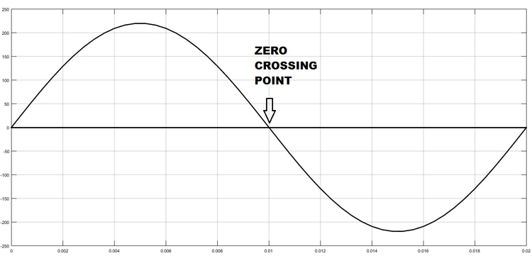
Zero Crossing Detection Technique
To control the AC voltage, the first thing we have to do is, to detect the zero crossing of the AC signal. In India, the frequency of AC signal is 50 HZ and as it is alternating in nature. Hence, every time the signal comes to Zero point, we have to detect that point and after that trigger the TRIAC as per the power requirement. The Zero crossing point of an AC signal is shown below:
TRIAC Working
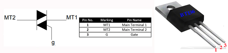
TRIAC is a three-terminal AC switch which can be triggered by a low energy signal at its gate terminal. In SCRs, it conducts in only one direction, but in the case of TRIAC the power can be controlled at both directions. Here we are using a BT136 TRIAC for AC Lamp dimming purpose.
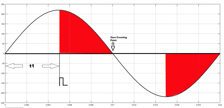
As shown in the figure above, the TRIAC is triggered at a firing angle of 90 degrees by applying a small gate pulse signal to it. The time “t1” is the delay time which we have to give as per our dimming requirement. For example, in this case as the firing angle is 90 percent, hence the power output will also be halved and hence the lamp will also glow with half intensity.
We know that the frequency of AC signal is 50 Hz here. So the time period will be 1/f, which will be 20ms., so for a half cycle, this will be 10ms or 10,000 microseconds. Hence for controlling the power of our AC lamp, the range of “t1” can be varied from 0-10000 microseconds. Learn more about Triac and its working here.
Optocoupler
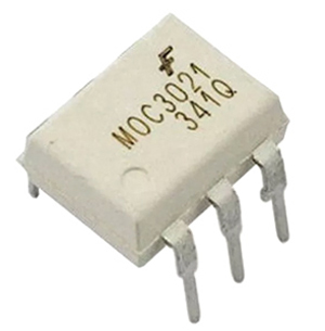
Optocoupler is also known as Optoisolator. It is used to maintain isolation between two electrical circuits like DC and AC signals. Basically, it consists of an LED that emits infrared light and the photosensor which detects it. Here we are used a MOC3021 optocoupler to control the AC lamp from microcontroller signals which is a DC signal. We previously used the same MOC3021 optocoupler in TRIAC dimmer circuit. Also learn more about Optocouplers and its types by following the link.
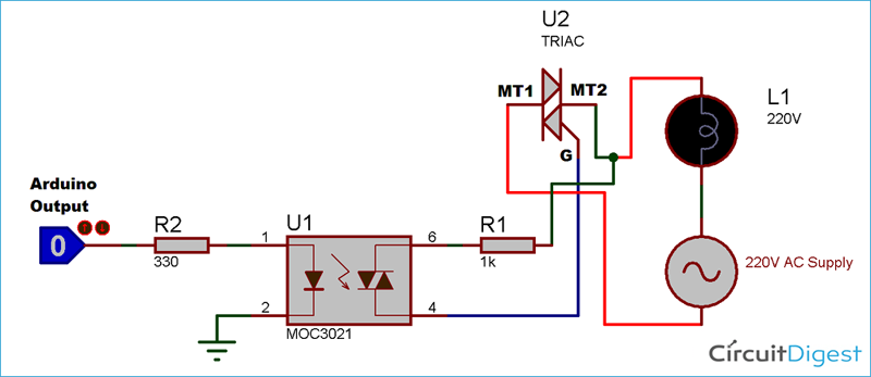
Circuit Diagram:
Circuit diagram for AC Light Dimmer is given below:

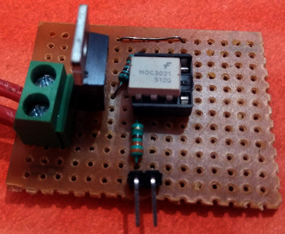
TRIAC and Optocoupler Connection Diagram:
I have soldered a circuit of TRIAC and Optocoupler MOC3021 on a perf board. After soldering it will look like below:
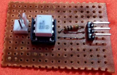
I have also soldered optocoupler MCT2E on perf board for connecting it to Transformer for AC supply:
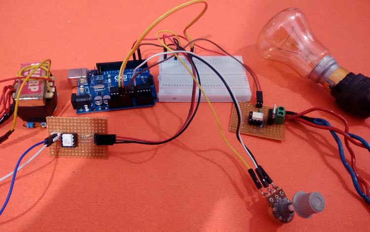
And the complete circuit for Arduino Lamp Dimmer will look like below:
Programming Arduino for AC Light Dimmer:
After successful completion of hardware setup, now its time to program the Arduino. The complete program with a demo video is given at the end. Here we have explained the code stepwise for better understating.
In the first step, declare all the global variables, which are going to use throughout the code. Here the TRIAC is connected to pin 4 of Arduino. Then the dim_val is declared to store the value of the dimming step which we will use in the program.
int LAMP = 4;
int dim_val=0;
Next, inside setup function declare the LAMP pin as output and next configure an interrupt to detect the zero crossing. Here we have used a function called attachInterrupt, which will configure digital Pin 2 of Arduino as external interrupt and it will call the function named zero_cross, when it detects any interrupts at its pin.
void setup()
{
  pinMode(LAMP, OUTPUT);
  attachInterrupt(digitalPinToInterrupt(2), zero_cross, CHANGE);
}
Inside infinite loop, read the analog value from potentiometer which is connected at A0. Then map it to a value range of (10-49). To find out this we have to do a small calculation. Earlier I have told that, each half cycle is equivalent to 10,000 microseconds. So, let we need to control the dimming in 50 steps (which is an arbitrary value. You can also change it). I have taken the minimum step as 10, not Zero, because 0-9 steps give approximately the same power output and it is not recommended practically to take the maximum step number. So, I have taken the maximum step as 49.
Then each step time can be calculated as 10000/50= 200 microseconds. This will be used in the next part of the code.
void loop()
{
    int data=analogRead(A0);
    int data1 = map(data, 0, 1023,10,49);
    dim_val=data1;
}
In the final step, configure the interrupt-driven function zero_cross. Here the dimming time can be calculated by multiplying the individual step time with no. of steps. Then after this delay time, the TRIAC can be triggered using a small high pulse of 10 microseconds which is sufficient to turning on a TRIAC.
void zero_cross()
{
  int dimming_time = (200*dim_val);
  delayMicroseconds(dimming_time);
  digitalWrite(LAMP, HIGH);
  delayMicroseconds(10);
  digitalWrite(LAMP, LOW);
}
Working of Arduino Lamp Dimmer Circuit
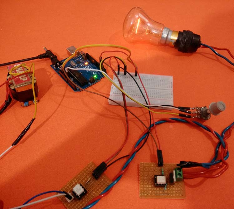
Below are the pictures of showing three stages of dimming the AC bulb using Arduino and TRIAC.
1. Low dimming step
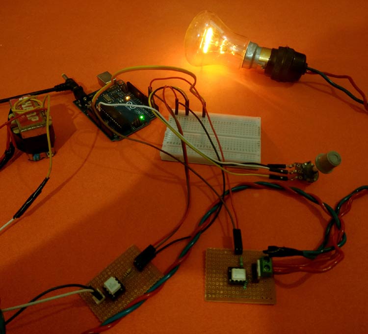
2. Medium Dimming step
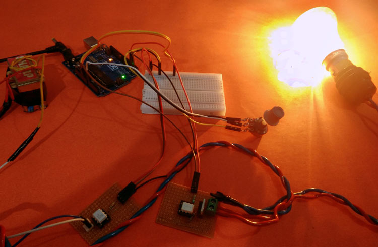
3. Maximum Dimming step:
This is how an AC Light Dimmer circuit can be built easily using TRIAC and optocoupler. A Working Video and Arduino Light Dimmer Code is given below
Complete Project Code
int LAMP = 4;
int dim_val=0;
void setup()
{
  pinMode(LAMP, OUTPUT);
  attachInterrupt(digitalPinToInterrupt(2), zero_cross, CHANGE);
}
void zero_cross()
{
  int dimming_time = (200*dim_val);
  delayMicroseconds(dimming_time);
  digitalWrite(LAMP, HIGH);
  delayMicroseconds(10);
  digitalWrite(LAMP, LOW);
}

void loop()
{
    int data=analogRead(A0);
    int data1 = map(data, 0, 1023,10,49);
    dim_val=data1;
}

Hello,
Firstly many thanks for this really great project. I am very interested in using arduino in AC circuits. The explanations are great, but there is only one thing that I didn't understand, and that iss related to the usage of the other optocoupler (MCT2E).
1. On of its sides is 12V ac, and on the other is 5V (minus the voltage drop on the 330ohm resistor). How it's supposed to sense when the voltage on 12V passed through the zero?
2. How do we know that zero crossing on 12V ac and on 230V ac ocurrs ath the same time? 12V ac is obtained through 230/12V transformer, and is it possible that may exist some phase shift, resulting in different zero crossing moments?
Thank you very much!
Ljiljan Maksimovic