

LED bulbs are said to be 80% more efficient than other conventional lighting options like fluorescent and incandescent bulbs. The fast adaption of LED bulbs is already noticeable around us and the global LED bulb market value has reached to around $5.4 Billion in 2018. A challenge, in designing these LED bulbs is that LED light, as we know works on DC voltage and the mains power supply is AC, hence we need to design a LED Driver circuit that could convert the AC mains voltage into suitable level of DC voltage required for the LED bulb. In this article we will design such a practical low cost LED driver circuit using LNK302 Switching IC to power four LEDs (in series) which can provide 200 Lumens operating at 13.6V and consuming around 100-150mA.
Warning: Before we move any further it is very important to make sure that you work with extreme caution around AC mains. The circuit and details provided here was tested and handled by experts. Any mishaps can lead to serious damages and might also be lethal. Work at your own risk. You have been warned.
Transformerless Power Supply circuit
A very crude LED driver circuit can be build using the Capacitor Dropper method, just like we did in our previous Transformerless power supply project. While these circuits are still being used in some very cheap electronic products it suffers from a lot of drawback which we will discuss later. Hence in this tutorial we will not be using the Capacitor Dropper method, instead build a reliable LED driver circuit using a switching IC.
Drawback of Capacitor Drop Transfromerless Power Supply Circuit
This type of transformerless power supply circuit is cheaper than standard switch-mode power supply due to the low component count and the absence of magnetics (transformer). It uses a capacitor dropper circuit that uses the reactance of a capacitor to drop the input voltage.
Although this type of transformerless designs proves very useful in certain cases where the production cost of a particular product has to be lower, the design does not provide Galvanic Isolation from AC mains and hence should only be used in products that do not come in direct contact with humans. For example, it can be used in high power led lights, where the enclosure is made with hard plastic, and no circuit part is exposed for user's interaction once installed. The problem with these types of circuits is that if the power supply unit fails, it could reflect the high input AC voltage across the output and that can become a death trap.
Another drawback is that these circuits are limited to low current rating. This is because the output current depends on the value of capacitor used, for higher current rating a very large capacitor has to be used. This is a problem because bulky capacitors also increase the board space and increase production cost. Also, the circuit has no protection circuit, like output short circuit protection, over current protection, thermal protection, etc. If they need to be added, it also increases cost and complexity. Even if all are done well, they are not reliable.
So, the question is, is there any solution that can be cheaper, efficient, simple, and smaller in size along with all protection circuits to make a non-isolated AC to DC high power LED driver circuit? The answer is yes and that is exactly what we are going to build in this tutorial.
Selecting the right LED for your LED bulb
The first step in designing an LED bulb driver circuit is deciding on the load i.e the LED that we are going to use in our bulbs. The ones that we use in this project are shown below.
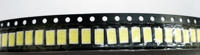
The LEDs in the above strip is a 5730 packages 0.5 watt cool white LEDs with a luminous flux of 57lm. The forward voltage is 3.2V minimum to the 3.6V maximum with a forward current of 120 to 150 mA. Therefore, to produce 200 lumens of light, 4 LEDs can be used in series. The required voltage of this strip will be 3.4 x 4 = 13.6V and the current 100-120mA will flow through each leds.
Here is the schematic of LEDs in series –

LNK304 - LED Driver IC
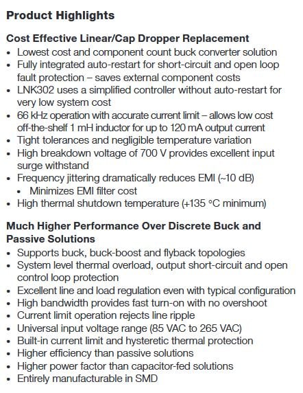
The driver IC selected for this application is LNK304. It can successfully provide the required load for this application along with auto restart, short-circuit, and thermal protection. The features can be seen in the below image –
Selecting the other components
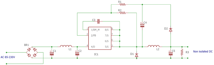
The selection of other components depends on the driver IC selected. In our case the datasheet, reference design uses a half-wave rectifier using two standard recovery diodes. But in this application, we used Diode Bridge for full-wave rectification. It may increase the production cost, but in the end, the design tradeoffs also matter for proper power delivering across the load. The schematic diagram without values can be seen in the below image, now let’s discuss how to select the values
So, the Diode Bridge BR1 is selected DB107 for this application. However, 500mA Diode Bridge can also be selected for this application. After the diode bridge, a pi filter is used where two electrolytic capacitors are required along with an inductor. This will rectify the DC and also reduce the EMI. The capacitors values selected for this application is a 10uF 400V electrolytic capacitors. The values need to be higher than the 2.2uF 400V. For cost optimization purposes, 4.7uF to 6.8uF can be the best choice.
For the inductor, more than 560uH is recommended with 1.5A of the current rating. Therefore, C1 and C2 are selected to be 10uF 400V and L1 as 680uH and a 1.5A DB107 diode bridge for DB1.
The rectified DC is fed into the driver IC LNK304. The bypass pin needs to be connected with the source by a 0.1uF 50V capacitor. Therefore C3 is 0.1uF 50V ceramic capacitor. D1 is needed to be an ultrafast diode with a reverse recovery time 75 ns. It is selected as UF4007.
FB is the feedback pin and the resistor R1 and R2 are used for determining the output voltage. The reference voltage across the FB pin is 1.635V, the IC switches the output voltage till it obtains this reference voltage on its feedback pin. Therefore, by using a simple voltage divider calculator, the resistors value can be selected. So, for getting 13.6V as output, the resistor value is selected based on the below formula
Vout = (Source voltage x R2) / (R1 + R2)
In our case Vout is 1.635V, the Source voltage is 13.6V. We selected the R2 value as 2.05k. So, the R1 is 15k. Alternatively you can use this formula to also calculate the source voltage. The capacitor C4 is selected as 10uF 50V. D2 is a standard rectifier diode 1N4007. The L2 is the same as L1 but the current can be less. L2 is also 680uH with 1.5A rating.
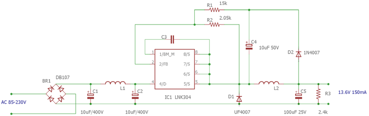
The output filter capacitor C5 is selected as 100uF 25V. R3 is a minimum load which is used for regulation purposes. For zero load regulation, the value is selected as 2.4k. The updated schematic along with all values is shown below.

Working of Transformerless LED Driver Circuit
The complete circuit is working in MDCM (Mostly Discontinuous Conduction Mode) Inductor switching Topology. The AC to DC conversion is made by the diode bridge and the pi filter. After getting the rectified DC, the power processing stage is done by the LNK304 and D1, L2 and C5. The voltage drop across the D1 and D2 is almost the same, the capacitor C3 checks the output voltage and depending on the voltage across the capacitor C3 is sensed by the LNK304 using the voltage divider and regulating the switching output across the source pins.
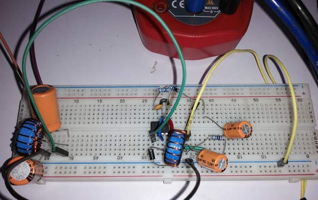
Building the LED Driver Circuit
All the components required for the constructing the circuit, except for inductors. Hence we have to wind our own Inductor using enameled copper wire. Now there is a mathematical approach to calculate the type of core, thickness of wire, number of turns etc. But for simplicity purpose we will just make some turns with the available bobbin and copper wire and use an LCR meter to check if we have reached the required value. Sine our project is not very sensitive to inductor value and current rating is low, this crude way will work just fine. If you do not have a LCR meter you can also use an oscilloscope to measure the value of Inductor using the resonant frequency method.
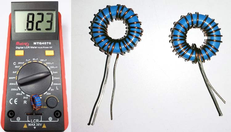
The above image shows that the Inductors are checked and the value is more than the 800uH. It is used for L1 and L2. A simple copper clad board is also made for LEDs. The circuit is constructed in a breadboard.
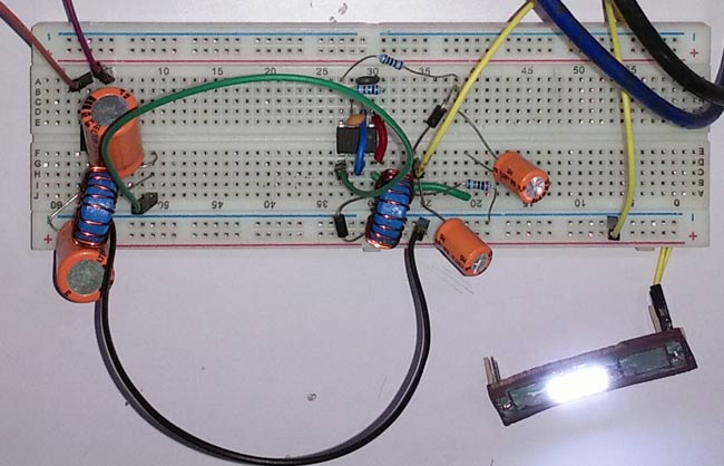
Testing the LED driver Circuit
The circuit is first tested using a VARIAC (Variable Transformer) and then checked in universal input voltage that is 110V/220V AC voltage. The multimeter on the left is connected across the AC input and another multimeter on the right is connected across a single LED to check the output DC voltage.
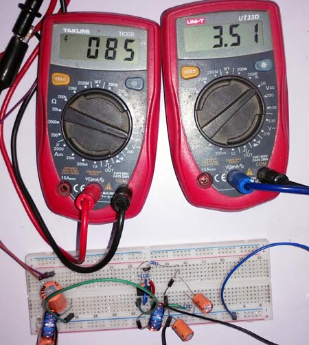
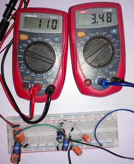
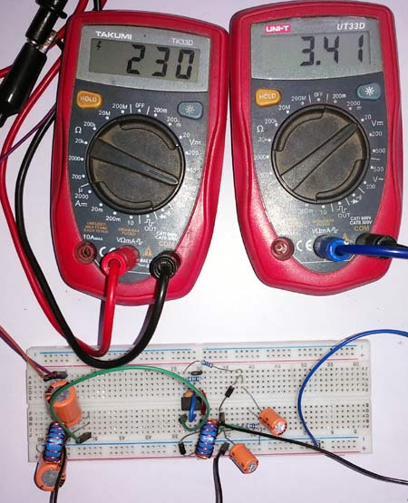
The reading is taken in three different input voltages. The first one in the left side showing an input voltage of 85VAC and across a single led it is showing 3.51V whereas the led voltage across different input voltage is slightly changing. The in detail working video can be found below.
hello sir how can I get…
hello sir how can I get 300mA and 30V out put , out of this driver circuit?
I want it for 9 of series 1w full spectrum LEDs

Hi Sir.
I built this circuit but I have a problem that I need to connect leds as parallel. So I have 2.8v leds and I used 470ohms for each but resistors that I used became connected parallel with RL (2.4K ohms) and therefore lnk304 fb is dropping consistendly. Correspondingly 12V output voltages is dropping until leds flash off. When I connect the leds serial there is no problem. But in paralllel leds light about 1 min and flash out after voltage drop. How can I solve this problem?
Thank you.