

The most used electronics components in any electronic design are Resistors (R), Capacitors (C), and the Inductors (L). Most of us are familiar with the basics of these three passive components and how to use them. Theoretically (under ideal conditions) a capacitor can be considered as a pure capacitor with only capacitive properties, but in practice a capacitor will also have some resistive and inductive properties coupled with it, which we call as the parasitic resistance or parasitic inductance. Yes, just like a parasite this unwanted resistance and inductance properties sits inside a capacitor preventing it from behaving like a pure capacitor.
Hence while designing a circuit engineers primarily consider the ideal form of the component, in this case capacitance and then along with it the parasitic components (Inductance and resistance) is also considered to be in series with it. This parasitic resistance is termed as the Equivalent Series Resistance (ESR) and the parasitic inductance is termed as Equivalent series Inductance (ESL) The value of this inductance and resistance will be very small, that it can be neglected in simple designs. But in some high power or high frequency application these value can be very crucial and if not considered might reduce the component efficiency or output unexpected results.
In this article we will learn more about this ESR and ESL, how to measure them and how they can affect a circuit. Similar to this an Inductor will also have some parasitic properties associated with it called DCR which we will discuss in another article some other time.
ESR in Capacitors
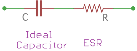
An ideal capacitor in series with resistance is called Equivalent series resistance of the capacitor. The equivalent series resistance or ESR in a capacitor is the internal resistance that appears in series with the capacitance of the device.
Let's see the below symbols, which are representing ESR of the capacitor. The capacitor symbol is representing the ideal capacitor and the resistor as an equivalent series resistance. The resistor is connected in series with the capacitor.
An ideal capacitor is lossless, meaning the capacitor store charge and delivers the same amount of charge as output. But in the real world, capacitors have a small value of finite internal resistance. This resistance comes from the dielectric material, leakage in an insulator or in the separator. Adding to this, Equivalent series resistance or ESR will have different values in different types of capacitors based on its capacitance value and construction. Hence we have to measure the value of this ESR practically to analyze the complete characteristics of a capacitor.
Measuring ESR in Capacitors
Measuring the ESR of a capacitor is bit tricky because the resistance is not a pure DC resistance. This is due to the property of capacitors. Capacitors block DC and pass the AC. Therefore, standard ohms meter cannot be used to measure the ESR. There are specific ESR meters that are available in the market which can be useful to measure the ESR of a capacitor. These meters use Alternating current, such as square wave in a specific frequency across the capacitor. Based on the change in frequency of the signal the ESR value of the capacitor can be calculated. An advantage with this method is that, since the ESR is measured directly across the two terminals of a capacitor it can be measured without de-soldering it from the circuit board.
Another theoretical way to calculate ESR of the capacitor is to measure the Ripple voltage and Ripple current of the capacitor and then the ratio of both will give the value of ESR in the capacitor. However, a more common ESR measurement model is to apply alternating current source across the capacitor with an additional resistance. A crude circuit to measure ESR is shown below
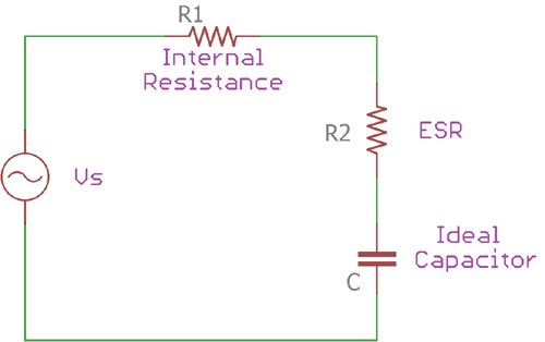
The Vs is the sine wave source and R1 is the internal resistance. The capacitor C is the Ideal capacitor whereas the R2 is the Equivalent Series Resistance of the ideal capacitor C. One thing needs to be remembered is that in this ESR measurement model, the capacitor’s lead inductance is ignored and it is not considered as a part of the circuit.
The transfer function of this circuit can be depicted in the below formula-
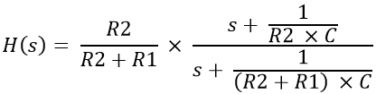
In the above equation, the high pass feature of the circuit is reflected; the approximation of the transfer function can further be evaluated as –
H(s) ≈ R2 / (R2 + R1) ≈ R2 / R1
The above approximation is suitable for high-frequency operations. At this point, the circuit starts to attenuate and act as an attenuator.
The attenuation factor can be expressed as –
⍺ = R2 / (R2 + R1)
This attenuation factor and the sine wave generator’s internal resistance R1 can be used to measure the capacitors ESR.
R2 = ⍺ x R1
Therefore, a function generator can be useful to calculate the ESR of the capacitors.
Normally, ESR value ranges from a few milliohms to several ohms. Aluminum electrolytic and tantalum capacitors have high ESR compared with the box type or ceramic capacitors. However, modern advancement in capacitor manufacturing technology makes it possible to manufacture super low ESR capacitors.
How ESR affects the Performance of Capacitor
ESR value of the capacitor is a crucial factor for capacitor output. High ESR capacitor dissipates heat in high current application and the capacitor life decrease eventually, which also contributes to the malfunction in electronics circuits. In power supplies, where high current is a concern, the low ESR capacitors are required for filtration purposes.
Not only in power supply related operations but low ESR value, is also essential for the high-speed circuit. In very high operating frequencies, typically ranging from hundreds of MHz to several GHz, ESR of the capacitor plays a vital role in power delivery factors.
ESL in capacitor
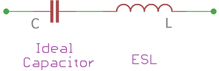
Same as like ESR, ESL is also a crucial factor for capacitors. As discussed before, in real situation capacitors are not ideal. There is a stray resistance as well as stray inductance. A typical ESL model of capacitor shown below. The capacitor C is the ideal capacitor and the inductor L is the series inductance connected in series with the ideal capacitor.
Normally, ESL is highly dependable on the current loop; increase in current loop also increases the ESL in capacitors. The distance between the lead termination and circuit connecting point (including pads or tracks) also influences the ESL in capacitors because increased termination distance also increases the current loop resulting in high Equivalent series inductance.
Measuring ESL of a capacitor
The measurement of ESL can be done easily by observing the impedance versus frequency plot given by the capacitor manufacturer’s datasheet. The impedance of the capacitor changes when the frequency across the capacitor is changed. During the situation, when at in a specific frequency the capacitive reactance and the inductive reactance are equal, it is called as the ‘knee point’.
At this point, the capacitor self resonates. The ESR of the capacitor contributes to flatten out the impedance plot till capacitor reached the ‘knee’ spot or at the self-resonating frequency. After the knee point, the capacitor impedance starts to increase due to the ESL of the capacitor.
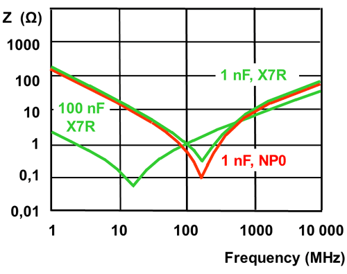
The above image is an Impedance vs Frequency plot of a MLCC (Multi layer ceramic capacitor). Three capacitors, 100nF, 1nF X7R class and 1nF of NP0 class capacitors are shown. The ‘knee’ spots can easily be identified across the lower point of V shaped plot.
Once the knee point frequency is identified, the ESL can be measured by the below formula
Frequency = 1 / (2π√(ESL x C))
How ESL affects the Capacitor Output
The capacitors output degrades by increased ESL, same as like ESR. Increased ESL contributes to the unwanted flow of current and generates EMI, which further creates malfunctions in high-frequency applications. In power supply related system, parasitic inductance contributes to the high ripple voltage. Ripple voltage is proportional to the ESL value of the capacitors. Large ESL value of capacitor can also induce ringing waveforms, making the circuit to behave odd.
Practical importance of ESR and ESL
The below image provides the actual model of ESR and ESL in capacitor.
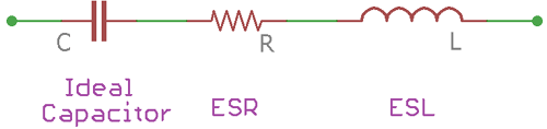
Here, the Capacitor C is an ideal capacitor, the resistor R is Equivalent Series Resistance and the inductor L is the Equivalent Series Inductance. Combining these three the real capacitor is made.
ESR and ESL are not so pleasant characteristics of a capacitor, which cause a variety of performance reduction in electronic circuits, especially in high frequency and high current applications. High ESR value contributes to the poor performance due to the power losses caused by ESR; the power loss can be calculated using Power law I2R where R is the ESR value. Not only this, noises and high voltage drop also occur due to high ESR value as per the Ohms law. Modern capacitor manufacturing technology reduces the ESR and ESL value of the capacitor. A huge improvement can be seen in today’s SMD versions of multilayer capacitors.
Lower ESR and ESL value capacitors are preferred as output filters in switching power supply circuits or SMPS designs because the switching frequency is high in these cases, typically close to several MHz ranging from hundreds of kHz. Because of this the input capacitor and the output filter capacitors need to be in low ESR value so that the Low-frequency ripples has no effects in the overall performance of the power supply unit. The ESL of the capacitors also needs to be low, so that the impedance of the capacitor does not interact with the power supply switching frequency.
In a low noise power supply, where the noises need to be suppressed and the output filter stages should be low in numbers, high quality super low ESR and low ESL capacitors are useful for smooth output and stable power delivery to the Load. In such an application, polymer electrolytes are a suitable choice and commonly preferred over Aluminum Electrolytic capacitors.
