

The inductor is one of the major passive components in electronics. The basic passive components in electronics are resistors, capacitors and inductors. Inductors are closely related to the capacitors as they both use an electric field to store energy and both are two terminal passive components. But capacitors and Inductors have different construction properties, limitations and usage.
Inductor is a two terminal component which stores energy in its magnetic fields. It is also referred as coil or choke. It blocks any changes in current flowing through it.
The inductor is characterized by the value of inductance which is the ratio of voltage (EMF) and current change inside the coil. The unit of inductance is Henry. If the current flow through an inductor is changed at the rate of one ampere per second and 1V of EMF is produced inside the coil, then the value of inductance will be 1 Henry.
In Electronics the inductor with a value of Henry is rarely used as it is a very high value in terms of the application. Typically, much lower values like, Milli Henry, Micro Henry or Nano Henry are used in most of the applications.
| Symbol | Value | Relation with Henry |
| mH | Milli Henry | 1/1000 |
| uH | Micro Henry | 1/1000000 |
| nH | Nano Henry | 1/1000000000 |
The symbol of an inductor is shown in the below image-

The symbol is a representation of twisted wires which means wires are constructed to become a coil.
Construction of Inductor
Inductors are formed using insulated copper wires which further formed as a coil. The coil can be different in shapes & sizes and also can be wrapped in a different type of materials.
The inductance of an Inductor is highly dependable on multiple factors, such as number of turns of wire, the spacing between the turns, no of layers of turns, type of core materials, its magnetic permeability, size, shape etc.


There is a huge difference between Ideal Inductor and the actual real inductors used in electronic circuitry. Real inductor not only has inductance, but it also has capacitance and resistance. The closely wrapped coils produce a measurable amount of stray capacitance between coil turns. This additional capacitance, as well as wire resistance, alters the high-frequency behaviors of an inductor.
Inductors are used in almost every electronic product, some DIY applications of inductor are:
How does an Inductor work?
Before discussing further, it is important to understand the difference between two terminologies, Magnetic Field and Magnetic Flux.
During the Current flow through the conductor, a magnetic field is generated. These two things are linearly proportional. Therefore, if the current is increased, so the magnetic field will also increase. This magnetic field is measured in the SI unit, Tesla (T). Now, what is Magnetic Flux? Well, it is the measurement or quantity of the magnetic field which passes through a specified area. Magnetic Flux also has a unit in SI standard, it is Weber.
So, as of now, there is a magnetic field across inductors, produced by the current flowing through it.
To understand further, understanding of Faraday’s law of inductance is required. As per Faraday’s law of inductance, the generated EMF is proportional to the rate of change of the magnetic flux.
VL = N (dΦ / dt)
Where N is the number of turns and Φ is the amount of flux.
Construction of an Inductor
One generic, standard inductor construction and working can be demonstrated as a copper wire wrapped tightly across a core material. In the below image, copper wire is closely wrapped across a core material, making it a two terminal passive inductor.
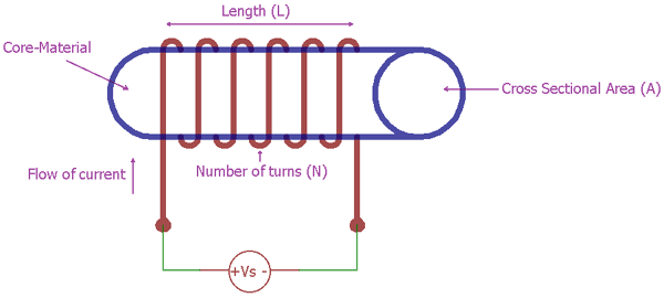
When the current flow through the wire, the electromagnetic field will develop across the conductor and electromotive force or EMF will generate depending upon the rate of change of the magnetic flux. So, the flux linkage will be Nɸ.
The inductance of wound coil inductor in a core material is said to be
µN2A / L
where N is the number of turns
A is the cross sectional area of the core material
L is the length of the coil
µ is the permeability of the core material which is a constant.
The formula of back EMF generated is
Vemf(L) = -L (di / dt)
where di/dt is the rate of current change
L is the self-inductance.
The induced EMF direction will be opposite of the applied current source.
There are readily available inductance meter in market to measure the inductance of a coil but it can be also built with few components. Here are two DIY Inductance meter:
- LC Meter using Arduino: Measuring Inductance and Frequency
- How to measure value of Inductor or Capacitor using Oscilloscope – Resonant Frequency Method
Why an Inductor blocks AC rather than DC?
It is quite interesting. To understand this, one needs to understand the Lenz law. As per the Lenz law, the direction of current induced in a conductor due to the change in magnetic field is such that it creates a magnetic field that opposes the change that produced it.
So, there are two types of applications. First is to apply DC across the inductor and the other one is to apply AC across the inductor.
When the alternating current is applied across the inductor, the AC changes the current flow which is opposed by the inductor by increasing the reactance. The higher the frequency of AC, the higher the rate of change current and the higher the blocking effect from the inductor.
But, at the time DC is applied through the inductor, the inductor act as a near short circuit with very low resistance. In a steady state DC flow, the rate of current changes is zero which further make the di/dt zero. So, there was no voltage is induced and the Inductor do not oppose the flow of DC.
What will happen when we apply DC switching across an inductor?
Let's considered the below circuit.
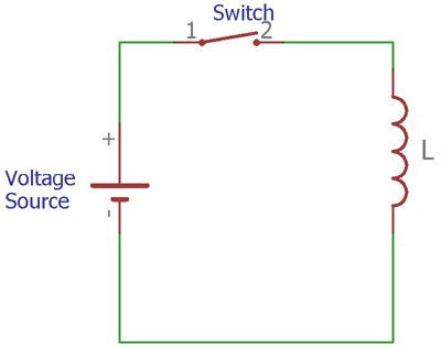
In the circuit, if a voltage source is applied to the inductor using a switch. This switch can be anything like transistors, MOSFET or any kind of typical switch which will provide the voltage source to the inductor.
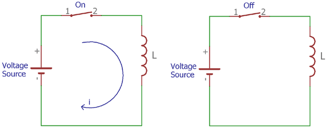
There are two States of the circuitry.
When the switch is open, no current flow will occur in the inductor as well as the rate of current change is zero. So, the EMF is also zero.
When the switch is closed the current from the voltage source to the inductor start rising until the current flow reaches the maximum steady state value. In this time the current flow through the inductor increases and the rate of current change depends on the value of inductance. As per Faraday's law, the inductor generates back EMF which stays until the DC gets into the stable state. During the steady state there is no current change in the coil and current simply pass through the coil.
During this time, an ideal inductor will act as a short circuit as it has no resistance, but in a practical situation, the current flow through the coil and the coil has a resistance as well as the capacitance.
On the other state when switch is being closed again, the Inductor current goes down rapidly and again there is change is current which further leads to EMF generation.
Current and Voltage in an Inductor
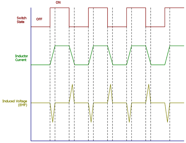
The above graph is showing the Switch state, Inductor Current and Induced Voltage in the time constant.
Power through the inductor can be calculated using Ohms power law where P = Voltage x Current. Therefore, in such a case, the voltage is –L (di / dt) and the current is i. So, the power in an Inductor can be calculated using this formula
PL = L (di / dt) i
But during the steady state the real Inductor is just act like a resistor. So the power can be calculated as
P = V2R
It is also possible to calculate the stored energy in an Inductor. An Inductor stores energy using the magnetic field. The energy stored in the Inductor can be calculated using this formula-
W(t) = Li2(t) / 2
There are different types of Inductors available in terms of their construction and size. Construction wise Inductors can be formed in air core, ferrite core, iron core etc and Shape-wise there are different types of Inductors available, like the drum core type, choke type, transformer type etc.
Applications of Inductors
Inductors are used in a wide area of application.
- In RF related application.
- SMPS and Power supplies.
- In Transformer.
- Surge protector to limit inrush current.
- Inside the Mechanical Relays etc.
