
Metal Detector is a security device which is used for detecting metals which can be harmful, at various places like Airports, shopping malls, cinemas, etc. Previously we have made a very simple Metal detector without a microcontroller, now we are building the Metal Detector using Arduino. In this project, we are going to use a coil and capacitor which will be responsible for the detection of metals. Here we have used an Arduino Nano to build this metal detector project. This is very interesting project for all electronics lovers. Wherever this detector detects any metal near it, the buzzer starts beeping very rapidly.
Required Components:
The following are the components that you would need to build a simple DIY metal detector using Arduino. All these components should be easily available in your local hardware shop.
- Arduino (any)
- Coil
- 10nF capacitor
- Buzzer
- The 1k resistor
- 330-ohm resistor
- LED
- 1N4148 diode
- Breadboard or PCB
- Connecting jumper wire
- 9v Battery
How does a metal detector work?
Whenever some current passes through the coil, it generates a magnetic field around it. And the change in the magnetic field generates an electric field. Now according to Faraday's law, because of this Electric field, a voltage develops across the coil which opposes the change in magnetic field and that’s how Coil develops the Inductance, means the generated voltage opposes the increase in the current. The unit of Inductance is Henry and formula to measure the Inductance is:
L = (μο * N2 * A) / l

Where,
L- Inductance in Henries
μο- Permeability, its 4π*10-7 for Air
N- Number of turns
A- Inner Core Area (πr2) in m2
l- Length of the Coil in meters
When any metal comes near to the coil then coil changes its inductance. This change in inductance depends upon the metal type. It's decreases for non-magnetic metal and increases for ferromagnetic materials like iron.
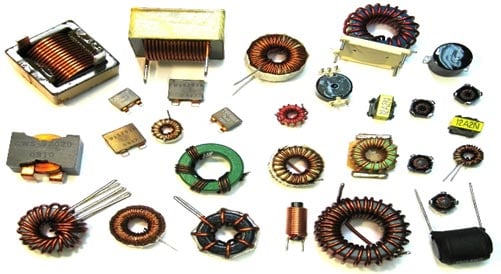
Depending on the core of the coil, inductance value changes drastically. In the figure below you can see the air-cored inductors, in these inductors, there will be no solid core. They are basically coils left in the air. The medium of flow of magnetic field generated by the inductor is nothing or air. These inductors have inductances of very less value.
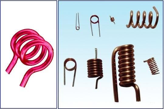
These inductors are used when the need for values of few microHenry. For values greater than few milliHenry these are not a suitable one. In below figure you can see an inductor with ferrite core. These Ferrite Core inductor has very large inductance value.
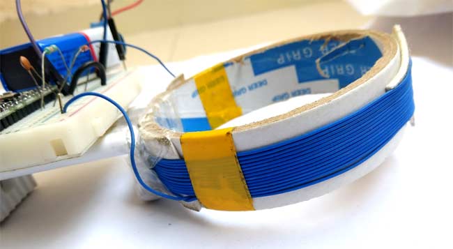
Remember the coil wound here is a air-cored one, so when a metal piece is brought near the coil, the metal piece acts as a core for the air cored inductor. By this metal acting as a core, the inductance of the coil changes or increases considerably. With this sudden increase in inductance of coil the overall reactance or impedance of the LC circuit changes by a considerable amount when compared without the metal piece.
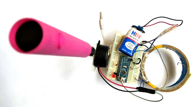
So here in this Arduino Metal Detector Project, we have to find the inductance of the coil to detect metals. So to do this we have used LR circuit (Resistor-Inductor Circuit) that we already mentioned. Here in this circuit, we have used a coil having around 20 turns or winding with a 10cm diameter. We have used an empty tape roll and wind the wire around it to make the coil.
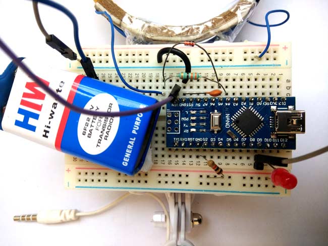
Circuit Diagram:
We have used an Arduino Nano for controlling whole this Metal Detector Project. A LED and Buzzer are used as metal detection indicator. A Coil and capacitor is used for the detection of metals. A signal diode is also used for reducing the voltage. And a resistor for limiting the current to the Arduino pin.

Working Explanation:
Working of this Arduino Metal Detector is bit tricky. Here we provide the block wave or pulse, generated by Arduino, to the LR high pass filter. Due to this, short spikes will be generated by the coil in every transition. The pulse length of the generated spikes is proportional to the inductance of the coil. So with the help of these Spike pulses, we can measure the inductance of Coil. But here it is difficult to measure inductance precisely with those spikes because those spikes are of very short duration (approx. 0.5 microseconds) and that is very difficult to be measured by Arduino.
So instead of this, we used a capacitor that is charged by the rising pulse or spike. And it required few pulses to charge the capacitor to the point where its voltage can be read by Arduino analog pin A5. Then Arduino read the voltage of this capacitor by using ADC. After reading voltage, the capacitor quickly discharged by making capPin pin as output and setting it to low. This whole process takes around 200 microseconds to complete. For better result, we repeat measurements and took an average of the results. That’s how we can measure the approximate inductance of Coil. After getting the result we transfer the results to the LED and buzzer to detect the presence of metal. Check the Complete code given at the end of this Article to understand the working.
Complete Arduino code is given at the end of this Article. In the programming part of this project, we have used two Arduino pins, one for generating block waves to be fed in Coil and second analog pin to read capacitor voltage. Other than these two pins, we have used two more Arduino pins for connecting LED and buzzer.
You can check the complete code and Demonstration Video of Arduino Metal Detector below. You can see that whenever it detects some metal the LED and Buzzer start to blink very fastly.
Complete Project Code
/*
Metal Detector Arduino Code
*/

#define capPin A5
#define buz 9
#define pulsePin A4
#define led 10
long sumExpect=0; //running sum of 64 sums
long ignor=0;   //number of ignored sums
long diff=0;        //difference between sum and avgsum
long pTime=0;
long buzPeriod=0;
void setup()
{
  Serial.begin(9600);
  pinMode(pulsePin, OUTPUT);
  digitalWrite(pulsePin, LOW);
  pinMode(capPin, INPUT);
  pinMode(buz, OUTPUT);
  digitalWrite(buz, LOW);
  pinMode(led, OUTPUT);
}
void loop()
{
  int minval=1023;
  int maxval=0;
  long unsigned int sum=0;
  for (int i=0; i<256; i++)
  {
    //reset the capacitor
    pinMode(capPin,OUTPUT);
    digitalWrite(capPin,LOW);
    delayMicroseconds(20);
    pinMode(capPin,INPUT);
    applyPulses();

    //read the charge of capacitor
    int val = analogRead(capPin); //takes 13x8=104 microseconds
    minval = min(val,minval);
    maxval = max(val,maxval);
    sum+=val;

    long unsigned int cTime=millis();
    char buzState=0;
    if (cTime<pTime+10)
    {
      if (diff>0)
        buzState=1;
      else if(diff<0)
        buzState=2;
    }
    if (cTime>pTime+buzPeriod)
    {
      if (diff>0)
      buzState=1;
      else if (diff<0)
      buzState=2;
      pTime=cTime;
    }
    if (buzPeriod>300)
    buzState=0;
    if (buzState==0)
    {
      digitalWrite(led, LOW);
      noTone(buz);
    }
    else if (buzState==1)
    {
      tone(buz,2000);
      digitalWrite(led, HIGH);
    }

    else if (buzState==2)
    {
      tone(buz,500);
      digitalWrite(led, HIGH);
    }
  }
  //subtract minimum and maximum value to remove spikes
  sum-=minval;
  sum-=maxval;

  if (sumExpect==0)
  sumExpect=sum<<6; //set sumExpect to expected value
  long int avgsum=(sumExpect+32)>>6;
  diff=sum-avgsum;
  if (abs(diff)<avgsum>>10)
  {
    sumExpect=sumExpect+sum-avgsum;
    ignor=0;
  }
  else
    ignor++;
  if (ignor>64)
  {
    sumExpect=sum<<6;
    ignor=0;
  }
  if (diff==0)
    buzPeriod=1000000;
  else
  buzPeriod=avgsum/(2*abs(diff));
}
void applyPulses()
{
    for (int i=0;i<3;i++)
    {
      digitalWrite(pulsePin,HIGH); //take 3.5 uS
      delayMicroseconds(3);
      digitalWrite(pulsePin,LOW);  //take 3.5 uS
      delayMicroseconds(3);
    }
}
Comments
what the type of wire used in project ? diameter of wire
but ? i need the think of wire used just that
plz
what is the thickness of the wire to do the Coil???
plz
Very nice project , I have successfully made it using arduino uno r3, but the only problem I have experienced is it can't detect small objects like small leds, alligator clips, .. Is it okay that I used the built in USB-B Port of arduino connected to 5k Mah power bank as power supply?
I have a UNO R3 too, is there any difference in circuit and code..Please can you help me through if there is any difference.
Bro how u build the electric wire coil
please send me the correct code
i have check the above program but it shows some error. so please mail the code sir.
I could not able to able get the exact output. My LED and buzzer are blinking as such in a some random manner. I suspect my output is not right coz, even if i keep the metal very close to it, it is not working. Please help me .....
Thanks in advance.
were you able to solve it , i am facing the same problem , please help if u r able to solve it
Can you pls help me? Can you send me the picture of the breadboard, wires and other components in it?
I m using coil , not wire it help me or not...if it can't help me which wire I used breadboard wire...
Plz tell me ...plz
Coil should have also worked, just make sure if it is enameled!! The wire used here is normal breadboard wire
high qaulity
capacity
hi.
can i use different diameter of tape to measure the sensitivity of the search coil? or it will effect the faulty of circuit?
please send me the correct coad for this project but its shows some errors.
i made the circuit, but the buzzer always makes noise and when a metal is here, nothing happens. So it doesn't work. Help please !
I was going to do this for a school project and was wondering if the size of the tape thing that you wrap the wire around could effect the ability to detect metals?
hey guys !pls reply
I am unable to find a 10nf capacitor and somebody told me to use 10pf capacitor.so,tell me will that go with the metal detector ?will it work?pls...reply fast..
circuit digest has helped me a lot with my project ..
just need one more help .. pls reply..
@akshata oak
There are many ways of defining capacitors. They are usually defined as nanofarads, picofarads, and microfarads. Essentially it's the same thing, with the decimal place in a different location.
The idea is to end up with a number that makes sense (i.e., that isn't too large or too small).
For example; these are actually all the same value:
10nf (nanofarads)
10000pF (picofarads)
0.01uF (microfarads)
You should be able to find an inexpensive ceramic capacitor with that value.
The capacitor may also be labelled with a three number code. In your case you would want a capacitor labelled 103.
In such a case the capacitor is measured in picofarads. The first two digits represent the first two values for the capacitor, and the 3 represents the number of extra zeros.
103 becomes 10 + 000 (3 zeroes) = 10 nF = 10000 pF = 0.01uF
I hope this helps.
WE ARE DOING A METAL DETECTOR PROJECT FOR MY M.SC COURSE
BUT YOUR CODE DOES NOT SUPPORT FOR THIS PROJECT SO I REQUEST YOU TO PLEASE SEND US CORRECT CODE. THANKING YOU
why is this circuit not working all instructions are followed but not work so how can we follow you?
Please what's the thickness of the the coil used in the project
how can the range of it can be increased such that it can be used for searching the metal objects buried inside soil of about 1 m range..?
thanks in advance
Please can I have the full work on this project. Thank you
can i wound the copper wire as a coil around the tape roll and if i disconnected the arduino from pc how it works can you explain me
Great job, code worked at first, schematic very clear.
After an initial mistake (wrong capacitator, realized reading comments...I am a Pharmacist after all ) works perfectly.
Hi,
Is there any chance you could send me a picture of your breadboard connections please
Hello, Sir Giorgio!
I want to ask for your help. Could you let me know if how did you let the metal detector work? Also I would like to have the copy of your code. Please, sir. Help me. It's my project and I need to do this so I can pass in muy subject. I'm hoping for your good heart, sir.
hi ,
it's good job , many thanks for you
my quasition is can we isolate the detection for some meatl ? like detecte just the iron metal
Hi,
I am trying to complete this project but I am very new to coding and circuitry. Could anyone share more details to help me?
I am not sure I have connected all the parts in the right way and I am afraid to plug in the code in case I blow it.
Does the size of the coild effect the current flwoing through the arduino?
When I do an online checker of the code it says that I have a lone wrong...
Thanks for your help. I would really like to make this project work.
The code is working and uploaded correctly.
I pplugged it into power supply but nothing works. I am sure it is my connections... Any ideas?
Dear Saddam
in your program
if (sumExpect==0)
sumExpect=sum<<6; //set sumExpect to expected value
long int avgsum=(sumExpect+32)>>6;
diff=sum-avgsum;
Can you explain this ? its meaning less because shift left 6 places and 32 and shift right 6 place has no differance.
while i was able to upload the code succesfully the led blink and buzzer sound are random in nature , it is not sure that code is working properly or not , please help me here if there is any change in actual circuit from the given one , also i am using arduino leanardo (olimaxino 32u4) , do i need to change anything in the code for olimaxino ?
i really could use a help here , i have to present this as a real time master project for one of my subject
is ir okay if i will use Arduino Uno?
can someone please send me a video tutorial on this?
Could someone send the right source code, please?
The original code and circuit are correct.
My LED and buzzer seem to be working fine but there is no change in sound when a metal is brought near coil. So i presume the coil ( I used enameled copper) isn't working. Please what do I do? Thanks.
Can someone please explain this part,
if (cTime<pTime+10)
{
if (diff>0)
buzState=1;
else if(diff<0)
buzState=2;
}
if (cTime>pTime+buzPeriod)
{
if (diff>0)
buzState=1;
else if (diff<0)
buzState=2;
pTime=cTime;
}
if (buzPeriod>300)
buzState=0;
if (buzState==0)
{
digitalWrite(led, LOW);
noTone(buz);
}
else if (buzState==1)
{
tone(buz,2000);
digitalWrite(led, HIGH);
}
else if (buzState==2)
{
tone(buz,500);
digitalWrite(led, HIGH);
}
}
how can the range of it can be increased such that it can be used for searching the metal objects buried inside soil of about 1 m range..?
thanks in advance
Sono nuovo del caricamento dei dati, chiedo cortesemente quale e il programma usare, da installare sul p.c. e connetere ad arduino nano per caricarci il codice.
ti ringrazio
I've done this circuit, but the buzzer is always making noise. It becomes silent when I remove the A5 pin, it continues to sound after 2-3 seconds when I insert it again. Can someone solve this problem, please help?This is the subject of my last homework, I have almost no knowledge.
If I ask you, how many khz does this circuit work with?
How can I make the operating frequency 100 khz?
Please send me the synopsis and full details of the project sir..