
Short circuit protection is an unintended connection between two terminals which are supplying power to the load. It can happen both in an AC and a DC circuit. If it is an AC supply, then a short circuit can trip the power supply of the whole area, but there are fuses and overload protection circuits at many levels, from the power station to the house. And if it is a DC source like a battery, then it can heat the battery, and the battery will be discharged very quickly. In some cases battery can explode. There are a lot of ways to protect circuits from short-circuit, and many types of fuses are available for overload protection. This comprehensive guide covers building a simple yet effective short circuit protection circuit for DC applications, complete with circuit diagrams, component specifications, and detailed working principles.
We are going to design and study a simple low-voltage Short-circuit protection circuit for DC voltage. The circuit is designed with the purpose of running a microcontroller circuit safely and can protect it from damage due to a short-circuit in another part of the circuitry.
Table of Contents
What is Short Circuit Protection and Why is it Essential?
A short circuit protection device, as the name implies, is a safety device designed to safeguard electrical circuits from short circuits. It is capable of detecting an excessive current flow and automatically disconnecting the electrical power. The positive and negative terminals may be coupled with each is capable of delivering harmful current levels which can lead to component damage, fire outbreaks, or battery explosions.
We want to design a reliable short circuit protection module specifically for microcontroller circuits, which are low-power DC devices, and which require a well-regulated power supply that is short circuit protected.
AC vs DC Short Circuit Protection Comparison
| Parameter | AC Circuits | DC Circuits |
| Protection Method | Circuit breakers, Fuses | Electronic protection circuits |
| Response Time | Fast (milliseconds) | Very fast (microseconds) |
| Consequences | Area power outage | Component damage, battery heating |
| Recovery | Manual reset required | Automatic or manual reset |
Components Required for Short Circuit Protection Circuit
This short circuit protection circuit diagram uses commonly available components for cost-effective implementation:
- SK100B PNP transistor - 1Nos.
- BC547B NPN transistor - 1Nos.
- 1kΩ Resistor - 1Nos.
- 10kΩ Resistor - 1Nos.
- 330Ω Resistor - 2Nos.
- 470Ω Resistor - 1Nos.
- Power supply 6VDC - 1Nos.
- Breadboard - 1Nos.
- Connecting wires - As per the requirement
SK100B PNP Transistor
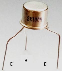
Starting from the notch of the transistor emitter, the middle is the base, and the last is the Collector
- Emitter - E
- Base - B
- Collector - C
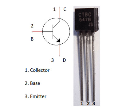
BC547B NPN transistor
Short Circuit Protection Circuit
A common example of a short circuit is when the positive and negative terminals of a battery are connected with a low-resistance conductor, like a wire. In this condition, the battery can be set to fire and can even explode. That’s what happens with mobile batteries in mobiles many times.
To avoid this short-circuit condition, a Short-circuit Protection Circuit is used. The short-circuit Protection Circuit will divert the flow of current or break the contact between the circuit and the power source.
Sometimes we experience a power failure with a sudden spark while using some faulty home appliances like an oven, an iron, etc, then. The reason behind this is that somewhere there is some excess current flowing through some circuit inside that faulty appliance. This may lead to shock or could fire up the house if not protected. So a fuse or circuit breaker is used in order to avoid such damage. In such a condition circuit breaker or fuse disconnects the main supply to the house. A fuse breaker circuit is also a form of short-circuit protection circuit, in which a low-resistance wire is used, which melts and disconnects the main power supply to the house whenever there is excess current passing through it.
So here we are going to study and design a circuit to avoid the damage due to a short circuit in it.
Short Circuit Protection Circuit Diagram & Design Analysis


Working Principle of Short Circuit Protection Device
A simple low-power DC Short-circuit Protection Circuit is shown above, which consists of two transistor circuits, one is a BC547 NPN transistor circuit, and the other is a SK100B PNP transistor circuit. The input is provided to the circuit using a 5V DC Power supply, which can be either provided by a battery or using transformer.
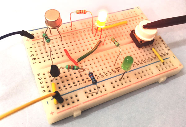
The working of the circuit is simple; when Green LED D1 glows means the circuit is functioning normally and there is no risk of damage. The Red LED D2 is expected to glow only when there is a short circuit.
When the power supply is turned ON, transistor Q1 gets biased and starts conducting, and LED D1 turns ON. During this time, Red LED D2 remains off as there is no Short-circuit.
The glowing of the Green LED D1 also indicates that the supply voltage and output voltage are approximately equal.
In our stimulation circuit, we have generated a ‘short’ using a switch at the output. When the ‘short’ occurs, the output voltage drops to 0V and Q1 stops conducting as its base voltage is 0V. Transistor Q2 also stops conducting as its collector voltage drops to 0V.
So now current is starting to flow through the RED LED D2 and pass through the ground via the short circuit path (through the switch). That makes the Red LED D2 start conducting as it is forward biased, and indicates that a short has been detected and the current is diverted through the RED LED D2 instead of damaging the entire circuit.
Applications and Implementation
This overcurrent protection module is utilised in various electronic systems requiring safe overcurrent protection:
Common Uses
» Microcontroller Projects: ESP32 power protection, Raspberry Pi, Arduino
» Battery-Powered Devices: IoT devices, portable electronics
» Prototype Circuits: Test and development environments
» Education: Electronics experimentation and learning
» Low-Power Systems: Sensor networks and monitoring equipment
Troubleshooting Common Issues and Solutions
| Problem | Possible Cause | Solution |
| Neither LED glows | No power supply or faulty connections | Check power connections and supply voltage |
| Only Red LED glows | Permanent short circuit or faulty Q1 | Check output for shorts, test Q1 transistor |
| Both LEDs glow dimly | Insufficient supply voltage | Ensure minimum 5V supply voltage |
| No output voltage | Faulty SK100B or incorrect wiring | Verify transistor connections and functionality |
| False triggering | Noise or voltage fluctuations | Add filter capacitors across supply |
Frequently Asked Questions - Short Circuit Protection Circuit
⇥ 1. How much current can the short circuit protection handle at maximum?
The circuit can safely handle a maximum of 300mA continuous current, according to the specifications of the SK100B PNP transistor. Higher currents can be accommodated with the use of power transistors, with an appropriate heat sink.
⇥ 2. Can this circuit work in a 3.3V microcontroller system?
The circuit is designed to be used in the range of 5-6V, but it should also work in a 3.3V microcontroller system, although probably not as effectively. If used at 3.3V, consider using low-dropout transistors to improve the performance.
⇥ 3. How fast does the short circuit protection function respond to faults?
The electronic protection will respond within 10 microseconds of a short circuit fault condition, which is in comparison to traditional fuses that can take many milliseconds to respond and make the disconnection.
⇥ 4. What occurs after the short circuit condition is removed?
Once the short circuit has been removed, the circuit should perform as originally designed. The green LED should have come back on and should indicate that the circuit is functioning correctly.
⇥ 5. Can I use this circuit or modify it to work as an AC system?
This circuit is designed for DC use, as mentioned before. In an AC system, there are other methods of protecting the circuit against short circuits. This typically includes circuit breakers and/or GFCI, and there are also other kinds of AC protection circuits.
Practical Circuit Design Projects
Explore our past projects to see how circuits have been practically implemented in the links below.

This guide will explain how to build a digital dice circuit using a 555 timer IC and a 4017 IC. To create this digital dice circuit, we have mainly used a 555 timer IC and a 4017 IC. You can also check this digital dice circuit using Arduino.

Reverse Car Parking Sensor Circuit
To design this car parking system circuit, we placed an IR transmitter and receiver pair at the rear side of the car. IR transmitter transmits an Infrared signal or rays into the environment.

In this project, we are going to design a simple metal detector circuit. There are so many metal detector designs, but most of them are complex in design, so here we are going to design a simple metal detector circuit using a 555 Timer IC.
Comments
Hello, and thank you for your wonderful effort for the benefit of us beginners in electronics.
I would suggest that you create an app regarding this, as I could not find one on play store.
Good morning sir. How can this circuit be modified for use in 12v appliance? I'm a novice in electronics and want to build it. Thanks.
Sir, in our country it is difficult to find sk100 or ck00 nowadays. could you please give me a suggestion for it?
Thank you.

Good and it's very useful,this generation students use more this type of informations.