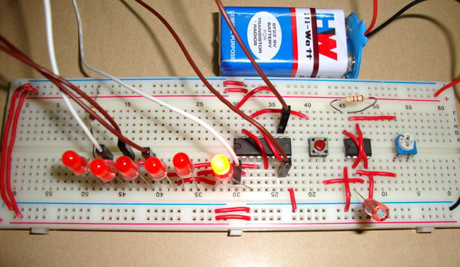
Dice can be used to play several games, such as Snakes and Ladders, Ludo, etc. Generally, dice are made of wood or plastic, which gets distorted over time and becomes biased. A digital dice circuit is an alternative to the traditional dice; it can’t be biased or distorted, and it acts so fast that nobody would be able to cheat.
This guide will explain how to build a digital dice circuit using a 555 timer IC and a 4017 IC. To create this digital dice circuit, we have mainly used a 555 timer IC and a 4017 IC. You can also check this digital dice circuit using Arduino.
Table of Contents
- Understanding the 4017 IC
- How the 4017 IC Works in a Digital Dice Circuit?
- Required Components
- Circuit Diagram and Working Principle
- └ Circuit Operation Explained
- └ 555 Timer for Clock Generation
- Arduino Versus Digital Dice
- Troubleshooting
- Applications and Modifications
- Frequently Asked Questions
- Conclusion
- Explore More
Understanding the 4017 IC for Digital Dice Applications
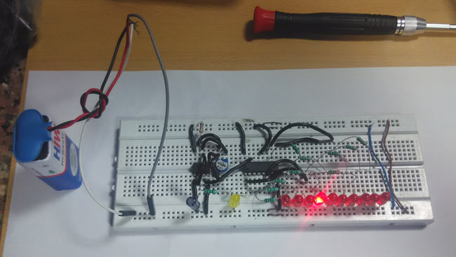
4017 IC is a CMOS decade counter chip. When powered, it can output at 10 pins (Q0-Q9) in sequence, which means it will produce an output at the 10 output pins one after the other. The sequential output here comes from the clock pulse at PIN 14, which makes it perfect for our digital dice project for random number generation.
How the 4017 IC Works in a Digital Dice Circuit?
At first, output at Q0 (PIN 3) is HIGH, then with each clock pulse from the 555 timer IC, the output advances to the next PIN. Like one clock pulse makes the Q0 LOW and Q1 HIGH, and then the next clock pulse makes the Q1 LOW and Q2 HIGH, and so on. After the Q9, it will start from the Q0 again. So it creates sequential ON and OFF of all 10 OUTPUT PINs. Below is the PIN diagram and PIN description of 4017:
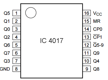
PIN NO. | PIN Name | PIN Description |
1 | Q5 | Output 5: Goes high in 5 clock pulse |
2 | Q1 | Output 1: Goes high in 1 clock pulse |
3 | Q0 | Output 0: Goes high at the beginning – 0 clock pulse |
4 | Q2 | Output 2: Goes high in 2 clock pulse |
5 | Q6 | Output 6: Goes high in 6 clock pulse |
6 | Q7 | Output 7: Goes high in 7clock pulse |
7 | Q3 | Output 3: Goes high in 3 clock pulse |
8 | GND | Ground PIN |
9 | Q8 | Output 8: Goes high in 8 clock pulse |
10 | Q4 | Output 4: Goes high in 4 clock pulse |
11 | Q9 | Output 9: Goes high in 9 clock pulse |
12 | CO –Carry out | Used to cascade another 4017 IC to makes it count upto 20, it is divide by 10 output PIN |
13 | CLOCK inhibit | Clock enable pin, should kept LOW, keeping HIGH will freeze the output. |
14 | CLOCK | Clock input, for sequentially HIGH the output pins from PIN 3 TO PIN 11 |
15 | RESET | Active high pin, should be LOW for normal operation, setting HIGH will reset the IC (only Pin 3 remain HIGH) |
16 | VDD | Power supply PIN (5-12v) |
Required Components for Digital Dice Circuit
Building this digital dice circuit using a 555 timer requires the following components:
- CD4017 IC
- 555 Timer IC
- 2 Resistor- 1k
- Capacitor- 10uF
- Variable Resistor- 10K
- Push Button
- 6 LEDs
- Battery - 9V
Digital Dice Circuit Diagram and Working Principle
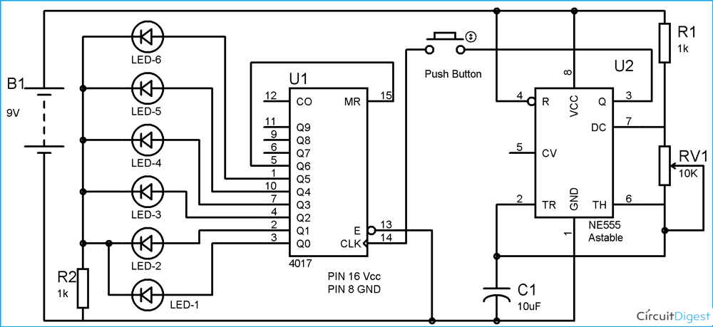
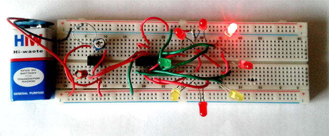
In this digital dice circuit, we have used 6 LEDs, each LED represent a number (1-6) of Dice. LEDs start flashing as we press the Push button and stop when we release it. After release, the illuminated LED tells the numbers you got on Dice. Like if fifth no. LED remains ON after releasing the button, which means you got 5 on Dice. We have connected 6 LEDs to the outputs Q0 to Q5, and the seventh output Q6 is connected back to the RESET PIN 15. So that after LED 6, it starts from the First LED at Q0.
To apply the clock pulse at PIN 14 of the 4017 IC, we have used a 555 timer IC in Astable mode. The oscillated output generated at PIN 3 of 555 has been applied to PIN 14 of 4017, so that the output can be advanced with each clock pulse.
Circuit Operation Explained
Here in this digital dice circuit diagram, we have employed 6 LEDs, and each LED shows a number (1-6) of the dice. The operation of the circuit is:
LED Control: LEDs will activate and flash when you press the push button switch, and will stop when you release the push button switch
Random Number Output: Upon release of the push button switch, the lit LED displays the number of the dice you rolled
Reset: We connect 6 LEDs to outputs Q0 to Q5, and the seventh output Q6 is connected to the RESET PIN 15
Continuous Rotation: After LED 6, the display will immediately cycle to the first LED, which would be output Q0
555 Timer for Clock Generation
To create clock pulses at PIN 14 of the 4017 IC, we will configure the 555 timer IC in astable operational mode. The output that oscillates at PIN 3 of the 555 timer connects to PIN 14 of the 4017 IC, counting the output with each clock pulse.
Frequency Control and Randomisation
The flashing speed of LEDs is controlled by the potentiometer (RV1), varying the oscillation frequency of the 555 timer.
The frequency of the 555 can be calculated using this formula: F=1.44/((R1+2*RV1)*C1)
We make the frequency of oscillation high enough so that nobody can guess or cheat the result. The speed of flashing the LED is in direct proportion to the oscillation frequency of the 555 timer - the higher the frequency, the faster the flashing and the improved randomisation.
Arduino Versus Digital Dice
Although this digital die circuit using the 555 timer IC had simplicity on its side, together with reliability, one could also use a digital dice circuit with Arduino for even more benefits. The Arduino version supports:
- Programmable patterns
- Multiple dice simulation
- Digital display integration
- Sound effects
The 555 timer method, however, provides:
- Lower cost
- Higher reliability
- No programming needed
- Instant action
Troubleshooting Your Digital Dice Circuit
Common Issues and Solutions
» LEDs not lighting: Check power connections and LED polarity
» No sequential action: Check 4017 IC wiring and clock pulse
» Irregular flashing: Change the potentiometer or verify the capacitor value. Circuit not resetting: Verify Q6 correctly connects to the RESET pin
Applications and Modifications
This digital dice circuit may be adapted to different applications:
∗ Board game automation
∗ Educational demonstrations
∗ Random number generation
∗ Probability experiments
∗ Gaming accessories
Frequently Asked Questions on Digital Dice Circuit using 555 Timer
⇥ What is a digital dice circuit?
A digital dice circuit utilises a 555 timer to produce clock pulses which drive a 4017 decade counter IC. The counter sequentially illuminates 6 LEDs, which represent the multiple numbers of the dice or die from 1 through 6. When a button is pressed and released, the LED that is illuminated when the button is released represents the result of your dice roll.
⇥ What advantage do digital dice have over physical or regular dice?
Digital dice cannot be biased or deformed like physical wooden or plastic dice. They operate at high frequencies, which removes any opportunity of cheating, allows consistent randomisation, and will not wear out with usage, compromising fairness. Digital dice will last indefinitely.
⇥ Can I change my digital dice circuit speeds?
Yes, it can. A potentiometer (RV1) in the circuit controls the oscillation frequency of a 555 timer. Rotation of the potentiometer varies the speed of the LED flashing; hence, you can just adjust according to your taste on how fast they should flash.
⇥ What circuit components are the most vital?
The following components are vital to build a digital dice circuit and include: a 555 timer IC; a 4017 decade counter IC, 6 LEDs; a push button; 10µF capacitor; two 1kΩ resistors; a 10kΩ potentiometer; a 9V battery; and connecting wires. All components can be found easily and are relatively inexpensive.
⇥ What is the purpose of using the 4017 IC in a digital dice circuit?
The 4017 IC is a CMOS decade counter that outputs HIGH signals sequentially on 10 pins (Q0-Q9). In dice use, only 6 outputs (Q0-Q5) correspond to numbers 1-6, and we connected Q6. The Q6 output resets the 4017 circuit and makes a nice 6-number cycle.
⇥ How do I troubleshoot my digital dice circuit if it doesn't work?
Typical issues with digital dice circuits include: LED polarity and power connections; 4017 IC wiring; clock signal on the 555 timer; the reset connection from Q6 to pin 15; and lastly, the button works.
Conclusion
This digital dice circuit utilises a 555 timer for a great introduction to digital electronics while building something useful. The combination of the 555 timer IC and the 4017 decade counter makes a true and reliable dice that is cheat-proof for games or educational purposes. The high speed of the circuit makes it truly random, and the simple design allows easier access to digital electronics. If you are learning electronics or simply need a fair dice (for fun), this circuit should perform consistently, and it uses very limited components.
In this digital dice circuit, we have kept the oscillation frequency so high that no one can cheat. LED flashing speed is directly proportional to the oscillation frequency of 555, as the frequency increases, as higher the speed of flashing. You can increase the frequency according to you by rotating the potentiometer.
Explore More Exciting 555 Timer and Digital Counter Projects
Build your electronics skills with these captivating 555 timer and digital counting circuits. From classic LED chasers to interactive seven-segment counters and roulette-style randomizers, these projects expand on timing and counting concepts, perfect for hobbyists eager to experiment with IC555-based designs.
7 Segment Display Counter using IC 555 Timer IC
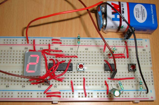
Digital counters are needed everywhere in this digital world, and 7 segment display is one the best component to display the numbers. Counters are needed in object/products counters, digital stopwatches, calculators, timers etc. To use the 7 segment with ease, there is a 7 segment driver IC which is IC CD4026, so we are building 7 segment counter circuit using 4026 IC.
LED Chaser Circuit using IC 555
You must have seen different kinds of decoration lighting patterns. In this LED chaser circuit, we have created an interesting LED blinking pattern by using a 555 timer IC and Counter IC CD 4017.
LED Roulette circuit using 555 timer IC
Here we are going to show you how to make an LED Roulette Circuit using 555 timer IC. Roulette is a casino game named after the French word which means little wheel.
Comments
I want to know the circuit diagram of digital dice by using 7segment display. please send to my mail. Thanks!



How can I control the resistance by remote? Please reply.