

An average household microwave oven operating at 110/220V AC can produce upto 2800V inside it, which is dangerously lethal. Besides that it also has a lower level AC voltage around 3.5V to light up the filament and a regulated DC voltage like 5V/3.3V for the digital electronics part like the display or timers to operate. Have you ever wondered what prevents these high voltages from reaching out to your fingers through the buttons or casing when you touch the oven? The answer to your question is “isolation”. When designing electronics products involving more than one type of signal or more than one operating voltage, isolation is used to prevent one signal from messing up the other. It also plays a vital role in safety by preventing fault conditions in industrial-grade products. This isolation is generally referred as Galvanic isolation. Why the term “Galvanic”? It is because galvanic represents the current produced by some sort of chemical action, and since we are isolating this current by breaking conductor contact it is called as Galvanic Isolation.
There are several types of galvanic isolation techniques and choosing the right one depends on the type of isolation, withstanding capacity, application requirements and obviously, the cost factor is also involved. In this article we will learn about the different types of isolation, how they work and where to use them in our designs.
Types of Galvanic Isolation
- Signal Isolation
- Power Level Isolation
- Capacitors as an Isolator
Signal Isolation
Signal level isolation is required where two circuits of different nature are communicating with each other using some type of signal. For example, two circuits using independent power source and operating of different voltage levels. In such cases, to isolate the individual ground of two independent power sources and to communicate between those two circuits, signal level isolation is required.
Signal isolation is done by using different type of isolators. Optical and electromagnetic isolators are majorly used in signal isolation purpose. Both these isolators protect the different ground sources from combining together. Each Isolator has its own unique operating principle and application which are discussed below.
1. Optical-Isolators
Optical isolator uses lights to communicate between two independent circuits. Typically, optical isolators a.k.a Optocoupler have two components inside a single silicon chip, a light emitting diode, and a phototransistor. The LED is controlled by the one circuit and the transistor side is connected with the other circuit. Therefore, the LED and the transistor are not electrically connected. The communication is only done by lights, optically.
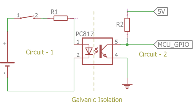
Consider the above image. A popular optoisolator PC817 is isolating two independent circuits. Circuit 1 is the power source with a switch, circuit 2 is a logic level output connected with a different 5V supply. The logic state is controlled by the left circuit. When the switch is being closed, the LED inside the optocoupler lights up and turns on the transistor. The logic state will be changed from High to Low.
The circuit 1 and circuit 2 are isolated using the above circuit. Galvanic isolation is very useful for the above circuit. There are several situations where the high potential ground noise induced in the low potential ground and creates a ground loop which further responsible for inaccurate measurements. Similar to PC817 there are many types of Optocoupler for different application requirements.
2. Electromagnetic Isolators
Optoisolators are useful for DC signal isolation, but electromagnetic isolators such as small signal transformers are useful for AC signal isolation. Transformers like audio transformer have their primary and secondary sides isolated which can be used for different audio signal isolation. Another most common use is in network hardware or Ethernet section. Pulse transformers are used to isolate the external wiring with internal hardware. Even telephone lines are used transformer based signal isolators. But, as transformers are isolated by electromagnetically, it only works with AC.
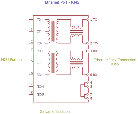
Above image is the internal schematic of RJ45 jack with integrated pulse transformer for isolating MCU portion with the Output.
Power Level Isolation
Power level isolations are required to isolate low power sensitive devices from high power noisy lines or vice versa. Also, power level isolation provides proper safety from hazardous line voltages by isolating the high voltage lines from the operator and other parts of the system.
1. Transformer
The popular power level isolator is again a Transformer. There are enormous applications for transformers the most commonly usage is to provide low voltage from a high voltage source. The transformer does not have connections between primary and secondary but could step down the voltage from high voltage AC to low voltage AC without losing the galvanic isolation.
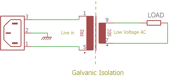
The above image is showing a step-down transformer in action where the primary side input is connected into the wall socket and the secondary is connected across a resistive load. A proper isolation transformer has a 1:1 turns ratio and do not alter the voltage or current level on both sides. The sole purpose of the isolation transformer is to provide isolation.
2. Relays
Relay is a popular isolator with a huge application in the field of electronics and electrical. There are many different types of relays available in the electronics market depending on the application. Popular types are Electromagnetic relays and solid state relays.
An Electromagnetic relay works with Electromagnetic and Mechanically movable parts often referred to as poles. It contains an electromagnet that moves the pole and completes the circuit. Relay creates isolation when high voltage circuits need to be controlled from a low voltage circuit or vice-versa. In such a situation both circuits are isolated but one circuit could energize the relay to control another one.
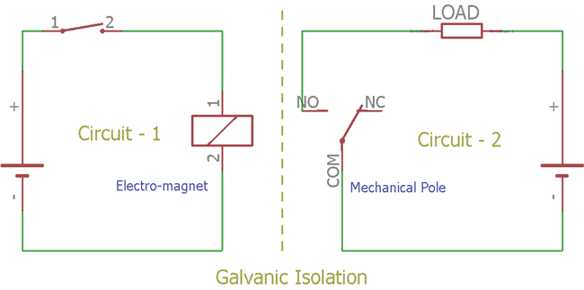
In the above image, two circuits are electrically independent of each other. But by using the switch on Circuit-1, user can control the state of the load on the circuit 2. Learn more about how a relay can be used in a Circuit.
There are not much difference between Solid State Relay and electromechanical relay in terms of working. Solid state relays work exactly the same but the electro-mechanical part is replaced with an optically controlled diode. The galvanic isolation can be build up due to the absence of a direct connection between the input and output of the solid state relays.
3. Hall Effect Sensors
Needless to say that current measurement is a part of Electrical and Electronics engineering. There are different types of current sensing methods available. Often the measurements are required for High voltage and High current paths and the value read has to sent to a low voltage circuitry which is a part of the measurement circuit. Also from the user perspective, invasive measurement is dangerous and impossible to implement. Hall Effect sensors provide contactless current measurement accurately and help to measure the current flowing through a conductor in a non-invasive way. It provides proper isolation and ensures safety from hazardous electricity. Hall Effect sensor uses electromagnetic field generated across the conductor to estimate the current flowing through it.
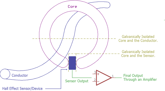
The core ring is hooked over a conductor in a noninvasive way and it is electrically isolated as shown in the picture above.
Capacitors as an Isolator
The least popular method for isolating circuits is by using capacitors. Due to inefficiency and dangerous failure outcomes this is no longer preferred, but still knowing it might come in handy when you want to build a crude isolator. Capacitors block DC and allow passing a high-frequency AC signal. Due to this excellent property, the capacitor is used as isolators in designs where DC currents of two circuits need to be blocked but still allowing the data transmission.
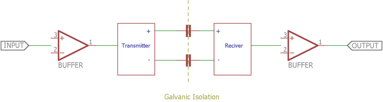
The above image is showing capacitors are used for isolation purposes. Transmitter and the receiver both are isolated, but the data communication can be done.
Galvanic isolation – Applications
Galvanic isolation is very essential and the application is huge. It is an important parameter in consumer goods as well as in the Industrial, Medical, and communication sector. In an industrial electronics market, galvanic isolation is required for Power Distribution systems, Power generators, measurement systems, Motor controllers, Input-Output logic devices, etc.
In the medical sector, isolation is one of the major priorities for the equipment as medical devices can be directly connected with the patient’s bodies. Such devices are ECG, Endoscopes, Defibrillators, different kinds of imagining device. Consumer level communication systems also use galvanic isolation. One common example is Ethernet, Routers, Switchers, Telephone switches, etc. Normal consumer goods, like chargers, SMPS, computer’s logic boards are the most common products which use galvanic isolation.
Practical Example of Galvanic isolation
The below circuit is a typical application circuit of galvanically isolated Full-duplex IC MAX14852 (For 500 kbps communication speed) or MAX14854 (For 25 Mbps communication speed) on RS-485 communication line with the micro-controller unit. The IC is manufactured by the popular semiconductor manufacturing company Maxim Integrated.
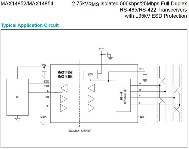
This example is one of the best examples of galvanic isolation example on industrial equipment. RS-485 is a widely used traditional communication protocol used in industrial equipment. The popular use of RS-485 is to employ MODBUS protocol over TTL segment.
Suppose a High voltage AC transformer is providing sensors data which are installed inside the Transformer via RS-485 protocol. One needs to connect a PLC device with an RS-485 port to harvest the data from the transformer. But the problem is in the direct communication line. PLC uses very low voltage level and very sensitive with the high ESD or surge. If a direct connection is employed, the PLC can be at high risk and need to be galvanically isolated.
Those ICs are very useful to protect the PLC from ESD or surges.
As per the datasheet, Both ICs has a withstand capacity of +/- 35kV ESD and 2.75kVrms withstand isolation voltage up to 60 seconds. Not only this, but those ICs also confirm 445Vrms Working-isolation Voltage, making it a suitable isolator to be used in industrial automation equipment.
