

In a voltage-controlled current source circuit, as the name implies, a small amount of voltage across the input will proportionally control the current flow across the output loads. This type of circuit is commonly used in electronics to drive current-controlled devices like BJT, SCR, etc. We know that in a BJT the current flowing through the base of the transistor controls how much transistor is closed, this base current can be provided by many types of circuit, one method is to use this voltage controlled current source circuit. You can also check the constant current circuit which can also be used to drive current-controlled devices.
In this project, we will explain how a voltage-controlled current source using op-amp can be designed and also build it to demonstrate its working. This type of voltage-controlled current source circuit is also called a current servo. The circuit is very simple and can be constructed with a minimum number of components.
Basics of Op-Amp
To understand the working of this circuit it is essential to know how an operational amplifier works.
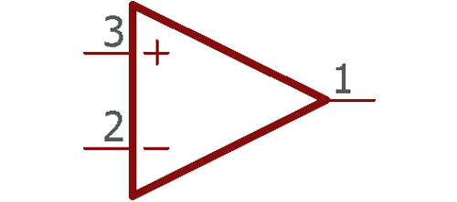
The above image is a single operational amplifier. An amplifier amplifies signals, but other than amplifying signals it can also do mathematical operations. Op-amp or Operational Amplifier is the backbone of Analog Electronics and is used in many applications, such as Summing Amplifier, differential amplifier, Instrumentation Amplifier, Op-Amp Integrator, etc.
If we look closely in the above image, there are two inputs and one output. Those two inputs have + and - sign. The positive input is called as noninverting input and the negative input is called inverting input.
The first rule the amplifier used to work is to make the difference between these two inputs is always zero. For better understanding let's see the below image -
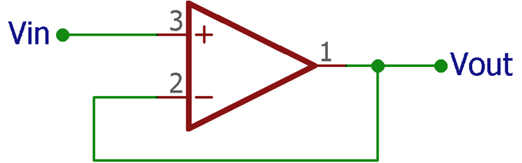
The above amplifier circuit is a voltage follower circuit. The output is connected in the negative terminal making it a 1x gain amplifier. Therefore, the voltage given across the input is available across the output.
As discussed before, the operational amplifier makes the differentiation of both input 0. As the output is connected across the input terminal, the op-amp will produce the same voltage that is provided across the other input terminal. So, if 5V is given across the input, as the amplifier output is connected at the negative terminal it will produce 5V which eventually proves the rule 5V – 5V = 0. This happens for all negative feedback operation of amplifiers.
Designing a Voltage Controlled Current Source
By the same rule, let’s see the below circuit.
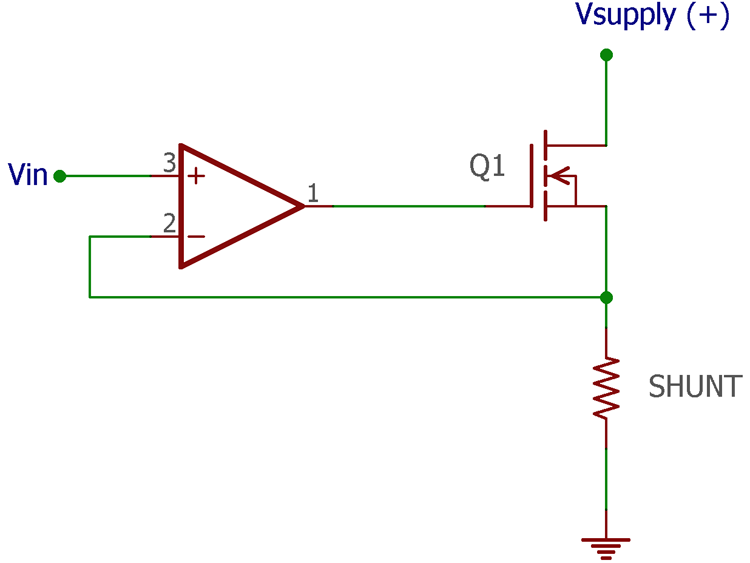
Now instead of the output of the op-amp connected to the negative input directly, negative feedback is derived from the shunt resistor connected across an N channel MOSFET. The op-amp output is connected across the Mosfet gate.
Let’s assume, 1V input is given across the positive input of the op-amp. The Op-amp will make the negative feedback path 1V at any cost. The output will turn on the MOSFET to get 1V across the negative terminal. The rule of the shunt resistor is to produce a drop voltage as per Ohms law, V= IR. Therefore, 1V drop voltage will be produced if 1A of current flow through the 1 Ohm resistor.
The op-amp will use this drop voltage and get the desired 1V feedback. Now, if we connect a load that requires current control for operation, we can use this circuit and place the load at an appropriate location.
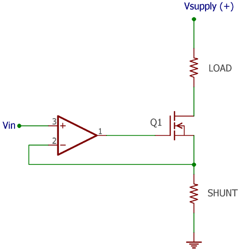
The detailed circuit diagram for Op-Amp Voltage controlled current source can be found in the below image –

Construction
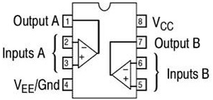
To construct this circuit, we need an op-amp. LM358 is a very cheap, easy to find op-amp, and it is a perfect choice for this project, however, it has two op-amp channels in one package, but we need only one. We have previously built many LM358 based circuits you can also check them out. The below image is an overview of the LM358 pin diagram.
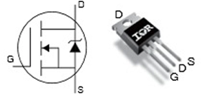
Next, we need an N Channel MOSFET, for this IRF540N is used, other MOSFETs will also work, but make sure that the MOSFET package has an option to connect additional heat sink if required and careful consideration is needed for selecting the appropriate specification of the MOSFET as required. IRF540N pinout is shown in the below image –
The third requirement is the shunt resistor. Let's stick into 1ohms 2watt resistor. Additional two resistors are required, one for the MOSFET gate resistor and the other one is the feedback resistor. These two are required for reducing the loading effect. However, the drop between these two resistors is negligible.
Now, we need a power source, it is a bench power supply. There are two channels available in the bench power supply. One of them, the first channel is used to provide power to the Circuit and the other one which is the second channel used to provide the variable voltage to control the source current of the circuit. As the control voltage is applied from an external source, both channels need to be in the same potential, thus the ground terminal of the second channel is connected across the first channel ground terminal.
However, this control voltage can be given from a variable voltage divider using any kind of potentiometer. In such a case, a single power supply is sufficient. Therefore, the following components are required to make a voltage-controlled variable current source -
- Op-amp (LM358)
- MOSFET (IRF540N)
- Shunt Resistor (1 Ohm)
- 1k resistor
- 10k resistor
- Power supply (12V)
- Power supply unit
- Bread Board and additional connecting wires
Voltage Controlled Current Source Working
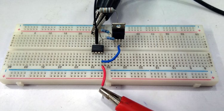
The circuit is constructed in a breadboard for testing purposes as you can see in the below image. The load is not connected in the circuit to make it a near-ideal 0 Ohms (shorted) for testing the current control operation.
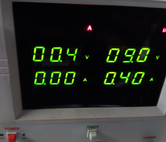
The input voltage is changed from 0.1V to 0.5V and the current changes are reflected in the other channel. As seen in the below image, 0.4V input with 0 current draws is effectively made the second channel to draw 400mA of current at 9V output. The circuit is powered using a 9V supply.
You can also check the video at the bottom of this page for detailed working. It is responding depending on the input voltage. For example, when the input voltage is .4V, the op-amp will respond to have the same voltage .4V in his feedback pin. The output of the op-amp turn on and control the MOSFET until the voltage drop across the shunt resistor became .4V.
The Ohms law is applied in this scenario. The resistor will only produce .4V drop if the current through the resistor will 400mA (.4A). This is because Voltage = current x resistance. Therefore, .4V = .4A x 1 Ohm.
At this scenario, if we connect a load (resistive load) in series same as like described in the schematic, in between positive terminal of the power supply and the Drain pin of the MOSFET, the op-amp will turn on the MOSFET and the same amount of current will flow through the load and the resistor by producing the same voltage drop as before.
Thus, we can say that the current through the load (current is sourced) is equal to the current through the MOSFET which is also equal to the current through the shunt resistor. Putting it in a mathematical form we get,
Current sourced to the load = Voltage drop / Shunt Resistance.
As discussed before, the voltage drop will be the same as the input voltage across the op-amp. Therefore, if the input voltage is changed, the current source through the load will also change. Hence,
Current sourced to the load = Input voltage / Shunt Resistance.
Design Improvements
- The increase of resistor wattage can improve the heat dissipation across the shunt resistor. To choose the wattage of the shunt resistor, Rw = I2R can be used, where Rw is the resistor wattage and I is the maximum sourced current, and R is the value of shunt resistor.
- Same as like LM358, many op-amp ICs have two op-amps in a single package. If the input voltage is too low, the second unused op-amp can be used to amplify the input voltage as required.
- For the improvement of the thermal and efficiency issues, low on-resistance MOSFETs can be used along with proper heat sink.
Comments
Hello, this is a great
Hello, this is a great explanation. This op amp controls so that the R Shunt voltage equals Vin, If I replace the R Load with three resistors arranged in series (sequentially Ra, Rb, Rc), and I want to make the voltage Rb (which is in the middle of the arrangement) equal to Vin, how to make it? thank you

Could you help me to desing the controled constant current using a high voltaje power supply for the load like 350V and to reach only 0.5 Amp. Should I use another power supply to feed the circuit?. Thanks