
In electronics world there are many varieties of analog sensors in the market that are used to measure temperature, speed, displacement, pressure etc. Analog sensors are used to produce output that are continuously changing over the time. These signals from analog sensors tend to be very small in value from a few micro-volts (uV) to several milli-volts (mV), so some form of amplification is required. For using these analog signals in microcontroller we need to convert analog signal into digital signal as the microcontroller understands and process only digital signals. So most of the microcontroller has an inbuilt important feature called ADC (Analog to Digital convertor). Our microcontroller ARM7-LPC2148 also has an ADC feature.
In this tutorial we will see how to use ADC in ARM7-LPC2148 by supplying a varying voltage to an Analog pin and display it on the 16x2 LCD screen after analog to digital conversion. So let’s start by a short introduction about ADC.
What is ADC?
As said earlier ADC stands for Analog to digital conversion and it is used to convert analog values from real world into digital values like 1’s and 0’s. So what are these analog values? These are the ones that we see in our day to day life like temperature, speed, brightness etc. These parameters are measured as analog voltages by respective sensors and then these Analog values are converted into Digital values for microcontrollers.
Let us assume that our ADC range is from 0V to 3.3V and we have a 10-bit ADC this means our input voltage 0-3.3 Volts will be split into 1024 levels of discrete analog values(210 = 1024). Meaning 1024 is the resolution for a 10-bit ADC, similarly for a 8-bit ADC resolution will be 512 (28) and for a 16-bit ADC resolution will be 65,536 (216). LPC2148 has the 10 bit resolution ADC.
With this if the actual input voltage is 0V then the MCU’s ADC will read it as 0 and if it is 3.3V the MCU will read 1024 and if it somewhere in between like 1.65v then the MCU will read 512. We can use the below formulae to calculate the digital value that will be read by the MCU based on the Resolution of the ADC and Operating voltage.
(ADC Resolution / Operating Voltage) = (ADC Digital Value / Actual Voltage Value)
Like for example if reference voltage is 3v:

We explained ADC in detail in previous article.
ADC in ARM7-LPC2148
- The LPC2148 contain two analog to digital converters.
- These converters are single 10-bit successive approximation analog to digital converters.
- While ADC0 has six channels, ADC1 has eight channels.
- Therefore, total number of available ADC inputs for LPC2148 is 14.
- It converts input voltage in range of (0 to 3.3V) only. It must not exceed 3.3V the voltage reference. As it will damage the IC and also provide uncertain values.
Some important feature of ADC in LPC2148
- Each converter capable of performing more than 400000 10-bit samples per second.
- Every analog input has a dedicated result register to reduce interrupt overhead.
- Burst conversion mode for single or multiple inputs.
- Optional conversion on transition on input pin or timer match signal.
- Global Start command for both converters.
Also check how to use ADC in other Microcontrollers:
- How to Use ADC in Arduino Uno?
- Interfacing ADC0808 with 8051 Microcontroller
- Using ADC Module of PIC Microcontroller
- Raspberry Pi ADC Tutorial
- How to use ADC in MSP430G2 - Measuring Analog Voltage
- How to use ADC in STM32F103C8
ADC Pins in ARM7-LPC2148
As told earliar, in ARM7-LPC2148 there are two channels ADC0 with 6 analog input pins & ADC1 with 8 analog input pins. So totally there are 14 pins for analog inputs. The below diagram shows the pins that are available for analog input.

Since the ADC input pins are multiplexed with other GPIO pins. We need to enable them by configuring the PINSEL register to select ADC function.
The table below shows pins of ADC and respected ADC channel no in LPC2148. AD0 is channel 0 and AD1 is channel 1
|
LPC2148 Pin |
ADC Channel No |
|
P0.28 |
AD0.1 |
|
P0.29 |
AD0.2 |
|
P0.30 |
AD0.3 |
|
P0.25 |
AD0.4 |
|
P0.4 |
AD0.6 |
|
P0.5 |
AD0.7 |
|
P0.6 |
AD1.0 |
|
P0.8 |
AD1.1 |
|
P0.10 |
AD1.2 |
|
P0.12 |
AD1.3 |
|
P0.13 |
AD1.4 |
|
P0.15 |
AD1.5 |
|
P0.21 |
AD1.6 |
|
P0.22 |
AD1.7 |
ADC Registers in ARM7-LPC2148
Registers are used in programming for using A/D conversion feature in LPC2148.
Below is a list of registers used in LPC2148 for A/D conversion
1. ADCR: Analog to Digital Control Register
Use: This register is used for configuring the A/D converter in LPC2148
2. ADGDR: Analog to Digital Global Data Register
Use: This register has DONE bit for A/D converter and the RESULT of the conversion is stored here.
3. ADINTERN: Analog to Digital Interrupt Enable Register
Use: This is an Interrupt Enable register.
4. ADDR0 – ADDR7: Analog to Digital Channel Data Register
Use: This register contains the A/D value for the respective channels.
5. ADSTAT: Analog to Digital Status Register.
Use: This register contains the DONE flag for respective ADC channel and also OVERRUN flag for respective ADC channel.
In this tutorial we will be using only ADCR & ADGDR registers only. Let’s see about them in detail
ADxCR Register in LPC2148
AD0CR & AD1CR for channel 0 and channel 1 respectively. It’s a 32-Bit register. Below table indicates the bit fields for ADCR register.
|
31:28 |
27 |
26:24 |
23:22 |
21 |
20 |
19:17 |
16 |
15:8 |
7:0 |
|
RESERVED |
EDGE |
START |
RESERVED |
PDN |
RESERVED |
CLKS |
BURST |
CLCKDIV |
SEL |
Let’s see about how to configure individual registers
1. SEL: The bits from (0 to 7) are used to select the channel for ADC conversion. One bit is allotted for each channel. For example setting the Bit-0 will make the ADC to sample AD0.1 for conversion. And setting the bit -1 will make AD0.1; similarly setting bit-7 will do the conversion for AD0.7. Important step is we have PINSEL according to the port we are using for example PINSEL0 for PORT0 in PLC2148.
2. CLCKDIV: The bits from (8 to 15) are for Clock Divisor. Here the APB clock (ARM Peripheral Bus clock) is divided by this value plus one to produce the clock required for the A/D converter, which should be less than or equal to 4.5 MHz as we are using successive approximation method in LPC2148.
3. BURST: The bit 16 is used for BURST conversion mode.
Setting 1: The ADC will do the conversion for all the channels that are selected in SEL bits.
Setting 0: Will disable the BURST conversion mode.
4. CLCKS: The bits from (17 to 19) three bits are used for selecting resolution and the number of clocks for A/D conversion in burst mode as it is continuous A/D conversion mode.
|
Value for bits (17 to 19) |
Bits (Accuracy) |
No of Clock |
|
000 |
10 |
11 |
|
001 |
9 |
10 |
|
010 |
8 |
9 |
|
011 |
7 |
8 |
|
100 |
6 |
7 |
|
101 |
5 |
6 |
|
110 |
4 |
5 |
|
111 |
3 |
4 |
5. PDN: The bit 21 is for selecting Power down Mode of ADC in LPC2148.
- A/D is in PDN mode.
- A/D is in operational mode
6. START: The bits from (24 to 26) are for START. When the BURST conversion mode is OFF by setting 0, these START bits are useful for when to start the A/D conversion. The START is used for edge controlled conversion also. That is when there is an input in CAP or MAT pin of LPC2148 the A/D starts to convert. Let’s check the below table
|
Value for Bits (24 to 26) |
Pin’s of LPC2148 |
Function of ADC |
|
000 |
Used to set ADC in PDN mode No Start |
|
|
001 |
Start A/D Conversion |
|
|
010 |
CAP0.2/MAT0.2 |
Start A/D conversion on EDGE selected on pin 27 (Rising or Falling) on CAP/MAT pins of LPC2148 |
|
011 |
CAP0.0/MAT0.0 |
|
|
100 |
MAT0.1 |
|
|
101 |
MAT0.3 |
|
|
110 |
MAT1.0 |
|
|
111 |
MAT1.1 |
|
7. EDGE: The 27th bit is for EDGE is used only when the START bit contains 010-111. It starts conversion when there is CAP or MAT input you can see above table for that.
Setting: 0 - On Falling Edge
1- On Rising Edge

ADxGDR: ADC Global Data Register
AD0GDR & AD1GDR for ADC Channel 0 & ADC channel 1 respectively.
It is a 32-bit register contains the RESULT of A/D conversion and also the DONE bit which indicates that A/D conversion is done. Below table indicates the bit fields for ADGDR register.
|
31 |
30 |
29:27 |
26:24 |
23:16 |
15:6 |
5:0 |
|
DONE |
OVERRUN |
RESERVED |
CHN |
RESERVED |
RESULT |
RESERVED |
1. RESULT: These bits (6 to 15) contains the result of A/D conversion for the selected channel in the ADCR SEL register. The value is read only after the A/D conversion is completed and this is indicated by DONE bit.
EXAMPLE: For a 10-Bit ADC result the value stored varies from (0 to 1023).
2. CHANNEL: These bits 24 to 26 contain the channel number for which the A/D conversion is done. The converted digital value is present in RESULT bit.
EXAMPLE: 000 is for ADC channel 0 and 001 is for ADC channel 1, etc
3. OVERRUN: The 30th bit for OVERRUN is used in BURST mode. When set 1 the previous converted ADC value is overwritten by the newly converted ADC value. When the register is read it clears the OVERRUN bit.
4. DONE: The 31th bit is for DONE bit.
Set 1: When A/D conversion is completed.
Set 0: When the register is read and ADCR written.
We have seen about the important registers that are used in ADC in LPC2148. Now lets start using ADC in ARM7.
Components Required
Hardware
- ARM7-LPC2148 Microcontroller
- 3.3V voltage regulator IC
- 5V voltage regulator IC
- 10K Potentiometer – 2 Nos
- LED (Any Colour)
- LCD display(16X2)
- 9V battery
- Breadboard
- Connecting Wires
Software
- Keil uVision5
- Magic Flash Tool
Circuit Diagram

The table below shows the circuit connections between LCD & ARM7-LPC2148.
|
ARM7-LPC2148 |
LCD (16x2) |
|
P0.4 |
RS (Register Select) |
|
P0.6 |
E (Enable) |
|
P0.12 |
D4 (Data pin 4) |
|
P0.13 |
D5(Data pin 5) |
|
P0.14 |
D6(Data pin 6) |
|
P0.15 |
D7 (Data pin 7) |
Learn more about using LCD with ARM 7 – LPC2148.
IMPORTANT: Here we are using two voltage regulator ICs one for 5V LCD display and another 3.3V for analog input which can be varied by potentiometer.
Connections between 5V Voltage Regulator with LCD & ARM7 Stick
|
5V Voltage Regulator IC |
Pin function |
LCD & ARM-7 LPC2148 |
|
1.Left Pin |
+ Ve from battery 9V Input |
NC |
|
2.Centre Pin |
- Ve from battery |
VSS,R/W,K of LCD GND of ARM7 |
|
3.Right Pin |
Regulated +5V Output |
VDD,A of LCD +5V of ARM7 |
Potentiometer with LCD
A potentiometer is used to vary the contrast of LCD display. A pot has three pins, Left pin (1) is connected to +5V and centre (2) to VEE or V0 of LCD module and right pin (3) is connected to GND. We can adjust the contrast by turning the knob.
Connection between LPC2148 & potentiometer with 3.3V voltage regulator
|
3.3V Voltage Regulator IC |
Pin function |
ARM-7 LPC2148 |
|
1.Left Pin |
- Ve from battery |
GND pin |
|
2.Centre Pin |
Regulated +3.3V Output |
To potentiometer Input and potentiometer’s output to P0.28 |
|
3.Right Pin |
+ Ve from battery 9V Input |
NC |
Programming ARM7-LPC2148 for ADC
To Program ARM7-LPC2148 we need keil uVision & Flash Magic tool. We are using USB Cable to program ARM7 Stick via micro USB port. We write code using Keil and create a hex file and then the HEX file is flashed to ARM7 stick using Flash Magic. To know more about installing keil uVision and Flash Magic and how to use them follow the link Getting Started With ARM7 LPC2148 Microcontroller and Program it using Keil uVision.
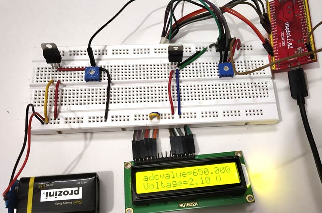
In this tutorial we convert the analog input voltage (0 to 3.3V) into digital value by using ADC in LPC2148 and display the analog voltage on LCD display (16x2). A potentiometer will be used to vary the input analog voltage.
To know more about interfacing LCD with ARM7-LPC2148 4-bit mode follow this link.
The complete code for using ADC with ARM 7 is given at the end of this tutorial, here we are explaining few parts of it.
Steps involved in LPC2148-ADC programming
1. PINSEL register is used to select the port pin of LPC2148 and the ADC function as analog input.
PINSEL1 = 0x01000000; // Select P0.28 as AD0.1
2. Select the clock and bit accuracy for conversion by writing value to the ADxCR (ADC control register).
AD0CR = 0x00200402; //Sets ADC operation as 10-bits/11 CLK for conversion (000)
3. Start the conversion by writing the value to START bits in ADxCR.
Here I have written to 24th bit of AD0CR register.
AD0CR = AD0CR | (1<<24);
4. Now we to have check the DONE bit (31th) of corresponding ADxDRy (ADC data register) as it changes from 0 to 1. So we use while loop to constantly check if conversion is done on the 31th bit of data register.
while ( !(AD0DR1 & 0x80000000) );
5. After done bit is set to 1, conversion is successful, next we read the result from the same ADC data register AD0DR1 and store the value in a variable.
adcvalue = AD0DR1;
Next we use a formula to convert the digital value to voltage and store in a variable named voltage.
voltage = ( (adcvalue/1023.0) * 3.3 );
5. Following lines are used to display digital values (0 to 1023) after analog to digital conversion.
adc = adcvalue;
sprintf(displayadc, "adcvalue=%f", adc);
LCD_DISPLAY(displayadc);  //Display ADC value (0 to 1023)
6. Following lines are used to display input analog voltage (0 to 3.3V) after analog to digital conversion and after step 5.
LCD_SEND(0xC0);
sprintf(voltvalue, "Voltage=%.2f V  ", voltage);
LCD_DISPLAY(voltvalue);                //Display (input analog voltage)
7. Now we have to display the input voltage and digital values on the LCD display. Before that we have to initialize the LCD display and use appropriate commands for sending message to display.
Below code is used to Initialize the LCD
void LCD_INITILIZE(void)          //Function to get ready the LCD
{
IO0DIR = 0x0000FFF0; //Sets pin P0.12,P0.13,P0.14,P0.15,P0.4,P0.6 as OUTPUT
delay_ms(20);
LCD_SEND(0x02);  // Initialize lcd in 4-bit mode of operation
LCD_SEND(0x28);  // 2 lines (16X2)
LCD_SEND(0x0C);   // Display on cursor off
LCD_SEND(0x06);  // Auto increment cursor
LCD_SEND(0x01);   // Display clear
LCD_SEND(0x80);  // First line first position
}
Below code is used to Display the values on LCD
void LCD_DISPLAY (char* msg) //Function to print the characters sent one by one
{
uint8_t i=0;
while(msg[i]!=0)
{
IO0PIN = ( (IO0PIN & 0xFFFF00FF) | ((msg[i] & 0xF0)<<8) ); //Sends Upper nibble
IO0SET = 0x00000050; //RS HIGH & ENABLE HIGH to print data
IO0CLR = 0x00000020; //RW LOW Write mode
delay_ms(2);
IO0CLR = 0x00000040; // EN = 0, RS and RW unchanged(i.e. RS = 1, RW = 0)
delay_ms(5);
IO0PIN = ( (IO0PIN & 0xFFFF00FF) | ((msg[i] & 0x0F)<<12) ); //Sends Lower nibble
IO0SET = 0x00000050; //RS & EN HIGH
IO0CLR = 0x00000020;
delay_ms(2);
IO0CLR = 0x00000040;
delay_ms(5);
i++;
}
}
Below function is used to create delay
void delay_ms(uint16_t j)  // Function for making delay in milliseconds
{
    uint16_t x,i;
for(i=0;i<j;i++)
{
    for(x=0; x<6000; x++);    // Forloop to generate 1 millisecond delay with Cclk = 60MHz
}
}
Complete code with demonstration Video is given below.
Complete Project Code
//Using ADC in ARM7-LPC2148
//Circuit Digest

#include <lpc214x.h>
#include <stdint.h>
#include <stdio.h>
#include <string.h>

void delay_ms(uint16_t j)  // Function for making delay in milliseconds
{
    uint16_t x,i;
for(i=0;i<j;i++)
{
    for(x=0; x<6000; x++);    // Forloop to generate 1 millisecond delay with Cclk = 60MHz
}
}

void LCD_SEND(char command)     //Function to send hex commands
{
IO0PIN = ( (IO0PIN & 0xFFFF00FF) | ((command & 0xF0)<<8) ); //Send upper nibble of command
IO0SET = 0x00000040; //Making Enable HIGH
IO0CLR = 0x00000030; //Making RS & RW LOW
delay_ms(5);
IO0CLR = 0x00000040; //Makeing Enable LOW
delay_ms(5);
IO0PIN = ( (IO0PIN & 0xFFFF00FF) | ((command & 0x0F)<<12) ); //Send Lower nibble of command
IO0SET = 0x00000040;  //ENABLE HIGH
IO0CLR = 0x00000030;  //RS & RW LOW
delay_ms(5);
IO0CLR = 0x00000040;  //ENABLE LOW
delay_ms(5);
}

void LCD_INITILIZE(void)          //Function to get ready the LCD
{
IO0DIR = 0x0000FFF0; //Sets pin P0.12,P0.13,P0.14,P0.15,P0.4,P0.6 as OUTPUT
delay_ms(20);
LCD_SEND(0x02);  // Initialize lcd in 4-bit mode of operation
LCD_SEND(0x28);  // 2 lines (16X2)
LCD_SEND(0x0C);   // Display on cursor off
LCD_SEND(0x06);  // Auto increment cursor
LCD_SEND(0x01);   // Display clear
LCD_SEND(0x80);  // First line first position
}

void LCD_DISPLAY (char* msg)         //Function to print the characters sent one by one
{
uint8_t i=0;
while(msg[i]!=0)
{
IO0PIN = ( (IO0PIN & 0xFFFF00FF) | ((msg[i] & 0xF0)<<8) ); //Sends Upper nibble
IO0SET = 0x00000050;  //RS HIGH & ENABLE HIGH to print data
IO0CLR = 0x00000020;  //RW LOW Write mode
delay_ms(2);
IO0CLR = 0x00000040; // EN = 0, RS and RW unchanged(i.e. RS = 1, RW = 0)
delay_ms(5);
IO0PIN = ( (IO0PIN & 0xFFFF00FF) | ((msg[i] & 0x0F)<<12) ); //Sends Lower nibble
IO0SET = 0x00000050; //RS & EN HIGH
IO0CLR = 0x00000020;
delay_ms(2);
IO0CLR = 0x00000040;
delay_ms(5);
i++;
}
}

int main(void)
{
  LCD_INITILIZE();        //Calls function to get ready the LCD to display
uint32_t adcvalue;
char displayadc[18];
float adc;
float voltage;
char voltvalue[18];
  LCD_DISPLAY("CIRCUIT DIGEST");
delay_ms(900);
LCD_SEND(0xC0);
LCD_DISPLAY("ADC WITH LPC2148");
delay_ms(900);
PINSEL1 = 0x01000000; // Select P0.28 as AD0.1
AD0CR = 0x00200402;  //Sets ADC operation as 10-bits/11 CLK for conversion
while(1)                                //while loop that excecutes continueously
{
AD0CR = AD0CR | (1<<24); // Starts Conversion
while ( !(AD0DR1 & 0x80000000) ); // Waits for DONE
adcvalue = AD0DR1;
adcvalue = (adcvalue>>6);             //Right Shift six bits
adcvalue = (adcvalue & 0x000003FF);
LCD_SEND(0x80);
adc = adcvalue;
sprintf(displayadc, "adcvalue=%f", adc);
LCD_DISPLAY(displayadc);             //Display ADC value (0 to 1023)
voltage = ( (adcvalue/1023.0) * 3.3 ); // formula to convert ADC value into voltage
LCD_SEND(0xC0);
sprintf(voltvalue, "Voltage=%.2f V  ", voltage);
LCD_DISPLAY(voltvalue);                //Display (input analog voltage)
memset(voltvalue, 0, 18);
memset(displayadc,0, 18);
}
}
Comments
Please show your simulation image, then i can tell you why error is coming
What can I do for this.
Can anyone help me
yes, I have attached my screenshot of Proteus simulation.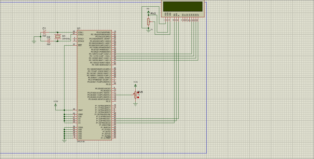
Or How can I change the pin to P 0.30(ADC0.3)..
Anyone can clear my doubt that (why should we do 6 bit rightshift and why should we do AND logical with result -->adcvalue = (adcvalue & 0x000003FF))
This is my simulation. The LCD does not display anything. What could be its problem and suggested solution? 

Done bit line is not working, while doing simulation in Proteus.
I am using KEIL Version 4, It shouldn't shows any error.