

We are living in the era of 5G and 5G-enabled devices; however, old technologies like the walkie-talkie system and RF communication system are still paramount in scenarios where a remote, short distance, cheap, and low-cost communication is required. For example, if you have a building or heavy-weight bearing construction company, then your workers need to communicate with each other for co-ordinated working. With the help of a walkie-talkie, they can communicate with each other and spread short massage or instructions by just pressing the “PTT” button to transmit voice for other workers, for them to listen and follow the instruction. Another application could be in the smart helmets to communicate among a pack of riders during a long drive, the suggested model here can communicate among six people at a time. If you want to check out other types of short-range wireless audio transmission projects, visit the IR Based Wireless Audio Transmitter and Li-Fi Audio Transmitter project using the links.
Walkie Talkie using nRF24L01 RF Module
The main component of this project is the NRF24L01 RF module and Arduino Uno which is the brain or processor. We have already learned how to interface Nrf24L01 with Arduino by controlling a servo motor remotely. For this project, the NRF24L01 RF module is chosen because it has several advantages over a digital communication medium. It has 2.4 GHz very high-frequency ISM band and the data rate can be 250kbps, 1Mbps, 2 Mbps. It has 125 possible channels in between 1Mhz spacing so the module can use 125 different channels which makes it possible to have a network of 125 independently working modems in one place.
Most importantly, NRF24L01 signals don’t overlap or cross interface with other walkie-talkie systems like police walkie-talkie and railway walkie-talkie and it does not disturb other walkie-talkies. A single nrf24l01 module can communicate up with the other 6 nrf24l01 modules at a time when they are in the receiving state. Also, it is a low power consumption module which is an added advantage. There are two types of NRF24L01 modules that are widely available and commonly used, one is NRF24L01+ and another is NRF24L01+PA+LNA (shown below) with built-in antenna.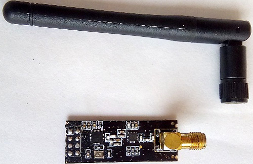
The NRF24L01+ has an onboard antenna and only a 100 meters range. It is good only for indoor use and is not suitable for outdoor long-distance communications. Moreover, if there is a wall present in between transmitter and receiver, the signal transmission is very poor. The NRF24L01 +PA+LNA with an external antenna has a PA that boosts the power of the signal before the transmission. LNA stands for Low Noise Amplifier. It is clear, filters out the noise and boosts the extremely weak and uncertain low level of the signal received from the antenna. It helps in making useful levels of signal and it has 2dB external antenna through which it can transmit 1000 meters of on-air range coverage, so it is perfect for our outdoor walkie-talkie communication projects.
Component Required for Arduino based Walkie Talkie
- NRF24L01 +PA+LNA with external 2DB antenna (2 pcs)
- Arduino UNO or any version of Arduino
- Audio amplifier (2pcs)
- Microphone circuit: You can make it yourself (discussed later) or purchase a sound sensor module.
- DC to DC step-up booster module (2pcs)
- 3.3V AMS1117 voltage regulator module
- Power indicator LED (2pcs)
- 470 ohms resistance (2pcs)
- A 4-inch loudspeaker (2pcs)
- push button (for PTT button)
- 104 PF for making of PTT button (2pcs)
- 100 NF capacitor for NRF24L01 (2pcs)
- 1k resistance for PTT button (2pcs)
- 2 sets of li-ion battery
- Li-ion battery charging and battery protection module (2pcs)
- Some jumper wire, male header pin, dotted vero board
Arduino Walkie Talkie Circuit Diagram
The complete circuit diagram for the Arduino Walkie Talkie is shown in the image below. The circuit diagram shows all the connections including the PTT button, microphone circuit, and stereo audio output.

Important: The NRF24L01 module voltage input range is 1.9v to a maximum of 3.6 volts and for voltage and current stability you have to use a 100nf capacitor into the +VCC and - GND, yet other pins of nrf24l01 module can tolerate 5-volt signal levels.
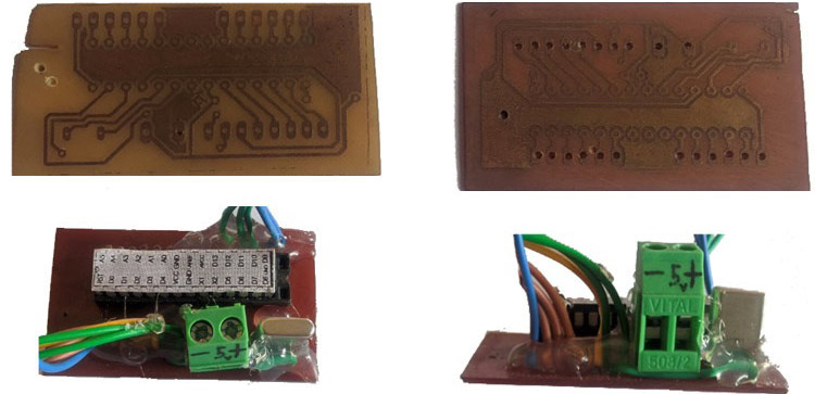
Step 1: I started with making homemade custom PCB and Arduino Atmega328p board. I had put the IC Atmega328p on the programmer and flashed it and then uploaded the code. Then, I added 16 MHz crystal on Atmega328p IC on (PB6, PB7) pin 9 and 10. The pictures of my custom made PCB and the assembled board with programmed IC is shown below.
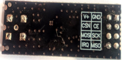
Step 2: I connected NRF24L01 modules as shown in the circuit diagram in the following order. CE to digital pin number 7, CSN to pin number 8, SCK to digital pin 13, MOSI to digital pin 11, MISO to digital pin 12 and IRQ to digital pin 2.
For the power supply, you need to drop the voltage first from 5 volts to 3.3v with good current stability. Also, you have to put a 100nF capacitor on the VCC and ground of the nrf24l01 module. So, I used AMS1117 which is a 3.3-volt voltage regulator, the module also reduces your project size and makes it compact.
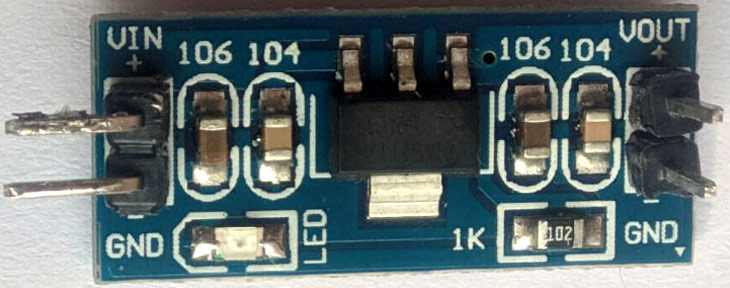
If you want to make this voltage regulator board yourself, you can buy only 3.3-volt regulator IC and can make it by adding some caps, resistance in input and output as it is very important for your RF module because it is a sensitive device. Or you can use the LM317 variable voltage regulator to build a 3.3V Regulated circuit as we did in the Breadboard power supply project.
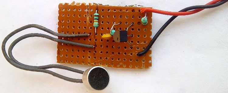
Step 3: You can purchase a sound sensor or make a simple microphone circuit as shown in the circuit diagram. It consists of only one transistor- 2n3904 NPN transistor. The below image shows the homemade microphone circuit built on a Vero board. You can also check this simple audio pre-amplifier circuit for more information.
For better understanding, I have made another representation of the whole connection with component values as you can see below

Step 4: For, making a connection from your microcontroller digital pin number 9 & 10 to your audio amplifier, I have used the PAM8403 stereo audio amplifier because by default the Arduino audio output is very low (usually you can only hear sound using just headphone, not a loudspeaker, so we need an amplification stage). The module can drive two laptop speakers easily and is available at a very low cost. Also, it comes with a very powerful audio amplifier in an SMD package which requires very little space. The PAM8403 audio amplifier module is shown below.
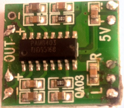
The connection is very simple, a 3.7V to 5V power supply is required to power the Audio Amplifier. The left channel and right channel audio input from Arduino pin 9 and 10 along with the ground pin should be given as input for this amplifier module as shown in the circuit diagram. In my case, I have used a single 4 inch 8 ohms speaker and only used right channel output. If you want, you can use two speakers with this module.
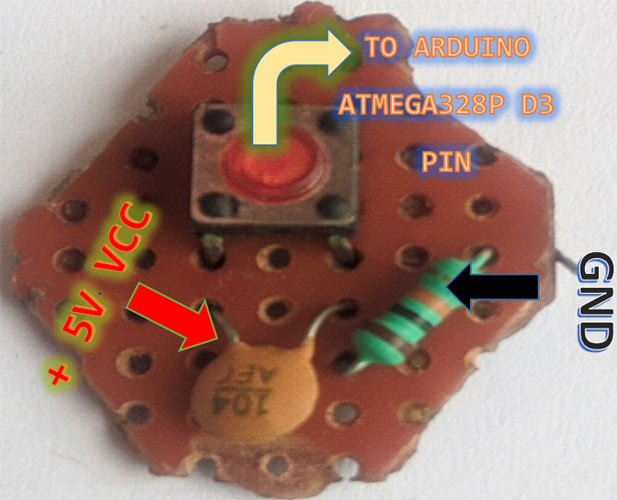
Step 5: Next, I built the PTT switch using a simple push-button. I added a 104PF or 0.1uf capacitor to prevent switch bouncing or erratic signals when the switch is pressed. Pin 4 is now directly connected with Arduino Digital pin D3 as an interrupted pin is assigned to the coding.
The NRF24L01 + PA+LNA when transmitting an audio signal or DATA packets consumes more power hence, it consumes more current. When you press the PTT button suddenly, the power consumption increases. For handling this suddenly increased load, you must use a 100nF capacitor on +vcc and Ground for the transmission stability of the NRF24L01+PA+LNA Module.
When the switch is pressed, the Arduino board receives an Arduino Interrupt on its pin D3. In the program, we will declare the digital pin 3 of Arduino constantly checking its input voltage. If the input voltage is low, it keeps the walkie-talkie in receiving mode and if the digital pin number 3 is high, it switches the walkie-talkie into transmitting mode for sending voice signal picked up by the microphone process through microcontroller and transmit through NRF24L01+PA+LNA with an external antenna.
Step 6: For the power supply, I have chosen this Li-ion battery. To power, all the components like Arduino IC Atmega328p, NRF24L01+PA+LNA, audio amplifier, PTT button, and Microphone circuit, I used 2 sets of Li-ion battery for this project as shown below.
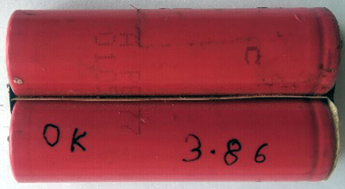
A good cell has a voltage level 3.8v to 4.2 volts and the charging voltage is 4v to 4.2 volts only. To know more about lithium batteries you can check the linked article. These batteries are very popularly used in portable electronic devices and electric vehicles. But Li-ion battery cells are not as robust as other batteries, they need protection from being overcharged and discharged too fast, meaning the charging/discharging current and voltage should be maintained within safe limits. Therefore, I used the most propeller Li-ion battery charging module - TP4056. We have previously used this module for building a Portable Power Bank, you can check out that for more details on this board.
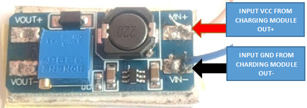
Step 7: I have used a 2 Amp dc to dc step up booster module because Arduino atmega328p, Audio Amplifier, microphone circuit, PTT button everything needs 5 volt but my battery can only supply 3.7V to 4.2V, So I need a boost converter to reach 5V with more than 1 Amp of stable power output.
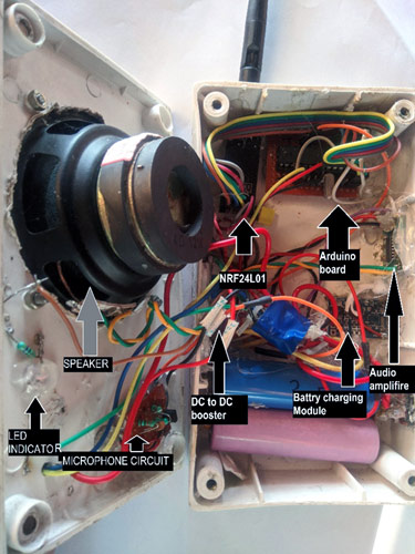
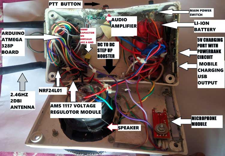
After you have built the circuit, you can assemble it in a small enclosure. I used a plastic box and placed my circuits as shown in the image below
Walkie Talkie Arduino Code
The complete program for your Arduino walkie talkie can be found at the bottom of this page. In this section, let's discuss how the program works. Before getting there, you need to include some Libraries which are listed below.
Begin the programming by including the Radio and Audio Library headers as shown below
#include <RF24.h>
#include <SPI.h>
#include <RF24Audio.h>
#include "printf.h"    // General includes for radio and audio lib
Initialize the RF Radio on pins 7 and 8 and set up the audio radio number to 0. Also, initialize the ppt button on pin 3.
RF24 radio(7,8);    // Set radio up using pins 7 (CE) 8 (CS)
RF24Audio rfAudio(radio,0); // Set up the audio using the radio, and set to radio number 0
int talkButton = 3;
Inside the setup function, begin serial monitor at 115200 baudrate for debugging. Then initialize the ppt button connect to pin 3 as an interrupt pin.
void setup() {
  Serial.begin(115200);
  printf_begin();
  radio.begin();
  radio.printDetails();
  rfAudio.begin();
  pinMode(talkButton, INPUT);//sets interrupt to check for button talk abutton press
  attachInterrupt(digitalPinToInterrupt(talkButton), talk, CHANGE);  //sets the default state for each module to receive
  rfAudio.receive();
}
Next, we have a function called talk() which is called in response to interrupt. The program checks the state of the button if the button is pressed and held it enters transmit mode to send the audio. If the button is released it enters receive mode.
void talk()
{
  if (digitalRead(talkButton)) rfAudio.transmit();
  else rfAudio.receive();
}
void loop()
{
}
The complete working of this project can be found in the video linked below. The Walkie Talkie produces some noise during operation, this is the noise from the carrier frequency of the nRF24L01 Module. It can be reduced by using a good sound sensor or microphone module. If you have any questions about this project you can leave them in the comment section below. You can also use our forums for getting quick answers to your other technical queries.
Complete Project Code
#include <RF24.h>
#include <SPI.h>
#include <RF24Audio.h>
#include "printf.h"    // General includes for radio and audio lib
RF24 radio(7,8);    // Set radio up using pins 7 (CE) 8 (CS)
RF24Audio rfAudio(radio,0); // Set up the audio using the radio, and set to radio number 0
int talkButton = 3;
void setup() {
  Serial.begin(115200);
  printf_begin();
  radio.begin();
  radio.printDetails();
  rfAudio.begin();
  pinMode(talkButton, INPUT);
  //sets interrupt to check for button talk abutton press
  attachInterrupt(digitalPinToInterrupt(talkButton), talk, CHANGE);
  //sets the default state for each module to receiver
  rfAudio.receive();
}
//void talk()
//Called in response to interrupt. Checks the state of the button.
//If the button is pressed (and held) enters transmit mode to send
//audio. If button is release, enters receive mode to listen.
void talk()
{
  if (digitalRead(talkButton)) rfAudio.transmit();
  else rfAudio.receive();
}
void loop()
{
}
Comments
Hi
Hope you are well,
I have figured out why my circuit wasn't functioning properly. I currently am using the NRF24L01 module as the transceiver for both circuits. With further research I discovered that the NRF24L01+PA+LNA module has the interrupt pin (IRQ) which allows you to switch from receiving mode to transmitting mode. I have ordered the NRF24L01+PA+LNA yesterday and should arrive within the week I'll keep you updated as I make progress.
Regards
Hello
Thanks for the tip, I am using the nfr24l01 and managed to send and receive voice, but I use the minimal example found in the rf24Audio library, the sound is sent and received without latency, but at the same time a frying sound appears
Hi
I'll try again with NRF24L01, perhaps the frying sound is due to intereference between the two circuits try distancing them further? Thanks for the tip!
Regards
Hi,
Sorry I'm asking this question, but PAM8403 is stereo amplifier, with 2 chanels. Why not to use one chanel for speaker and second one for mic? Are there any issue with it?
Why would you use a stereo amplifier when you're using only one ouput channel? There is only one input from the microphone as well!
You could instead use a mono amplifier.
Also, am asking out of curiousity... was using the 0.1uF capacitor enough to handle debouncing? Did you not have to check for debounce in code?
Cheers,
Jay
Why Input/Microphone analog pin go to A1, it should be go to A0 !
BR
Nice project!
What chip would you recommend if I want to get 5Km or even 10Km coverage?
for long range communication you can use LORA module
If so, how? How should the code be changed? Best regard.
This code will not work for LORA module..you have to read tutorials for LORA module. you can follow below tutorials which are available on Circuit digest website.
https://circuitdigest.com/microcontroller-projects/arduino-lora-sx1278-…; (here you can see interfacig of Lora with arduino)
https://circuitdigest.com/article/introduction-to-lora-and-lorawan-what…
https://circuitdigest.com/microcontroller-projects/interfacing-sx1278-l…
salut les amie qui peut me donne un bon diagramme d,un interphone merci
Hi! I was just wondering how the code would need to modified if I only want one way communication - i.e. there would be one transmitter and one receiver.
Any advice would be appreciated, thanks!
I am not able to send and receive voice please
Hello, I am trying to do this in home but I am still a student and I am not that experienced in this kind of circuits and I was wondering if I need 2 Arduinos for both Walkie Talkies or you can make only one and make it work with other Walkie Talkies?
Hi , I have been test your code , but it doesn't work , and I realized that your code is wrong.
Please fix this code !
Thanks, by

Hi,
I am trying to replicate the walkie talkie and I ran into some problems, I am using the Kemo Electronic Amplifier 1 W, do I have to connect it to a separate power supply because it's consumption is around 380 mA? Also, when I press the button it doesn't seem to respond, do you have any suggestions?
Regards