

The features of digital products are growing enormously, which triggers the frequent usage of smartphones in several applications. Thus, the battery backup time is decreasing. It will be fun to build a Power Bank for a Mobile Phone as a spare charging source for emergency purposes, which is also portable. In this article, we will discover how to make a power bank with a super-simple power bank circuit diagram.
The important factor to be considered while working with lithium batteries is the protection circuits and the quality of the batteries. But, when this comes to 18650 cells, the risk factor is less compared with pouch batteries. Good protection is offered by a few readymade modules available in the market. When working with lithium batteries, safety is paramount. While pouch batteries require extensive protection circuits, 18650 cells are inherently safer and work well with readily available power bank charging modules.
Table of Contents
- Components Required
- Power Bank Circuit Quick Reference
- Circuit Diagram and Working Principle
- └ Charging Mode Operation
- └ Discharge Mode (Phone charging)
- TP4056 Charging Module with Protection Circuit
- └ Built-in Protection Circuit Components
- 3V to 5V Boost Converter Module
- └ Technical Specifications
- Charging the Power Bank Circuit
- Charging the Mobile Phone with this Power Bank
- Troubleshooting
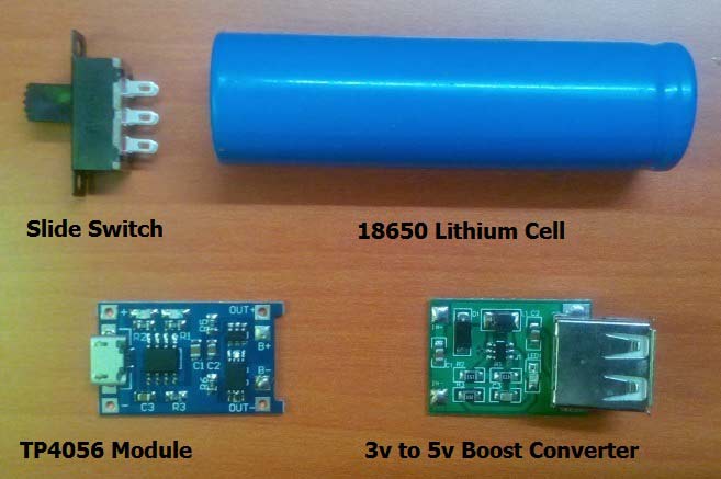
Components Required for DIY Power Bank Circuit
Building a reliable power bank circuit board requires specific components that work together to charge, protect, and deliver power safely.
- 18650 Lithium cell
- TP4056 Module with battery protection circuit
- 3V to 5V boost converter with 1A current control
- Slide switch
Power Bank Circuit Quick Reference
| Specification | Details |
| Battery Type | 18650 Lithium-ion Cell (3.7V) |
| Output Voltage | 5V DC (USB Standard) |
| Output Current | Up to 1A |
| Charging Method | CC-CV (Constant Current - Constant Voltage) |
| Protection Features | Overcharge, Over-discharge, Overcurrent |
| Efficiency | Up to 92% |
Power Bank Circuit Diagram and Working Principle
Below is the circuit diagram for our power bank. As we can see, it's fairly easy to make a power bank with a Li-ion battery, TP4056 module and a boost converter. The power bank circuit diagram below illustrates the complete connection scheme. This simple yet effective design combines a power bank charging module (TP4056) with a boost converter to create a functional mobile charging solution.

There are two modes of operation for the circuit:
Charging Mode Operation
- Input power is connected to the TP4056 power bank charging circuit through Micro USB
- The module uses the CC-CV charging protocol for lithium-ion batteries
- Built-in protection mechanism stops the charge at 4.2 volts
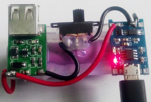
- The red LED will indicate that charging is taking place
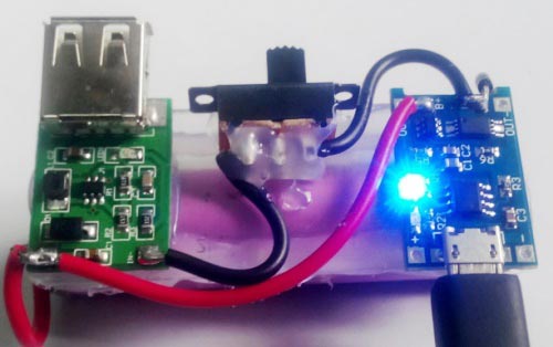
- The blue LED will come on when the battery is fully charged
Discharge Mode (Phone charging)
- The toggle switch will activate the boost converter circuit
- The 5V power bank module will convert the 3.7 volts to standard 5 volts in a USB outlet
- Over-discharge protection will not allow the battery to discharge if the battery reaches 2.4 volts.
- Current is limited to be short-circuit safe
18650 Lithium Cell:
The 18650 lithium cell is an important part of this power bank circuit. The term 18650 cell is due to the cell dimension, it is cylindrical in shape with a 18mm diameter and a height of 65mm. Also, these cells are available in different capacities corresponding to applications. These rechargeable cells are widely used in power bank circuit boards due to their reliability and safety features. They are rechargeable cells with 3.7V output.
The method of charging a single lithium-ion cell requires two processes.
- Constant current (CC)
- Constant voltage (CV)
During CC, the charger should supply constant current with increasing voltage till the voltage limit. Next, a voltage equal to the maximum limit of the cell should be applied, during which the current declines steadily to the lower threshold current (i.e., 3% of the constant current). All these operation is carried out by the TP4056 module, which is a highly reliable and affordable choice. The power bank charging module supplies a fixed current (typically 1A) while the voltage gradually increases from 3.0V to 4.2V. The TP4056 module automatically handles both stages, making it the ideal power bank charging circuit solution.
TP4056 Charging Module with Protection Circuit
This is a low-cost charging solution to charge any type of single lithium-ion battery. Mobile batteries, 18650 NMC cells, Lithium pouch batteries, etc. The micro B Receptacle and easy adjustable 1A output current control make it a reliable choice to charge any low-capacity batteries. It can be connected to any wall socket-based mobile charger or any sort of USB to micro B cable. It is made of an integrated PMOS load switch architecture, hence reducing the overall additional components. The TP4056 is a complete, cost-effective power bank charging module designed for single-cell lithium-ion batteries. It's widely used in DIY power bank circuits because it integrates charging control, protection features, and visual indicators in a compact package.
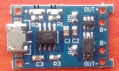
The module also has two indications: a Red colour LED (L1) to indicate the ongoing charging condition. Blue colour LED (L2) indicates the completion of charging. This module can operate at high ambient temperature since the thermal feedback can regulate the charge current. The charge voltage is 4.2V, and the current can be adjusted by changing a resistor in the module. But the default current will be 1A when bought.
Built-in Protection Circuit Components
The protection circuit is critical for safe power bank circuit board operation. The protection circuit includes,
1. DW01x – Single-cell lithium-ion battery protection IC with dual MOSFET control feature. Below is an application test circuit provided in the datasheet.
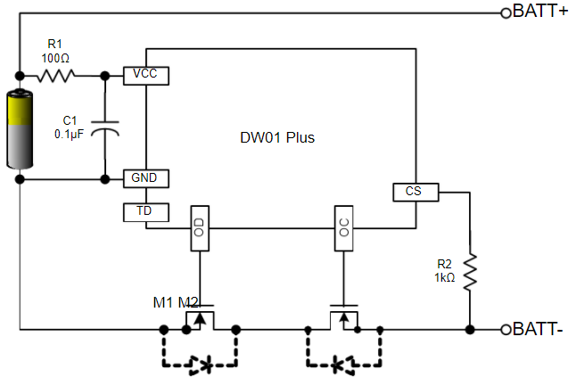
2. FS8205A – Dual N-Channel enhancement MOSFET with common drain connection. Also, the drain to source resistance is low. The gate of the MOSFET is controlled through the DW01A IC.
Thus, the DW01A provides Overcharge control, overdischarge control, and Overcurrent control by controlling the MOSFET through the circuit.
3V to 5V Boost Converter Module
A lithium battery only provides 3.7 volts here, but we need 5v to charge the Cellphone, so we have used a 3-volt to 5v boost converter module here. This boost converter module has a high efficiency of up to 92% and integrated overcurrent protection. The topology used inside is a Non-isolated step-up converter which operates at a switch frequency of 1MHz. The overall power output that can be drawn out of this module is 5W. The output voltage can be adjusted to 12V by changing a resistor in the module, but the maximum current will be 400mA. But by default, this module is available at a rating of 5V, 1A. Under this rating, the output ripple is 20mV pk-pk. The module also has a USB Type-A female receptacle, which is universal. Any USB power cable can be used as an interface. The operating temperature of the module is -40°C to +85°C. It also has an LED indication to indicate the presence of a supply from a battery source. The Red colour LED indicates the presence of a power supply across the terminals. This 5V power bank module efficiently steps up the voltage to meet USB power delivery standards.

Boost Converter Technical Specifications
| Parameter | Specification |
| Input Voltage Range | 2.5V - 5V |
| Output Voltage | 5V ±5% (adjustable to 12V) |
| Output Current | 1A maximum (at 5V output) |
| Maximum Power Output | 5W |
| Conversion Efficiency | Up to 92% |
| Switching Frequency | 1MHz |
| Output Ripple | 20mV peak-to-peak |
| Operating Temperature | -40°C to +85°C |
We previously used the same module in Solar Mobile Phone Charger Circuit.
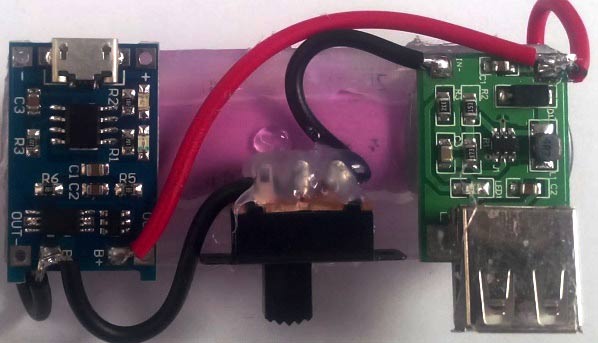
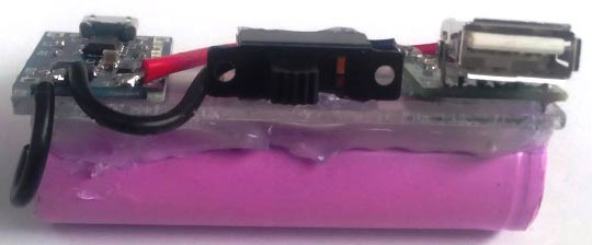
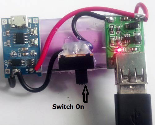
The modules were connected and fixed to a plastic plate using hot glue.
Charging the Power Bank Circuit:
Once assembled, your power bank circuit needs to be charged before first use. The TP4056 power bank charging module provides clear visual feedback throughout the charging process.
The red colour LED indicates the battery is charging in this power bank circuit.
Blue colour LED indicates the charge is complete.
Charging the Mobile Phone with this Power Bank:
The DIY power bank for mobile phone charging is now ready to provide emergency power. The 5V power bank module delivers standard USB power compatible with all smartphones.
1. Connect the USB to micro B cable to the output of the boost converter.
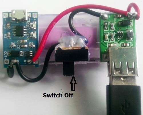
2. Turn the slide switch ON.
3. The mobile phone's battery starts to charge from the power bank
So this is how you can easily make a Power Bank Circuit for charging your smartphones. Below you can find the video which demonstrates how to build a 18650 Lithium Cell-based power bank circuit.
Troubleshooting Common Power Bank Circuit Issues
| Problem | Possible Cause | Solution |
| No LED illumination | Incorrect wiring or dead charger | Check all connections, verify polarity, test with different USB charger |
| LED flashing | Battery deeply discharged or faulty | Leave connected for 30 minutes; if persists, replace battery |
| Blue LED always on | Battery not connected or bad connection | Verify battery connections to B+ and B- terminals |
| No output voltage | Switch off or loose connections | Verify switch position, check boost converter input connections |
| Low output voltage (<4.5V) | Battery depleted or boost converter issue | Recharge power bank; test boost converter with fresh battery |
| Intermittent charging | Loose USB cable or poor solder joints | Try different cable; re-solder all connections |
Conclusion:
Creating a DIY power bank circuit is a unique way to gain experience in practical electronics and battery management systems. It is possible to use inexpensive and simple modules - the TP4056 power bank charging module and a 5V power bank module (boost converter) - together with a 18650 lithium cell to create a power bank for charging mobile phones.
The power bank circuit diagrams included in these projects depict typical protection features (such as overcharge, overdischarge, and overcurrent) commonly found in commercial power banks. While power banks can be more convenient and aesthetically pleasing than designing your own circuit, they will not teach you about battery charging applications, nor are they as satisfying as your own DIY power bank circuit board. Using the above projects, a power bank circuit board can also be a valuable source of education, functionality, and appearance.
You may require a portable backup source of power, want to learn about charging circuits, or plan to alter the circuit design for special applications, such as a 12V power bank module, and you can acquire a reliable understanding of portable charging circuits from here.
Frequently Asked Questions on the Power Bank Circuit
⇥ Q1: What is the reason for the power bank circuit? I'm using a boost converter?
A boost converter is necessary because 18650 batteries are 3.7V, and smartphones have a charging voltage of 5V as defined in USB specifications. The boost converter module increases the voltage input from 3.7V and outputs a charge of 5V with a nominal efficiency of around 92%; therefore, the phone can receive an acceptable charge.
⇥ Q2: How many times can I charge my phone with a 2500mAh Power Bank?
A 2500mAh power bank can initially charge a 3000mAh phone battery to approximately 60-70% before depleting. The actual performance can vary since you'll lose approximately 10-15% of the accumulated energy due to conversion losses, and battery health is also important. You may want to utilise a 18650 cell capacity of 3500mAh or more to charge a phone battery completely.
⇥ Q3: Can I safely build a DIY power bank circuit at home?
Yes, building a power bank circuit at home is completely safe, assuming you are using the correct protection circuits. The TP4056 type modules include a DW01 protection IC and a FS8205A MOSFET switch, which prevents overcharge, overdischarge, and short-circuit conditions. It's important to always use genuine 18650 batteries, check polarity prior to usage, and avoid shorting protection implemented in the protection circuits.
⇥ Q4: What do the red and blue LED lights on the TP4056 charging module mean?
The red LED indicates that the active battery is charging (constant voltage and constant current stage). The blue LED illuminates when charging is complete (battery voltage reaches 4.2V and when charge current drops below ~3% threshold), indicating the power bank is fully charged and ready to use!
⇥ Q5: Can you make a 12V power bank with this circuit?
You do have the ability to adjust the feedback resistor for the boost converter to get 12V out, but the output current is reduced to approximately 400mA. The circuit is usable for LED strips, routers, and other devices that are low-powered and require a 12V supply, but not for high-current applications.
⇥ Q6: How efficient is this diy power bank circuit?
The boost converter is efficient at ~92%. The total efficiency with charging losses included is approximately 85-90%. This means if you have a 2500mAh battery (3.7V = 9.25Wh), you would expect to output ~1850-2250mAh at 5V to your phone.
⇥ Q7: How can I tell when to recharge my power bank battery?
When the battery has low voltage = undervoltage (less than 2.5 - 3V), the boost converter's red LED will fade or turn off. Your phone will either slow down or cease charging altogether. To avoid over-discharge damage to a lithium battery, you should charge it when the performance drops. You can also add a battery voltage indication module to your battery pack for a more accurate indication.
Related Power Supply Circuit Projects
Explore more DIY circuits that focus on compact energy storage and efficient charging designs. These projects demonstrate different approaches to creating reliable portable power solutions using various battery types.

The market for power banks has exploded, making it one of the most popular electronic products available. Fortunately, we will go over a step-by-step approach in this post on how to make a Rechargeable Power Bank (4500mAh) using 3.7V DC Batteries at Home.

For this Power bank, we have designed a PCB layout and schematics by using the online website EasyEDA. You can find all the PCB layouts, schematics and Gerber files in the description below.

Today, we are going to build a charger circuit for charging a Ni-Cd Battery. The Fast charging requires a proper shutdown after a full charge. Unlike a lead-acid battery or a lithium battery, a Ni-Cd battery cannot take up a float charge.
Comments
To increase capacity number of lithium cells can be increased in parallel.
When using the same module arrangement the charging time increases
equally to the capacity, Eg: 10000mAh takes about 10 hours to charge from
empty to full. But, there is no other problem in using in that way. Ensure the
cells that are connected in parallel are of same capacity (For eg : 3.6V, 2200mAh).
So there is no need to be worried about balance charging? and where would we be able to connect a higher input voltage if the batteries allowed for it, or would we just create a whole new circuit leading to the positive and negative ends of the batteries in parallel in order to charge at a higher voltage?
how much time does it take to charge cell phone>?
how can I increase the current to 2A?
I don't think increasing the current is an easy task here. You will need major modifications
What about connecting 2 (or more) TP4056 in parallel? Of course, thinking in a power source wich can handle, say, 2A (or more)... Could it work?
This module is designed to charge a 18650 cell whose full charge voltage is 4.2V. Also the charging current of these cells are rated less than 1A. So why do you need a 2A charger? A charging current of 2A or more could easily kill a 18650 cell..
The idea of using two modules in parallel might actually work though
Anyway you can give me a website i could purchase the parts from?
this circuit does not have an over-discharge protection? because the booster is fixed to the battery, hence the TP4056A can't prevent over-discharge?
This circuit does have a over-discharge protection.
The booster is connected to the output of the TP4056A module. If the booster drains too much current from the battery the TP4056 will prevent it from doing so.
There is no over-discharge protection. The booster is connected in parallel to the battery and TP4056, thus even if the TP module was powered on it would have no control over the discharge from the booster. To fix this you need a discharge protection IC in series with the booster and battery.
Can we use old mobile battery/s in place of 18650 cell
Good idea and it would most likely work I guess. Why not give it a try!!
which type of battery used protected/unprotected lithium celll????
The battery used here 18650 lithium cells.. and they do not come with protection circuit
My power bank is crashed when i connect the bettery terminal on the circuit board the blue light begins to gow with a sound "geeeeeeeeeeeeeeee............"
Can anyone tell me the design for boost converter of 19V & 3amp o/p
The circuit you give is different from the PCB. On the circuit you have the switch between the 2 pluses, on the PCB you have it between the 2 minuses. You do not give good explanations how to connect the switch and you do not show the connections well on the PCB pictures.
The switch is used only to break or make the connection. It can either be present on the positive rail or on the negative rail. However having it on the negative rails is a bit more advantages
i don`t see a deep discharge protection. if it is the step-up booster i think it is.
It discharge your battery to almost a 0,5 volts lithium battery`s dont like that and wil posibley be dead or get dangerous after it, becouse the chemestry inside the battery wil get unstable. inside your phone te battery is monitored by a bms battery monitoring system en wil never !!!! be fulli dicharged.
so my 2 cents, get a undervoltage protection at a rc hobby shop for example.
No mike you don't have to worry about that. The charging module also has a protection feature in it. It will not allow the battery to drain below 3.2V.
Enormously the modern technology advances up to a high range, using a smartphone we can get several features.
What changes are required in boost board to give 4.5v
I have connected (3) old laptop batteries serially with tp-4056 board for charging the batteries but how to charge the mobile from the batteries what usb board to use? Ampere handling ??? Plz. help.
No you should not do it.
The TP-4056 is meant to charge only one battery at a time. If you have connected the batteries in series and then have connected to the module, then you the voltage off all the three batteries would have added up and thus damaged your module
Do you have the circuit diagram for the booster chip?
what are disadvantages increasing the number of cells for 2000 mah powerbank circuit ?
Thank you for the instructions. I made it. but the boost converter is heated when the mobile phone is charging.Is there any solution to reduce the heat. Or , does the guage of wires matter for this situation as the wires can't bear the current?
pls sir out four cell inside d power banks i add one cell to make it five i discover that d pannel is hoting
How can I make a 12V 18000mAh battery bank?? Is it possible?? And how I'll connect it to my load?? thanks
You are asking for a 12V 18Ah battery.
It can be found in your computer UPS and yes it can be used as a power bank.
If you want to make it small you should use lithium which is not a beginner friendly
When we charging the power bank battery we need to ON the switch?
How many hours it will take to charge a single 18650 battery 2000mah
It depends on the Adapter rating . If the adapter is rated for 1A that is 1000mA then it will take (2000mah/10000mA) two hours to charge it
Can we design & construct Compact Power banks for Smartphones similar to a Flash Drive?
The electrical circuit has to be further modified to achieve compactness with the Battery construction.
Thanks & Regards,
Prashant S Akerkar
Excellent tutorial. Much appreciated! Hopefully you are still checking this. I was actually in the process of making one of these when I cam across this. I had two manin questions,
#1. is the switch necessary? Is the purpose to keep from the phone battery reversing and draining into the power bank? If not, and if it cen be made without the switch is there something in the circut that is preventing the reverse draining?
#2. If I already have a protection circut on a lipo battery, is the 4056A necessary? or could I use a simple 5 pin micro usb board with no circuitry?
Thansk!
Brian Martin
the batteries are well charged and when the load charging switch is switched on , after few seconds the out put at the USB falls to zero.
This happens on ' no load ' and also 'on load ' condition.
please suggest a solution.

How can you increase the powerbank's capacity, like for example bout 10000mAh?
Would there be any changes with regards to the module used?