

Infrared is the most commonly used wireless data transfer medium for limited range, and we already covered about simple IR Transmitter and Receiver circuit. Today in this Article, we will learn how to build a Crude Wireless Audio Transfer Circuit Using IR LEDs. Using this circuit you should be able to play songs from your IPod, mobile or computer to an external speaker without having to connect them directly though an AUX cable. The circuit comes with many limitations and there are better ways like Bluetooth to play songs wirelessly, hence this article only aims to help you understand simple audio circuits and at the same time have fun building it. Also the circuit of this project is simplified as much as possible to keep things simple and reliable to make the build easier, so this should be a great weekend project to build and learn along with your friends. Now, that being said let’s get started!!
Working Principle
The principle behind the circuit is that, we will have two individual circuits. One is the transmitter circuit and the other is the receiver circuit, the transmitter circuit will be connected to the 3.5mm Audio jack for audio input and the receiver circuit will be connect to a speaker to play the songs. The Audio signal will be transmitted through an IR LED from the transmitter circuit; the IR signals will be then received by a photodiode which will be placed on the receiver circuit. The audio signal thus received by the photodiode will be very weak and hence it will be amplified by a LM386 amplifier circuit and finally played on a speaker.
It is very similar to your TV remote, when you press a button the IR led at the front of your TV, it transmits a signal which will be picked up by a photodiode (TSOP commonly) and the signal will be decoded to find which button you have pressed, check here the universal IR remote using TSOP. Similarly here the signal transmitted will be an audio signal and the receiver will be a plain photodiode. This technique will also work with normal LEDs and solar panels; you can read the Audio Transfer using Li-Fi article to understand how this method is very similar to Li-Fi technology.
Components Required
- Breadboard (2 Nos)
- IR LED (2 Nos)
- 3.5mm Audio Jack
- LM386 IC
- Photo Diode
- 100K POT
- Resistors (1k, 10k, 100k)
- Capacitors (0.1uF, 10uF, 22uF)
Circuit Diagram
The complete circuit diagram for this Wireless Music Transfer using IR LEDs project is given below:

Transmitter Circuit
The transmitter circuit only consists of a couple of IR LEDs and resistor connected directly to the audio source and the battery. One tricky place where you might encounter a problem is with connecting the audio jack to the circuit. A normal Audio jack will have three output pins two for left and right earphone and the other is shield which will act as ground. We need one signal pin which can be either left or right and one ground pin for our circuit. You can use a multimeter in connectivity to find the right pinouts. My jack has pins in this format shown below.

The working of the Transmitter circuit is pretty simple, the IR light from the IR LED acts as a carrier signal and the intensity of the IR light acts as a modulating signal. So if we power the IR led through an Audio source the battery will illuminate the IR led and the intensity with which it glows will be based on the audio signal. We have used two IR LEDs here just to increase the range of the circuit; otherwise we can use even one. I build my circuit over a breadboard and the circuit can be powered anywhere between 5V to 9V, I used a regulated 5V in place of the battery so I did not use the current limiting resistor 1K. The breadboard setup is shown below, I have connected my IPod here as an audio source but can use anything that has an Audio jack (Sorry Iphone users).

Receiver Circuit
The receiver circuit consists of a photodiode which is connected to an Audio amplifier circuit. The Audio amplifier circuit is build using the popular LM386 IC from Texas instruments, the advantage of this circuit is that its minimal requirement of components. This circuit can also be powered from a voltage ranging from 5V to 12V, I have used my breadboard regulator module to supply +5V to the circuit but you can also use a 9V battery as well. My transmitter set-up on the bread board is shown below.

The pin detail of the LM386 IC is given below
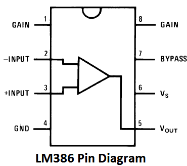
PIN 1 and 8: These are the gain control PINs, internally the gain is set to 20 but it can be increased up to 200 by using a capacitor between PIN 1 and 8. We have used 10uF capacitor C3 to get the highest gain i.e. 200. Gain can be adjusted to any value between 20 to 200 by using proper capacitor.
Pin 2 and 3: These are the input PINs for sound signals. Pin 2 is the negative input terminal, connected to the ground. Pin 3 is the positive input terminal, in which sound signal is fed to be amplified. In our circuit it is connected to the positive terminal of the condenser mic with a 100k potentiometer RV1. Potentiometer acts as volume control knob.
Pin 4 and 6: These are the power supply Pins of IC, Pin 6 for is +Vcc and Pin 4 is Ground. The circuit can be powered with voltage between 5-12v.
Pin 5: This is the output PIN, from which we get the amplified sound signal. It is connected to the speaker though a capacitor C2 to filter DC coupled noise.
Pin 7: This is the bypass terminal. It can be left open or can be grounded using a capacitor for stability
Testing your Wireless Music Transfer Circuit
Once you have built both the circuits on the breadboard, power them individually and connect the Audio source to the Transmitter part, now place the receiver circuit in line with the transmitter circuit within 10cm and check if you hear the audio through the circuit. If not try adjusting the position of POT RV1 until you hear something. The complete working of the circuit can be found at the video linked at the bottom of this page.

If the circuit worked at the first try, then consider yourself as lucky. Because there are many places where one could go wrong here, so building a Audio circuit on breadboard is most likely be susceptible to noise. So for people who dint get it working the first time, follow the steps to debug the circuit.
- After powering the Transmitter circuit, use your mobile phone camera to check if the IR LED is glowing, do this in a dark room so that you can detect it easily. In a bright room even the camera cannot pick IR light. If it glows then its assured that the transmitter is working as expected.
- After building the receiver circuit, replace the photodiode with the 3.5mm jack and play a song. The audio from your phone should be amplified and played in your speaker, if not adjust RV1 until it starts working. Once you ensure working replace the 3.5mm jack with Photodiode again.
- Proceed to this step only after following the above two. Do not expect the circuit to work for longer range, leave the transmitter at a fixed place and try positioning the receiver and different angles until it picks up the signals.
By this time, I hope you got your circuit working and enjoyed building it along the way. If not post your problems in the comment section below or use the forums instead for quick response.
