

WARNING!! The circuit diagram discussed in this project is only for educational purposes. Be advised that working with 220V AC mains voltage requires extreme precaution and safety procedures should be followed. Do not touch any of the components or wires when the circuit is in operation.
It is easy to turn on or off any home appliance by using a switch or by using some control mechanism as we did in many Arduino based Home Automation projects. But there are a lot of applications where we need to control the AC power partially, for example, to control the speed of the Fan or the intensity of a Lamp. In this case, the PWM technique is used, so here we will learn how to use Arduino generated PWM to control AC fan speed with Arduino.
In this project, we will demonstrate Arduino AC fan speed control using TRIAC. Here phase controlling method of the AC signal is used to control the AC fan speed, using PWM signals generated by Arduino. In previous tutorial, we controlled the DC fan speed using PWM.
Components Required
- Arduino UNO
- 4N25 (Zero crossing detector)
- 10k Potentiometer
- MOC3021 0pto-coupler
- (0-9)V, 500 mA Stepdown Transformer
- BT136 TRIAC
- 230 VAC Axial AC fan
- Connecting wires
- Resistors
Working of AC fan control using Arduino
The working can be divided into four different parts. They are as follows
1. Zero-Crossing Detector
2. Phase Angle Controlling circuit
3. Potentiometer to control the Fan speed amount
4. PWM signal Generation circuit
1. Zero-Crossing Detector
The AC supply we get in our household is 220v AC RMS, 50 HZ. This AC signal is alternating in nature and changes its polarity periodically. In the first half of every cycle, it flows in one direction reaching a peak voltage and then decreases down to zero. Then in the next half-cycle, it flows in alternate direction (negative) to a peak voltage and then again comes to zero. For controlling the speed of AC Fan, the peak voltage of both the half cycles needs to be chopped or controlled. For this, we must need to detect the zero point from which the signal is to be controlled/Chopped. This point on the voltage curve where the voltage changes the direction is called zero voltage crossing.
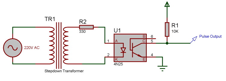
The circuit shown below is the zero crossing detector circuit which is used to get the zero-crossing point. First, the 220V AC voltage is stepped down to 9V AC using a step-down transformer and it is then fed to a 4N25 optocoupler at its pin 1 and 2. 4N25 optocoupler has an inbuilt LED with pin 1 as anode and pin 2 as a cathode. So as per the circuit below, when the AC wave goes closer to the zero-crossing point, the inbuilt LED of 4N25 will get turned off and as a result, the output transistor of 4N25 will also get turned OFF and the output pulse pin will get pulled up to 5V. Similarly, when the signal increases gradually to the peak point, then the LED turns ON and the transistor will also turn ON with the ground pin connected to the output pin, which makes this pin 0V. Using this pulse, the zero-crossing point can be detected using Arduino.
2. Phase Angle controlling Circuit
After detecting the point of zero crossing, now we have to control the amount of timing for which the power will be ON and OFF. This PWM signal will decide the amount of voltage output to the AC motor, which in turn controls the speed of it. Here a BT136 TRIAC is used, which controls the AC voltage as it is a power electronic switch for controlling an AC voltage signal.
TRIAC is a three-terminal AC switch that can be triggered by a low energy signal at its gate terminal. In SCRs, it conducts in only one direction, but in the case of TRIAC, the power can be controlled in both directions. To learn more about TRIAC and SCR, follow our previous articles.
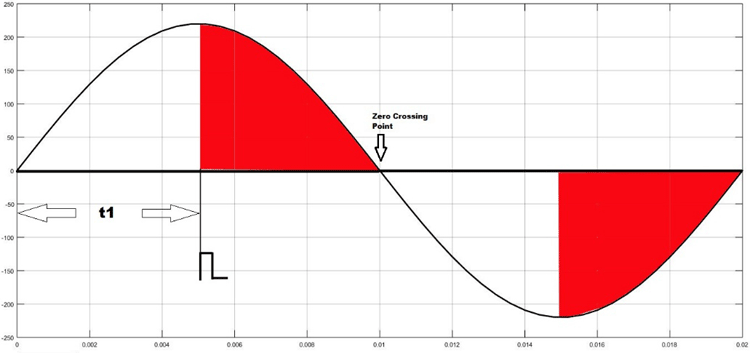
As shown in the figure above, the TRIAC is triggered at a firing angle of 90 degrees by applying a small gate pulse signal to it. The time “t1” is the delay time which is given as per the dimming requirement. For example, in this case, the firing angle is 90 percent, hence the power output will also be halved and hence the lamp will also glow with half intensity.
We know that the frequency of the AC signal is 50 Hz here. So the time period will be 1/f, which is 20ms. For a half cycle, this will be 10ms or 10,000 microseconds. Hence for controlling the power of an AC lamp, the range of “t1” can be varied from 0-10000 microseconds.
Optocoupler:
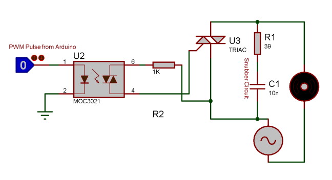
Optocoupler is also known as Optoisolator. It is used to maintain isolation between two electrical circuits like DC and AC signals. Basically, it consists of an LED that emits infrared light and the photosensor which detects it. Here a MOC3021 optocoupler is used to control the AC Fan from the microcontroller signals which is a DC signal.
TRIAC and Optocoupler connection diagram:
3. Potentiometer to control the Fan Speed
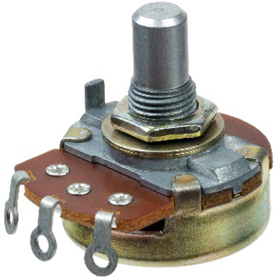
Here a potentiometer is used to vary the speed of AC Fan. We know that a potentiometer is a 3 terminal device that acts as a voltage divider and provides a variable voltage output. This variable analog output voltage is given at the Arduino analog input terminal to set the speed value of the AC fan.

4. PWM Signal Generation Unit
In the final step, a PWM pulse is given to the TRIAC as per the speed requirements, which in turn varies the ON/OFF timing of the AC signal and provides a variable output to control the Fan speed. Here Arduino is used to generate the PWM pulse, which takes the input from the potentiometer and gives PWM signal output to TRIAC and optocoupler circuit which further drives the AC fan at the desired speed. Learn more about PWM generation using Arduino here.
Circuit Diagram
Circuit diagram for this Arduino based 230v fan speed control circuit is given below:

Note: I have shown the complete circuit on a breadboard only for the purpose of understanding. You should not use 220V AC supply directly on your breadboard, I have used a dotted board to make the connections as you can see in the image below

Programming the Arduino for AC fan speed control
After the hardware connection, we need to write up the code for Arduino, which will generate a PWM signal to control the AC signal ON/OFF timing using a potentiometer input. We previously used PWM techniques in many projects.
The complete code of this Arduino AC fan speed control project is given at the bottom of this project. The stepwise explanation of the code is given below.
In the first step, declare all the required variables, which are going to be used throughout the code. Here the BT136 TRIAC is connected to pin 6 of Arduino. And the variable speed_val is declared to store the value of speed step.
int TRIAC = 6;
int speed_val =0;
Next, inside setup function, declare the TRIAC pin as output as PWM output will be generated through this pin. Then, configure an interrupt to detect the zero-crossing. Here we have used a function called attachInterrupt, which will configure digital Pin 3 of Arduino as external interrupt and will call the function named zero_crossing when it detects any interrupts at its pin.
void setup()
{
  pinMode(LAMP, OUTPUT);
  attachInterrupt(digitalPinToInterrupt(3), zero_crossing, CHANGE);
}
Inside the infinite loop, read the analog value from potentiometer which is connected at A0 and map it to a value range of (10-49).
To find out this range we have to do a small calculation. Earlier it is told that each half cycle is equivalent to 10,000 microseconds. So here the dimming will be controlled in 50 steps which is an arbitrary value and can be changed. Here the minimum steps are taken as 10, not Zero because 0-9 steps give approximately the same power output and maximum steps are taken as 49 as it is not recommended practically to take the upper limit (which is 50 in this case).
Then each step time can be calculated as 10000/50= 200 microseconds. This will be used in the next part of the code.
void loop()
{
    int pot=analogRead(A0);
    int data1 = map(pot, 0, 1023,10,49);
    speed_val=data1;
}
In the final step, configure the interrupt-driven function zero_crossing. Here the dimming time can be calculated by multiplying the individual step time with no. of steps. Then after this delay time, the TRIAC can be triggered using a small high pulse of 10 microseconds which is sufficient to turn on a TRIAC.
void zero_crossing()
{
  int chop_time = (200*speed_val);
  delayMicroseconds(chop_time);
  digitalWrite(TRIAC, HIGH);
  delayMicroseconds(10);
  digitalWrite(TRIAC, LOW);
}
Complete code along with a working video for this AC fan control using Arduino and PWM is given below.
Complete Project Code
int TRIAC = 6;

int speed_val=0;

void setup()

{

  pinMode(TRIAC, OUTPUT);

  attachInterrupt(digitalPinToInterrupt(3), zero_crossing, CHANGE);

}

void zero_crossing()

{

  int chop_time = (200*speed_val);

  delayMicroseconds(chop_time);

  digitalWrite(TRIAC, HIGH);

  delayMicroseconds(10);

  digitalWrite(TRIAC, LOW);

}

void loop()

{

    int pot=analogRead(A0);

    int data1 = map(pot, 0, 1023,10,40);

    speed_val=data1;

}
Comments
Hi @Graham,
Thanks for your insightful comment. I understand your reaction, as you look like you really know what you're talking about! However, I think the article addresses an interesting topic which as too few available resources over the internet. You suggest removing the post from Circuit Digest, and I get why you'd want that to prevent beginners from making mistakes, particularly when handling mains current. But how about writing a better article that follows the safety rules? Wouldn't that make this article de-facto obsolete and therefore redirect beginners away from its unsafe design? I for one would love to read a good article on this topic!
Have a nice day.
Thanks for the detailed insights Graham. This helps newbies to be aware before trying out such things.
Hello!
After the transformer and before the 4N25 why don't you use a rectifier?
I want to do the same but instead of a potentiometer I want to use a temperature sensor in order to control the speed of fan.
Hi Vasileios, Here 4N25 is only used to detect the zero crossing points that can be detected from both AC and DC pulses. Hence there is no Mandatory needs to use 4N25 here. And if you want to add temperature sensor instead of Potentiometer, you can do it very easily making a little changes in the program.i.e you have to map the sensor output values to analog step values. Hope this answers your question!!! Thank you
it works !! Thanks!!
where i am living does not sell opto 4N25 ... only sell 4N35, i have used that alternative .. but the circuit is not yet running
How do you create PWM? If I am not mistaken, to create PWM, you should use analogWrite().
Hello,
I'm a last year college student who's performing the same project, for my college project assessment, which you showed in your article and connected the circuit just as you showed but couldn't get the same results as you showed in the video.
Please, I'd like to verify your wire connection of this model and code. And please explain how your model works.
As I'm new in this particular area

This is a DANGEROUS and bad design.
Do not attempt to build this circuit, unless you have mains circuit experience.
Encouraging amateurs to play with mains devices like this is inviting trouble.
The TRIAC and Transformer circuits should be fused, None shown!
Exposed mains in TRIAC connector block. Dont touch!
No MAINS EARTH connected to on transformer or motor!
The crude circuit diagram does not follow safe rules, nor is the correct TRIAC shown.. The negative (black) wire is shown passing under the mains wiring.
Never use a prototyping board for mains work, they are not mains voltage rated.
Bad circuit design
1. There is no resistor or reverse voltage protection diode on the 4N25 used as a so called zero crossing controller. Using the 4N25 as shown, it’s surprising the internal LED has not failed. Opto coupler LEDS like all LEDs require current limiting. Used in an AC circuit a reverse connected diode must be connected to the opto-coupler input LED prevent the reverse voltage, in this case >12V peak on 9V transformer, exceeding the internal LED reverse voltage of 5V. It is surprising the Opto LED has not gone up in smoke and that the circuit is working at all.
2. The 4N25 opto coupler will NOT provide zero crossing. It will turn on until the AC +V wave voltage exceeds 1.6V and will turn off when the voltage drops below 1.6V. Therefore is not a zero crossing detector!
3. Series resistor between the MC3021 and TRIAC are usually 100 ohm, not 1K as shown.
4. No transient snubber circuit across the TRIAC. Transient snubber should be used especially with an inductive load such as a motor.
Can I ask to have this posting and circuit removed from Circuit Digest?