
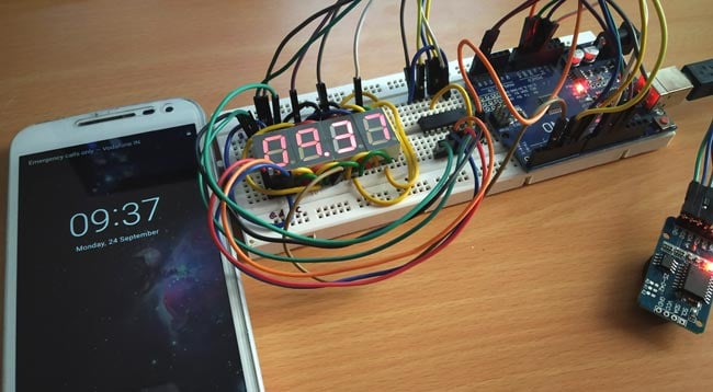
Digital wall Clocks are getting more popular now days and they are better than analog clock as it provides accurate time in hours, minutes and seconds and its easy to read the values. Some digital clocks also have many facilities like displaying temperature, humidity, setting multiple alarms etc. Most of the digital clocks use seven segment display.
We previously built many digital clocks circuits either using 7 segment displays or using 16x2 LCD. Here you can the complete PCB designs of AVR based Digital clock. This tutorial is about making a Digital clock by multiplexing four- 7 segment displays using Arduino UNO and displaying the time in HH:MM format.
Components Required
- 4-Digit 7 Segment Display
- 74HC595 IC
- DS3231 RTC Module
- Arduino UNO
- Breadboard
- Connecting wires
4-Digit 7 Segment Display
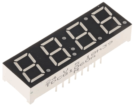
4-digit 7 Segment display has four seven segment display joined together or we can say multiplexed together. They are used to display numerical values and also some alphabets with decimals and colon. The display can be used in both direction. Four digits are useful for making digital clocks or like counting numbers from 0 to 9999. Below is the internal diagram for 4-Digit 7 Segment display.
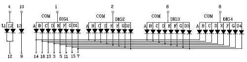
Each segment has one LED with individual LED control. There are two types of seven segment displays such as Common Anode and Common Cathode. The above image shows the common anode type 7 segment display.
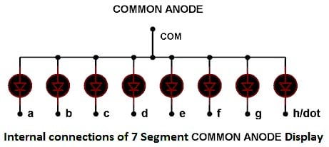
Common Anode
In Common Anode, all the positive terminals (Anodes) of all the 8 LEDs are connected together, named as COM. And all the negative terminals are left alone or connected to the microcontroller pins. By using microcontroller, if logic LOW is set to illuminate the particular LED segment and set logic High to turn OFF LED.
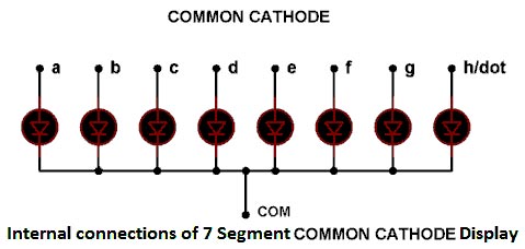
Common Cathode
In Common Cathode, all the Negative terminals (cathode) of all the 8 LEDs are connected together, named as COM. And all the positive terminals are left alone or connected to the microcontroller pins. By using microcontroller, if set logic HIGH to illuminate the LED and set LOW to turn OFF LED.
Learn more about 7 segment displays here and check how it can be interfaced with other microcontrollers:
- 7 Segment Display Interfacing with Arduino
- 7 Segment Display Interfacing with Raspberry Pi
- Interfacing Seven Segment Display with ARM7-LPC2148
- 7 Segment Display Interfacing with PIC Microcontroller
- 7 Segment Display Interfacing with 8051 Microcontroller
74HC595 Shift Register IC
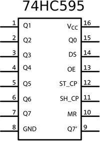
The IC 74HC595 also known as 8-Bit Serial IN – Parallel OUT Shift Register. This IC can receive data input in serial and can control 8 output pins in parallel. This is useful in reducing pins used from microcontroller. You can find all the 74HC595 shift register related projects here.
Working of 74HC595 IC:
This IC uses three pins such as Clock, Data & Latch with the microcontroller to control the 8 output pins of the IC. The clock is used to provide continuously pulses from microcontroller and data pin is used to send the data like which output needs to be turned ON or OFF at the respective clock time.
Pinout:
|
Pin Number |
Pin Name |
Description |
|
1,2,3,4,5,6,7 |
Output Pins (Q1 to Q7) |
The 74HC595 has 8 output pins out of which 7 are these pins. They can be controlled serially |
|
8 |
Ground |
Connected to the Ground of microcontroller |
|
9 |
(Q7) Serial Output |
This pin is used to connect more than one 74HC595 as cascading |
|
10 |
(MR) Master Reset |
Resets all outputs as low. Must be held high for normal operation |
|
11 |
(SH_CP) Clock |
This is the clock pin to which the clock signal has to be provided from MCU/MPU |
|
12 |
(ST_CP) Latch |
The Latch pin is used to update the data to the output pins. It is active high |
|
13 |
(OE) Output Enable |
The Output Enable is used to turn off the outputs. Must be held low for normal operation |
|
14 |
(DS) Serial Data |
This is the pin to which data is sent, based on which the 8 outputs are controlled |
|
15 |
(Q0) Output |
The first output pin. |
|
16 |
Vcc |
This pin powers the IC, typically +5V is used. |
DS3231 RTC Module
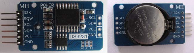
DS3231 is an RTC module. RTC stands for Real Time Clock. This module is used to remember the time and date even when the circuit is not powered. It has a battery backup CR2032 to run the module in absence of external power. This module also includes a temperature sensor. The module can be used in embedded projects such as making digital clock with temperature indicator etc. Here are some useful projects using it:
- Automatic Pet Feeder using Arduino
- Interfacing RTC Module (DS3231) with PIC Microcontroller: Digital Clock
- Interfacing RTC module (DS3231) with MSP430: Digital Clock
- ESP32 Real Time Clock using DS3231 Module
- Digital Wall Clock on PCB using AVR Microcontroller Atmega16 and DS3231 RTC
Pinout of DS3231:
|
Pin Name |
Use |
|
VCC |
Connected to positive of power source |
|
GND |
Connected to ground |
|
SDA |
Serial data pin (I2C) |
|
SCL |
Serial clock pin (I2C) |
|
SQW |
Square Wave output pin |
|
32K |
32K oscillator output |
Features & Specifications:
- RTC counts seconds, minutes, hours and year
- Digital temperature sensor with ±3ºC accuracy
- Register for Aging trim
- 400Khz I2C interface
- Low power consumption
- CR2032 battery backup with two to three-year life
- Operating Voltage: 2.3 to 5.5V

Circuit Diagram

Circuit Connection between DS3231 RTC & Arduino UNO:
|
DS3231 |
Arduino UNO |
|
VCC |
5V |
|
GND |
GND |
|
SDA |
A4 |
|
SCL |
A4 |
Circuit Connections between 74HC595 IC & Arduino Uno:
|
74HC595 IC |
Arduino UNO |
|
11-SH_CP (SRCLK) |
6 |
|
12-ST_CP (RCLK) |
5 |
|
14-DS (Data) |
4 |
|
13-OE(Latch) |
GND |
|
8-GND |
GND |
|
10-MR(SRCLR) |
+5V |
|
16-VCC |
+5V |
Circuit Connections between IC 74HC595 & 4-Digit Seven Segment & Arduino UNO:
|
4-DigitSevenSegment |
IC 74HC595 |
Arduino UNO |
|
A |
Q0 |
- |
|
B |
Q1 |
- |
|
C |
Q2 |
- |
|
D |
Q3 |
- |
|
E |
Q4 |
- |
|
F |
Q5 |
- |
|
G |
Q6 |
- |
|
D1 |
- |
10 |
|
D2 |
- |
11 |
|
D3 |
- |
12 |
|
D4 |
- |
9 |

Programming Arduino UNO for Multiplexing Seven Segment Display
The complete code and working video are attached at the end of this tutorial. In the programming section, how the time (hour and minute) is taken from the RTC module in 24hr format and then it is converted into respective format for displaying them in the 4-digit 7 Segment display will be explained.
To interface the DS3231 RTC module with Arduino UNO the I2C bus of Arduino UNO is used. A library called <DS3231.h> is included in the program to access functions like setting and reading time, date, temperature data etc. Download the DS3231 RTC module Arduino Library. As RTC module uses I2C interface the <wire.h> library is also used in the program.
In this concept, hour and minute are taken first from RTC and they are combined together like 0930 (09:30 pm) and then the individual digits are separated like thousand, hundred, tens, unit and the individual digits converted into binary format like 0 into 63 (0111111). This binary code is sent to a shift register and then from the shift register to the seven-segment, successfully displaying the Digit 0 in seven segment display. This way, the four digits are multiplexed and hour and minute is displayed.
Initially, the necessary library is included such as DS3231 library and Wire library(I2C library).
#include <Wire.h>
#include<DS3231.h>
The pins are defined for the seven segment control. These controls will play important role in multiplexing the display.
#define latchPin 5
#define clockPin 6
#define dataPin 4
#define dot 2
The variables are declared to store the converted or raw result taken from the RTC.
int h;               //Variable declared for hour
int m;              //Variable declared for minute
int thousands;
int hundreds;
int tens;
int unit;


bool h24;
bool PM;
Next the object for the class DS3231 is declared as RTC to simplify the use in further lines.
DS3231 RTC;
As RTC module is interfaced with Arduino by using I2C communication. So, wire.begin() is used to start I2C communication in default address of RTC as there are no other I2C modules.
Wire.begin();
The pin mode are defined, whether the GPIO will behave as output or input.
   pinMode(9,OUTPUT);
    pinMode(10,OUTPUT);
    pinMode(11,OUTPUT);
    pinMode(12,OUTPUT);
    pinMode(latchPin, OUTPUT);
    pinMode(clockPin, OUTPUT);
    pinMode(dataPin, OUTPUT);
    pinMode(dot,OUTPUT);
The loop runs infinitely and it takes the time in hour and minute from the RTC DS3231 module. ‘h24’ indicates the 24hr format variable.
    int h= RTC.getHour(h24, PM);
    int m = RTC.getMinute();
Then the hour and minute is combined as one number (example if hour is 10 and min is 60 then number is 10*100=1000+60 =1060).
int number = h*100+m;
The individual digits from number are obtained (example 1060- 1 is thousand,0 is hundered,1 is tenth and 0 is last digit). To separate the digits, modulus operator is used. For example, in 1060 to get 1 then 1060/1000=1.06%10=1). So separate digits are stored in separate variables.
    int thousands = number/1000%10;
    int hundreds = number/100%10;
    int tens = number/10%10;
    int unit = number%10;
After that a switch case statement for each individual digit is defined for converting them into respective format (binary format) and sending out via shift register to display in 7-segment. For example (For 1 digit it is changed into 06 (0000 0110)). So that it is sent out via shift and 1 digit is displayed in 7-segment (0 for LOW, 1 for HIGH).
switch (t)
{
  case 0:
  unit = 63;
  break;
  case 1:
  unit = 06;
  break;
  case 2:
  unit =91;
  break;
  case 3:
  unit=79;
  break;
  case 4:
  unit=102;
  break;
  case 5:
  unit = 109;
  break;
  case 6:
  unit =125;
  case 7:
  unit = 07;
  break;
  case 8:
  unit = 127;
  break;
  case 9:
  unit =103;
  break;
  }
Then the individual digit in binary format is sent out via ‘shiftout’ function with MSB first and the respective digit pin is made HIGH and latch pin is made HIGH.
    digitalWrite(9, LOW);
    digitalWrite(latchPin, LOW);
    shiftOut(dataPin, clockPin, MSBFIRST,thousands);
    digitalWrite(latchPin, HIGH);
    digitalWrite(9, HIGH);
    delay(5);
This finishes the complete code. Most of the function explanation are given in the code comment section just beside the code line. The frequency of the clock will decide the view of Time and quality of multiplexing I.e. if low clock is used then the flickering can be seen where as if the clock speed is high then there won’t be such flickering and a steady time can be seen.
Note that to access the RTC module, the I2C bus voltage has to be maintained. In order to give any suggestion or if you have any doubt then please comment below.
Complete Project Code
//Four-Digit 7 Segments Multiplexing using Arduino: Display time in HH:MM
//CIRCUIT DIGEST
#include <Wire.h>    //Library for SPI communication
#include <DS3231.h>   //Library for RTC module
#define latchPin 5
#define clockPin 6
#define dataPin 4
#define dot 2
DS3231 RTC;         //Declare object RTC for class DS3231
int h;              //Variable declared for hour
int m;              //Variable declared for minute
int thousands;
int hundreds;
int tens;
int unit;
bool h24;
bool PM;
void setup ()
{
    Wire.begin();
    pinMode(9,OUTPUT);
    pinMode(10,OUTPUT);
    pinMode(11,OUTPUT);
    pinMode(12,OUTPUT);
    pinMode(latchPin, OUTPUT);
    pinMode(clockPin, OUTPUT);
    pinMode(dataPin, OUTPUT);
    pinMode(dot,OUTPUT);
}
void loop ()
{
    digitalWrite(dot,HIGH);
    int h= RTC.getHour(h24, PM);  //To get the Hour
    int m = RTC.getMinute();      //TO get the minute
    int number = h*100+m;         //Converts hour and minute in 4-digit
    int thousands = number/1000%10; //Getting thousands digit from the 4 digit
    int hundreds = number/100%10;  //Getting hundreds digit from 4 digit
    int tens = number/10%10;        //Getting tens digit from 4-digit
    int unit = number%10;           //Getting last digit from 4-digit
    int t= unit;
    int u= tens;
    int v= hundreds;
    int w= thousands;
//Converting the individual digits into corresponding number for passing it through the shift register so LEDs are turned ON or OFF in seven segment
switch (t)
{
  case 0:
  unit = 63;
  break;
  case 1:
  unit = 06;
  break;
  case 2:
  unit =91;
  break;
  case 3:
  unit=79;
  break;
  case 4:
  unit=102;
  break;
  case 5:
  unit = 109;
  break;
  case 6:
  unit =125;
  case 7:
  unit = 07;
  break;
  case 8:
  unit = 127;
  break;
  case 9:
  unit =103;
  break;
  }
switch (u)
{
  case 0:
  tens = 63;
  break;
  case 1:
  tens = 06;
  break;
  case 2:
  tens =91;
  break;
  case 3:
  tens=79;
  break;
  case 4:
  tens=102;
  break;
  case 5:
  tens= 109;
  break;
  case 6:
  tens =125;
  case 7:
  tens = 07;
  break;
  case 8:
  tens = 127;
  break;
  case 9:
  tens =103;
  break;
  }
  switch (v)
  {
  case 0:
  hundreds = 63;
  break;
  case 1:
  hundreds = 06;
  break;
  case 2:
  hundreds =91;
  break;
  case 3:
  hundreds=79;
  break;
  case 4:
  hundreds=102;
  break;
  case 5:
  hundreds = 109;
  break;
  case 6:
  hundreds =125;
  case 7:
  hundreds = 07;
  break;
  case 8:
  hundreds = 127;
  break;
  case 9:
  hundreds =103;
  break;
  }
  switch (w)
  {
  case 0:
  thousands = 63;
  break;
  case 1:
  thousands = 06;
  break;
  case 2:
  thousands =91;
  break;
  case 3:
  thousands=79;
  break;
  case 4:
  thousands=102;
  break;
  case 5:
  thousands = 109;
  break;
  case 6:
  thousands =125;
  case 7:
  thousands = 07;
  break;
  case 8:
  thousands= 127;
  break;
  case 9:
  thousands =103;
  break;
  }
    digitalWrite(9, LOW);
    digitalWrite(latchPin, LOW);
    shiftOut(dataPin, clockPin, MSBFIRST,thousands);  // The thousand digit is sent
    digitalWrite(latchPin, HIGH);  // Set latch pin HIGH to store the inputs
    digitalWrite(9, HIGH);         // Turinig on that thousands digit
    delay(5);                      // delay for multiplexing
    digitalWrite(10, LOW);
    digitalWrite(latchPin, LOW);
    shiftOut(dataPin, clockPin, MSBFIRST,hundreds );    // The hundered digit is sent
    digitalWrite(latchPin, HIGH);
    digitalWrite(10, HIGH);
    delay(5);
    digitalWrite(11, LOW);
    digitalWrite(latchPin, LOW);
    shiftOut(dataPin, clockPin, MSBFIRST,tens);   // The tens digit is sent
    digitalWrite(latchPin, HIGH);
    digitalWrite(11, HIGH);
    delay(5);
    digitalWrite(12, LOW);
    digitalWrite(latchPin, LOW);
    shiftOut(dataPin, clockPin, MSBFIRST,unit);   // The last digit is sent
    digitalWrite(latchPin, HIGH);
    digitalWrite(12, HIGH);
    delay(5);
}
Comments
Back again, digit1 represents thousands , dig2 hundreds, dig3 tens and dig1 units ? I`ve tried to represent just a simple number 1234 on each digit, but all I get is the ignition of all segments on the display.
I also have the same problem did you solve this ? If yes then guide me why all the segment are lights up
error no matching function for call to 'DS3231::DS3231()'
plz help me
