
Display is a very important part of any Embedded System Application as it helps users to know the status of the system and also shows the output or any warning message generated by the system. There are many types of displays used in electronics like 7-segment display, LCD display, TFT touchscreen display, LED display etc.
We already Interfaced 16x2 LCD with ARM7-LPC2148 in our previous tutorial. Today in this tutorial we will interface a 7-segment Display with ARM7-LPC2148. Before going into detail, we will see how to control the 7-segment module to display any number of character.
7-Segment Display
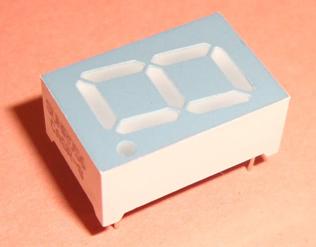
7 segment displays are among the simplest display units to display the numbers and characters. It is generally used to display numbers and has brighter illumination and simpler construction than dot matrix display. And because of brighter illumination, the output can be viewed from larger distance than LCD. As shown in the above image of a 7-segment display, it consists of 8 LEDs, each LED used to illuminate one segment of unit and the 8thLED used to illuminate DOT in 7 segment display. 8thLED is used when two or more 7-segment modules are used, for example to display (0.1). A single module is used to display single digit or character. To display more than one digit or character, multiple 7-segments are used.
Pins of 7-Segment Display
There are 10 pins, in which 8 pins are used to refer a,b,c,d,e,f,g and h/dp, the two middle pins are common anode/cathode of all he LEDs. These common anode/cathode are internally shorted so we need to connect only one COM pin
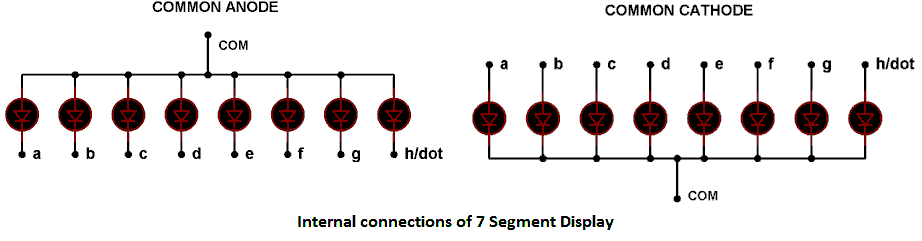
Depending upon connection we classify 7-Segment in two types:
Common Cathode
In this all the Negative terminals (cathode) of all the 8 LEDs are connected together (see diagram below), named as COM. And all the positive terminals are left alone or connected to the microcontroller pins. If we use microcontroller we set logic HIGH to illuminate the particular and set LOW to turn OFF LED.
Common Anode
In this all the positive terminals (Anodes) of all the 8 LEDs are connected together, named as COM. And all the negative thermals are left alone or connected to the microcontroller pins. If we use microcontroller we set logic LOW to illuminate the particular and set logic High to turn OFF LED.
So depending upon the pin value, a particular segment or line of 7 segment can be turned on or Off to display desired number or alphabet. For example to display 0 digit we must set pins ABCDEF as HIGH and only G as LOW. As ABCDEF LEDs are ON and G is OFF this forms the 0 digit in 7-segment module. (This is for common cathode, for common anode it is opposite).
Below table shows the HEX values and corresponding digit according to LPC2148 pins for common cathode configuration.
Digit | HEX Values for LPC2148 | A | B | C | D | E | F | G |
0 | 0xF3 | 1 | 1 | 1 | 1 | 1 | 1 | 0 |
1 | 0x12 | 0 | 1 | 1 | 0 | 0 | 0 | 0 |
2 | 0x163 | 1 | 1 | 0 | 1 | 1 | 0 | 1 |
3 | 0x133 | 1 | 1 | 1 | 1 | 0 | 0 | 1 |
4 | 0x192 | 0 | 1 | 1 | 0 | 0 | 1 | 1 |
5 | 0x1B1 | 1 | 0 | 1 | 1 | 0 | 1 | 1 |
6 | 0x1F1 | 1 | 0 | 1 | 1 | 1 | 1 | 1 |
7 | 0x13 | 1 | 1 | 1 | 0 | 0 | 1 | 0 |
8 | 0x1F3 | 1 | 1 | 1 | 1 | 1 | 1 | 1 |
9 | 0x1B3 | 1 | 1 | 1 | 1 | 0 | 1 | 1 |
IMPORTANT: In the table above I have given the HEX values according to the pins I have used in LPC2148, check the circuit diagram below. You can use whatever pins you want but change hex values according to that.
To learn more about 7-segment display, go through the link. Also check 7-segment display interfacings with other microcontrollers:
- 7 Segment Display Interfacing with Raspberry Pi
- 7 Segment Display Interfacing with PIC Microcontroller
- 7 Segment Display Interfacing with Arduino
- 7 Segment Display Interfacing with 8051 Microcontroller
- 0-99 Counter using AVR Microcontroller
Materials Required
Hardware
- ARM7-LPC2148
- Seven Segment Display Module (Single Digit)
- Breadboard
- Connecting Wires
Software
- Keil uVision5
- Flash Magic
Circuit Diagram
For interfacing 7-segment with LPC2148, no external component is needed as shown in the circuit diagram below:

The table below shows the circuit connections between 7-Segment module & LPC2148
Seven Segment Module Pins | LPC2148 Pins |
A | P0.0 |
B | P0.1 |
C | P0.4 |
D | P0.5 |
E | P0.6 |
F | P0.7 |
G | P0.8 |
Common | GND |

Programming ARM7 LPC2148
We have learnt how to program ARM7-LPC2148 using Keil in our previous tutorial. We use same Keil uVision 5 here to write the code and create hex file, and then upload the hex file to LPC2148 using flash magic tool. We are using USB cable to power and upload code to LPC2148
Complete code with Video explanation is given at the end of this tutorial. Here we are explaining few important parts of the code.
First we need to include the header file for LPC214x series microcontroller
#include<lpc214x.h>
Next set the pins as output
IO0DIR=IO0DIR|0xffffffff
This sets the pins P0.0 to P0.31 as output but we will be using pins (P0.0, P0.1, P0.4, P0.5, P0.6, P0.7, and P0.8) only.
Then set the certain pins at LOGIC HIGH or LOW according to the numerical digit to be displayed. Here we will display values from (0 to 9). We will be using an array that consists HEX values for values 0 to 9.
unsigned int a[]={0xf3,0x12,0x163,0x133,0x192,0x1b1,0x1f1,0x13,0x1f3,0x1b3};
Values will be displayed continuously as the code has been put in while loop
while(1)
    {
        for(i=0;i<=9;i++)
        {
            IO0SET=IO0SET|a[i];           //sets corresponding pins HIGH
            delay(9000);                  //Calls delay function
            IO0CLR=IO0CLR|a[i];           //Sets corresponding pins LOW
        }
    }
Here IOSET and IOCLR are used to set pins HIGH and LOW respectively. As we have used PORT0 pins so we have IO0SET & IO0CLR.
For loop is used to increment the i in each iteration and each time when i increments, 7 segment also increments the digit which is showing on it.
delay function is used to generate delay time between SET & CLR
void delay(int k)              //Function for making delay
{
    int i,j;
    for(i=0;i<k;i++)
    for(j=0;j<=1000;j++);
}
Complete code and working video description is given below. Also check all the 7-Segment Display related projects here.
Complete Project Code
//INTERFACING SINGLE SEVEN SEGMENT MODULE WITH LPC2148
//CIRCUIT DIGEST
//By Pramoth.T
#include<lpc214x.h>            //Header file for LPC214x Series microcontrollers
void delay(int );              //Function declaration for delay
int i;                         //Variable declared as integer
unsigned int a[]={0xf3,0x12,0x163,0x133,0x192,0x1b1,0x1f1,0x13,0x1f3,0x1b3}; //integer array with numbers for display
int main()
{
    IO0DIR=IO0DIR|0xffffffff;              //Sets direction as output for PORT 0 pins
    while(1)
    {
        for(i=0;i<=9;i++)
        {
            IO0SET=IO0SET|a[i];           //sets corresponding pins HIGH
            delay(9000);                  //Calls delay function
            IO0CLR=IO0CLR|a[i];           //Sets corresponding pins LOW
        }
    }
    return 0;
}
void delay(int k)              //Function for making delay
{
    int i,j;
    for(i=0;i<k;i++)
    for(j=0;j<=1000;j++);
}
