

In this tutorial we are going to design a 0-99 counter by interfacing two seven segment displays to ATMEGA32A Microcontroller. Here we count events based on number of times button is pressed.
Before moving ahead, let's understand what is a seven segment display. A seven segment display got its name from the very fact that it has seven illuminating segments. Each of these segments has an LED (Light Emitting Diode). You can see the pin diagram of a seven segment display in below image.
The LEDs are fabricated in a manner that lighting of each LED is contained to its own segment. The important thing to notice here, the LEDs in any seven segment display are arranged in common anode mode (common positive) or common cathode mode (common negative).
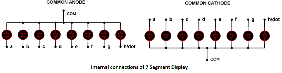
The circuit connection of LEDs in common cathode and common anode is shown in above figure. Here one can observe that, in Common Cathode, the negative terminals of every LED is connected together and brought out as GND. In Common Anode, the positive of every LED is connected together and brought out as VCC. These Common Cathode and Common Anode displays come in very handy while multiplexing several cells together.
Now let’s understand multiplexing. It’s simple a technique used to connect more units in parallel to lessen the pins required, by taking advantage of visual effect. Consider an LED is turning ON and OFF continuously at a rate of 2HZ per second, i.e. it ON two times and OFF two times a second. Now at this rate a human eye can see both ON cycle and OFF cycle. But if frequency is increased to 50HZ, that is 50 ON times and 50 OFF times for the LED in a second. At this rate a human eye cannot see turning OFF cycles at all. This is an effect of vision. At this rate the eye pictures the LED with less brightness and that is all.
Components Required
Hardware: ATMEGA32, Power supply (5v), AVR-ISP PROGRAMMER, HDSP5503, Seven segment displays (two pieces) (any common cathode will do ), 47uF capacitor (connected across power supply), button(three pieces), 10KΩ resistor (two pieces), 1KΩ resistor, 220Ω resistor (two pieces), 100nF capacitor (three pieces), 2N2222 transistors (two pieces).
Software: Atmel studio 6.1, progisp or flash magic.
Circuit Diagram and Working Explanation

The connections which are done for 7 segment display are as follows:
PIN1 or e to PIN (A, 4)
PIN2 or d to PIN (A, 3)
PIN4 or c to PIN (A, 2)
PIN5 or h or DP to PIN (A, 7) /// Not needed as we are not using decimal point
PIN6 or b to PIN (A, 1)
PIN7 or a to PIN (A, 0)
PIN9 or f to PIN (A, 5)
PIN10 or g to PIN (A, 6)
PIN3 or PIN8 or CC to transistor collector
The important thing here is although both segments share same data port to ATMEGA, the Common Cathodes of both displays are connected to two different transistor collectors. Now as of multiplexing, as explained in introduction we are going to turn ON and OFF displays instead of LED.
Here we have two transistors each driving current from each display. What we are doing is, we are going to trigger one transistor for 10ms and another display for an another 10ms, so the display one will be ON for 10ms and then it turns OFF, during this time other display will be ON. Then again display one and so on. This ON and OFF periods are small for the eye to pick so we see both displays ON continuously, which is not the case in real.
There are two buttons present here, one button is for incrementing the display count and another is for decreasing the display count. The capacitors present here is for nullifying the bouncing effect of buttons. If they are removed the controller might count more than one each time the button is pressed.
The resistors connected for pins are for limiting the current, when the button is pressed to pull down the pin to the ground. Whenever a button is pressed, the corresponding pin of controller gets pulled down to ground and thus the controller recognizes that certain button is pressed and corresponding action to be taken - it may be incrementing or decrementing the count depending on button pressed.
The count is displayed in two segments by multiplexing as explained before. The working of this 0-99 counter is explained in step by step of C code given below. You can also read this tutorial if you are working with 8051 microcontroller: 7 Segment Display Interfacing with 8051.
Complete Project Code
#include <avr/io.h> //header to enable data flow control over pins
#define F_CPU 1000000   //telling controller crystal frequency attached
#include <util/delay.h> //header to enable delay function in program
int main(void)
{
DDRB = 0x00; // Taking portB as input port
DDRA = 0xFF; //taking porta as output port
DDRD = 0b11111111; //taking portd as output
int DISPLAY1 [10] = {0x3F,0x06,0x5B,0x4F,0x66,0x6D,0x7D,0x07,0x7F,0x67};
//character display values from 0-9
int c = 0;
int i=0;
int d = 0;
int one = 0; //memory for storing ones place value
int ten =0; //memory for storing tens place value
while(1)
{
if (bit_is_clear(PINB,0)) //when button one  is pressed
{
if (i<21)
{
i++; //increment integer ‘i’ by one if its less than 21
}
}
if (bit_is_clear(PINB,1)) // when button 2  is pressed
{
if (d<21)
{
d++; // increment integer ‘d’ by one if its less than 21
}
}
if (i>20) //if ‘i’ was executed more than 21 times
{
if (c<99) //if counter value less than 99
{
c++; //increment counter value
}
i=0; //put i to zero
}
if (d>20) // if ‘d’ was executed more than 21 times
{
if (c>0) //if counter value is greater than 0
{
 c--; //decrease the value by one
}
d=0; //put d to zero
}
if (c<10) // if counter value is less than 10
{
one = c; // ones place is equal to counter value or c
ten = 0; // tens place is equal to zero as ‘c’ value is less than 10
}
 if (c>=10) //if count value is greater than or equal to 10
{
ten = c/10;//as intergers cannot hold decimal points(12/10=1.2),for integer its‘1’
one = c-(ten*10);//ones place
}
PORTD |=(1<<PIND6); //turn ones place displaying display transistor ON
PORTA = DISPLAY1[one]; //put value at porta which is needed for corresponding digit display
_delay_ms(10); //wait for vision illusion
PORTD &=~(1<<PIND6); // turn ones place displaying display transistor OFF
PORTD |=(1<<PIND5); // turn tens place displaying display transistor ON
PORTA = DISPLAY1[ten]; //put value at porta which is needed for corresponding digit display
_delay_ms(10);
PORTD &=~(1<<PIND5);// turn tens place displaying display transistor OFF
}
}
Comments
Thanks
I have some problems running through this project...can u help me??
Can I switch display to show "0" after pushing two buttons at once - so it would be reset ;)
Did you use a 9V battery for power supply ? If not, then how did you provide power supply to the circuit?
Why don't you use resistors for diods about 220 Ohm. They Vf = 2V and you have Vcc=5 V. I is about 20mA in standard so we need about 150 Ohm resistor, so can be 220 Ohm. I thought it is nessesary, don't you think ?
Regards !
Hi,
why we don't connect on every input for 7segment display 220 Ohm resistor?
Because we have connected Resistor at the common point (cathode) of the 7 segment, which can work for all because all LEDs are connected in parallel.
Do you offer for sale this counter circuit? This circuit is perfect to drive the 2.3 inch high LED displays we will package in a shuffleboard game scoring unit. Ideally, there would be a driver capable of driving two red display digits facing one direction and two reflecting the identical score but displayed in the reverse direction. The same would be repeated for two blue digits. If necessary we can use all red displays.

Great stuff...