 with MSP430: Digital Clock")
In this tutorial we will make a Digital Clock by interfacing RTC module DS3231 with MSP430 and display the time and date on 16x2 LCD. The MSP-EXP430G2 is a Development Tool a.k.a LaunchPad provided by the Texas Instruments to learn and practice on how to use their Microcontrollers. This board falls under the MSP430 Value Line category where we can program all the MSP430 series Microcontrollers. If you are new to MSP then check our getting started with MSP430 tutorial.
Materials Required:
- MSP430
- DS3231 RTC module
- POT -10k
- LCD Module 16*2
- Connecting wires
- Breadboard
What is RTC??
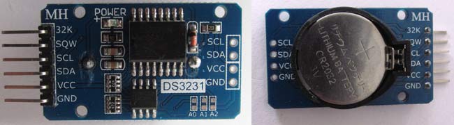
DS3231 is a RTC (Real Time Clock) module. It is used to maintain the date and time for most of the Electronics projects. This module has its own coin cell power supply using which it maintains the date and time even when the main power is removed or the MCU has gone through a hard reset. So once we set the date and time in this module it will keep track of it always. There are several types of RTC ICs available like DS1307, DS3231 etc.
We have previously used RTC with Other microcontrollers in below projects:
- Automatic Pet Feeder using Arduino
- Arduino Data Logger
- Interfacing RTC Module (DS3231) with PIC Microcontroller
- Raspberry Pi Alarm Clock
Note: When using this module for the first time you have to set the date and time. You can also use RTC IC DS1307, we have previously used DS1307 with Arduino.
Connecting the DS3231 RTC with MSP430:
Circuit diagram for MSP430 Microcontroller based Digital Clock is given below. As told earlier the DS3231 works with the help of I2C communication so it will have a Serial Clock (SCL) and a Serial Data (SDA) pin which has to be connected to the I2C pins on our MSP430 which is the pin 9(PIN 2.1,SCL) and pin 10 (PIN 2.2,SDA).
MSP430 gives 3.3V Vcc but we need 5V to connect it with LCD and RTC module. So, we will use a hack, there is a jumper available named as TP1 near USB cable connector. You can take 5V from there.
Circuit Diagram:
 with MSP430: Digital Clock")
Programming MSP430 for RTC Module:
Here we are using Energia IDE for programming. It is same as Arduino IDE and easy to use. If you are new to MSP and energia, then go through getting started with MSP using Energia IDE. To interface RTC module we need library for this board. Download RTC library from this link and install it.
We also need Wire (used for I2C communication) and liquidcrystal libraries which are preinstalled in Energia IDE.
Complete code for this MSP430 digital clock is given at the end of this article. Code is simple and easily understandable. Here we are explaining few parts of it.
First, we have to include necessary libraries.
Below library is for I2C communication between RTC module and MSP430. SDA and SCK pins are already defined in this library, so we don’t have to declare these pins separately.
#include <Wire.h>
Then we have included RTClib.h library for RTC clock and LiquidCrystal.h for LCD functions.
#include "RTClib.h"
#include <LiquidCrystal.h>
After this, we have to create an instance to initialize our RTC module.
RTC_DS3231 rtc;
Then make an array of size 7 and store all seven days with name in it.
char daysOfTheWeek[7][12] = {"Sunday", "Monday", "Tuesday", "Wednesday", "Thursday", "Friday", "Saturday"};
Here is Pins declaration of MSP430 to be used by LCD display: (RS(P2.0),EN(P1.4),D4(P1.5),D5(P2.3),D6(P2.4),D7(P2.5))
LiquidCrystal lcd(8 ,6, 7,11,12,13);
In void setup(), we have initialized the interface to the LCD screen and RTC and specified the dimensions (width and height) of the display, begin() needs to be called before any other library commands.
void setup () {
 lcd.begin(16, 2);
   lcd.setCursor(3,0);
  lcd.print("RTC Clock");
  delay(3000);
  lcd.clear();
  rtc.begin();
  //  rtc.adjust(DateTime(F(__DATE__), F(__TIME__)));
}
NOTE: In above function, commented line is important. When Time and Date is not set, uncomment the line and upload the program. This function store time of your computer at the time of Compilation, so make sure your computer’s time is correct.
Now, Time shown on display is correct but there is a problem, every time you restart/reset your microcontroller, LCD will show Time at which you uploaded the code. This is because rtc.adjust() function has stored the time of your computer, so when you reset, it starts with that time.
To fix this problem, first upload the program with rtc.adjust() function uncommented. Then, immediately comment the same line and upload the program again. Now, your date and time is set and will not be affected by resetting the microcontroller.
In loop function we takes date and time from RTC module and store in the predefined variable called now and display it on LCD using lcd.print() function.
void loop () {
    DateTime now = rtc.now();
    lcd.clear();
     lcd.setCursor(3,0);
   lcd.print(now.day(), DEC);
    lcd.print("/");….
…….
Complete code and Video is given below.
Complete Project Code
#include <Wire.h>

#include "RTClib.h"

#include <LiquidCrystal.h>

RTC_DS3231 rtc;

char daysOfTheWeek[7][12] = {"Sunday", "Monday", "Tuesday", "Wednesday", "Thursday", "Friday", "Saturday"};

LiquidCrystal lcd(8 ,6, 7,11,12,13);

void setup () {

lcd.begin(16, 2);

  lcd.setCursor(3,0);

  lcd.print("RTC Clock");

  delay(3000);

  lcd.clear();

  rtc.begin();

  //  rtc.adjust(DateTime(F(__DATE__), F(__TIME__)));

}
void loop () {

    DateTime now = rtc.now();

    lcd.clear();

    lcd.setCursor(3,0);

    Serial.print(now.year(), DEC);

    Serial.print('/');

    lcd.print(now.day(), DEC);

    lcd.print("/");

    lcd.print(now.month(), DEC);

    lcd.print("/");

    lcd.print(now.year(), DEC);

    lcd.setCursor(1,5);

    lcd.print(daysOfTheWeek[now.dayOfTheWeek()]);

    lcd.print(",");

    lcd.print(now.hour(), DEC);

    lcd.print(":");

    lcd.print(now.minute(), DEC);

    lcd.print(":");

    lcd.print(now.second(), DEC);

    delay(1000);

}

Hello!
I did this project and everything works fine, but time and date is shown just for 3 seconds.
Can You help me please ?