

We're building an Arduino automatic pet feeder today that feeds your pet automatically at scheduled times. This complete automatic pet feeder project incorporates a DS3231 RTC (Real Time Clock) Module, allowing you to keep track of your pet's eating schedule and properly schedule feeding at specific times. Our tested design is one of the best pet feeders for DIY makers that is reliable and inexpensive.
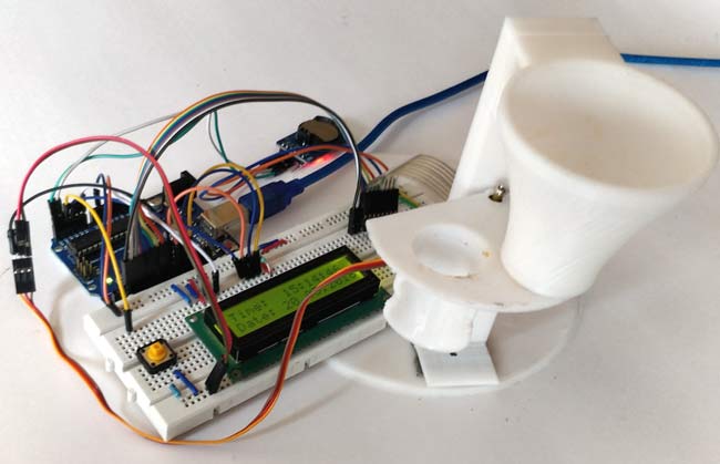
In this circuit, we are using a 16*2 LCD to display the time using the DS3231 RTC Module with Arduino UNO. Also, a servo motor is used to rotate the containers to provide the food, and a 4*4 matrix keypad is used to manually set up the time for feeding the Pet. You can set the rotation angle and container opening duration according to the quantity of food you want to serve to your pet. The quantity of food may also depend on your pet, whether it’s a dog, cat or bird.
Automatic Pet Feeder using Arduino - Quick Overview
Build Time: 6-8 hours | Cost: $40-60 | Difficulty: Intermediate
What You'll Learn: RTC programming, Servo motor control, Keypad input, LCD interfacing
Applications: Pet feeding automation, Timed dispensing, Small animal care, Customizable portion control
Table of Contents
- Essential Components
- Circuit Diagram and Wiring Guide
- Container Design and Assembly
- DS3231 Real-Time Clock Module Setup
- └ Some Features
- Complete Arduino Code
- └ Installing Required Arduino Libraries
- Step-by-Step Operation
- Testing and Calibration
- GitHub Repository
- Frequently Asked Questions
- Related DIY Arduino Projects
Essential Components for Arduino Automatic Pet Feeder Project
These carefully selected components ensure optimal performance for your automatic pet feeder using Arduino:
- Arduino UNO
- 4*4 Matrix Keypad
- 16*2 LCD
- Push Button
- Servo Motor
- Resistor
- Connecting Wires
- Breadboard
Best Automatic Pet Feeder Circuit Diagram and Wiring Guide
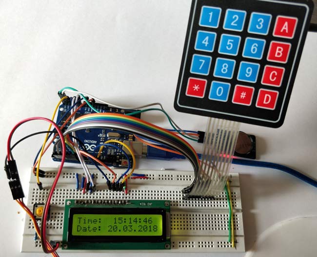
In this Arduino based Cat Feeder, for Getting Time and Date, we have used the RTC (Real Time Clock) Module. This automatic pet feeder circuit diagram shows the complete wiring configuration for the Arduino automatic pet feeder. We have used the 4*4 Matrix Keypad to set the Pet’s eating time manually with the help of a 16x2 LCD. The Servo motor rotates the container and drops the food at the time set by the user. The LCD is used for displaying the Date and Time. Complete working can be found in the Video given at the end.

This configuration allows reliable key detection for programming feeding schedules in your automatic pet feeder project.
3D-Printed Pet Feeder Container Design and Assembly
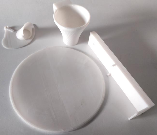
We have designed this Arduino automatic pet feeder container using a 3D printer. You can also print the same design by downloading the files from here. The material used for printing this model is PLA. It has four Parts as shown in the image below:
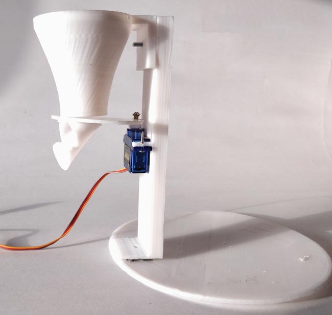
Assemble the four parts and connect the Servo Motor as shown in the picture below:
If you are new to 3D printing, here is the starting guide. You can download the STL files for this pet feeder here. Ensure secure connections and proper alignment for the smooth operation of your best automatic pet feeder design.
DS3231 Real-Time Clock Module Setup for Pet Feeding Timer
DS3231 is an RTC (Real Time Clock) module. It is used to maintain the date and time for most of the Electronics projects. This module has its coin cell power supply, using which it maintains the date and time even when the main power is removed or the MCU has gone through a hard reset. So once we set the date and time in this module, it will keep track of it always. In our circuit, we are using DS3231 to feed the pet according to the time, set up by the Pet’s owner, like an alarm. As, clock reaches the set time, it operates the servo motor to open the container gate, and the food drops into the Pet’s food bowl.
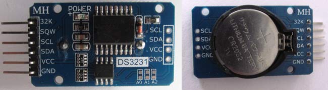
Some Features for Pet Feeding Apps:
» Temperature-compensated crystal oscillator ensures accurate feeding times
» Battery backup enables the device to maintain time when power supply interruptions occur
» I2C communication interface for easy Arduino integration
» Under normal operating conditions, 8-10years battery life.
Note: When using this module for the first time, you have to set the date and time. The module will then maintain accurate timekeeping for your automatic pet feeder project. You can also use the RTC IC DS1307 for reading the time with Arduino.
Complete Arduino Code for Automatic Pet Feeder Programming
Automatic Pet Feeder Complete Arduino Code is given at the end. The complete Arduino automatic pet feeder code is provided below with detailed explanations for easy customisation and troubleshooting.
Arduino has default libraries for using the Servo motor and LCD 16*2 with it. But for using the DS3231 RTC Module and 4*4 Matrix Keypad with the Arduino.
Installing Required Arduino Libraries
Download and install these essential libraries for your automatic pet feeder project:
In the below code, we are defining libraries, “#include <DS3231.h>” for the RTC module, “#include <Servo.h>” for the Servo Motor, “#include <LiquidCrystal.h>” for 16*2 LCD, and “#include <Keypad.h>” for 4*4 Matrix Keypad.
#include <DS3231.h>
#include <Servo.h>
#include <LiquidCrystal.h>
#include <Keypad.h>
In the below code, we are defining the keymap for the 4*4 matrix keypad and assigning the Arduino pins for the rows and Columns of the keypad.
char keys[ROWS][COLS] = {
  {'1','2','3','A'},
  {'4','5','6','B'},
  {'7','8','9','C'},
  {'*','0','#','D'}
};
byte rowPins[ROWS] = { 2, 3, 4, 5 };
byte colPins[COLS] = { 6, 7, 8, 9 };
Here, we are creating the keypad by using the command below in the code.
Keypad kpd = Keypad( makeKeymap(keys), rowPins, colPins, ROWS, COLS );
Assigning A4 and A5 Arduino pins to connect with the SCL and SDA pins of DS3231. Also, assigning pins to the LCD and initialising the Servo motor.
DS3231  rtc(A4, A5);
Servo servo_test;      //initialize a servo object for the connected servo
LiquidCrystal lcd(A0, A1, A2, 11, 12, 13); // Creates an LC object. Parameters: (rs, enable, d4, d5, d6, d7)
In the below code, we are declaring t1 to t6, key, and array r[6], and the feed.
int t1, t2, t3, t4, t5, t6;
boolean feed = true;
 char key;
 int r[6];
In the code below, we are setting up all the components for the start. Like in this code “servo_test.attach(10);” Servo is attached to the 10th pin of the Arduino. Defining A0, A1 and A2 as the Output Pins and initialising the LCD and RTC module.
void setup()
 {
  servo_test.attach(10);   // attach the signal pin of servo to pin9 of arduino
  rtc.begin();
  lcd.begin(16,2);
  servo_test.write(55);
  Serial.begin(9600);
  pinMode(A0, OUTPUT);
  pinMode(A1, OUTPUT);
  pinMode(A2, OUTPUT);
 }
Now, how the loop is working is the important part to understand. Whenever the Pushbutton is pressed, it goes high, meaning 1, which can be read by “buttonPress = digitalRead(A3)”. Now it goes inside the ‘if’ statement and calls the ‘setFeedingTime’ function. Then it compares the real time and the entered time by the user. If the condition is true, which means the real time and the entered time are the same, then the Servo motor rotates to an angle of 100 degrees, and after 0.4seconds of delay, it comes back to its initial position.
void loop() {
lcd.setCursor(0,0);
int buttonPress;
buttonPress = digitalRead(A3);
if (buttonPress==1)
 setFeedingTime();
 lcd.print("Time:  ");
 String t = "";
 t = rtc.getTimeStr();
 t1 = t.charAt(0)-48;
 t2 = t.charAt(1)-48;
 t3 = t.charAt(3)-48;
 t4 = t.charAt(4)-48;
 t5 = t.charAt(6)-48;
 t6 = t.charAt(7)-48;
 lcd.print(rtc.getTimeStr());
 lcd.setCursor(0,1);
 lcd.print("Date: ");
 lcd.print(rtc.getDateStr());
 if (t1==r[0] && t2==r[1] && t3==r[2] && t4==r[3]&& t5<1 && t6<3 && feed==true)
 {
  servo_test.write(100);                   //command to rotate the servo to the specified angle
   delay(400);
  servo_test.write(55);
  feed=false;
 }
 }
In the void setFeedingTime() function code, after pressing the pushbutton, we are able to enter the pet feeding time, then we have to press ‘D’ to save that time. When the saved time matches with real time, then the servo starts rotating.
void setFeedingTime()
{
  feed = true;
   int i=0;
  lcd.clear();
  lcd.setCursor(0,0);
  lcd.print("Set feeding Time");
  lcd.clear();
  lcd.print("HH:MM");
  lcd.setCursor(0,1);
  while(1){
    key = kpd.getKey();
    char j;
  if(key!=NO_KEY){
    lcd.setCursor(j,1);
    lcd.print(key);
    r[i] = key-48;
    i++;
    j++;
    if (j==2)
    {
      lcd.print(":"); j++;
    }
    delay(500);
  }
  if (key == 'D')
  {key=0; break; }
  }
}
How the Arduino Pet Feeder Works - Step-by-Step Operation
After uploading the code to the Arduino Uno, the automatic pet feeder using Arduino displays the current time and date on the LCD. When you pressed the pushbutton, it asked for the Pet’s feeding time, and you had to enter the time using the 4*4 matrix Keypad. The display will show the entered time, and as you press ‘D’, it saves the time. When the real time and the entered time match, it rotates the servo motor from its initial position 55⁰ to 100⁰ and, after a delay, again returns to its initial position. Therefore, the Servo motor is connected to the Food Container gate, so as it moves, the gate will open, and some amount of food will fall into the bowl or plate. After a delay of 0.4 seconds Servo motor rotates again and closes the gate. The whole process completes within a few seconds. This is how your pet gets the food automatically at the time you enter.
Change the time and degree according to the food
Testing and Calibration of Your Arduino Pet Feeder System
Before deploying your best automatic pet feeder, we recommend that you utilise the following methodical testing process:
- Testing to Make Sure the Servos that move the Food Dispensing Mechanism are free of food, to ensure it mechanically operates correctly.
- The LCD shows the correct time, the correct time is shown on the display and the buttons function.
- Keypad input can be read, and the time can be set.
- The amount of food can be calibrated by adjusting the angle of the servos and the time delay.
- Performing multiple test feeds, and
- Lastly will be consistent feeding outputs.
Technical Summary and GitHub Repository
The Technical Summary is a description of the project as simply as possible: key aspects, design, and operational features. The GitHub Repository provides you access to hardware configuration, software logic, and how we interfaced them to get the performance we designed to the source code, schematics, libraries, and documentation to enable replication and/or customisation.


Frequently Asked Questions on Arduino Automatic Pet Feeder
⇥ What size pets can this automatic pet feeder project handle?
The Arduino pet feeder would be best for small to medium pets (cats, small dogs, birds). The servo motor can control the size of the portion, and you can change the length of time that the opening is open, as well as the angle of the container so you can determine how much food you would like to dispense.
⇥ How expensive is this Arduino automatic pet feeder?
The total cost for this project ranges from $40-60. For example, Arduino UNO ($15), DS3231 module ($5), Servo ($8), LCD ($10), keypad ($5) and miscellaneous. In any case, it's much cheaper than a store-bought automatic pet feeder.
⇥ How accurate is the timing of the Arduino automatic pet feeder?
The DS3231 RTC module allows for ±2ppm accuracy with feeding time calculated in seconds; therefore, the feeding will be accurate to within a second. Even when there is a power outage, the backup battery on the module will maintain time, allowing you to feed your pet at the same time every day without interruption.
⇥ Is this the best automatic feeder project for beginners?
This is a project for intermediate Arduino users. The beginner should have a basic understanding of Arduino programming, circuit connections, and what you do with components. This project uses the step-by-step guide to help you gain electronics experience.
⇥ What if the pet feeder servo motor does not rotate?
Check the servo connections to pin 10, check to see how much power is being supplied, make sure the servo has enough current availability, make sure the code is uploaded properly, and check to see that the angle values (55° and 100°) are the operating angles for your servo.
⇥ Can I use alternative components in the automatic pet feeder circuit?
Yes indeed, you can use alternative components. For example, you can substitute DS1307 for the DS3231, choose servos that are different from one another (angular values will need to be adjusted), or use different displays. Please make sure the voltage is acceptable and modify accordingly for the code to work with the different components.
Related DIY Arduino Projects for Smart Home Automation
Take on these complementary Arduino projects that enhance your home automation and pet care setup. From automated plant watering and pet feeding systems to security alarms responding to your dog’s bark and smart water dispensers, these projects bring practical convenience and intelligent control to everyday tasks.

Plant Watering System using Arduino
Learn how to build an automatic plant watering system using Arduino UNO R4 WiFi. Step-by-step guide with circuit diagram, code, and mobile app integration. Perfect for smart gardening!

Dog-Barking-Security-Alarm-using-Arduino
In this project, we are going to build a Dog Barking Security Alarm using Arduino Nano, PIR Motion Sensor, and Dog Barking Sound Module.

Automatic Water Dispenser using Arduino
We build an automatic water dispenser using Arduino and a Solenoid valve that can automatically give you water when a glass is placed near it.
Complete Project Code
#include <DS3231.h>
#include <Servo.h>
#include <LiquidCrystal.h>
#include <Keypad.h>
const byte ROWS = 4; // Four rows
const byte COLS = 4; // Three columns
// Define the Keymap
char keys[ROWS][COLS] = {
  {'1','2','3','A'},
  {'4','5','6','B'},
  {'7','8','9','C'},
  {'*','0','#','D'}
};
// Connect keypad ROW0, ROW1, ROW2 and ROW3 to these Arduino pins.
byte rowPins[ROWS] = { 2, 3, 4, 5 };
// Connect keypad COL0, COL1 and COL2 to these Arduino pins.
byte colPins[COLS] = { 6, 7, 8, 9 };
//  Create the Keypad
  Keypad kpd = Keypad( makeKeymap(keys), rowPins, colPins, ROWS, COLS );

DS3231  rtc(A4, A5);
Servo servo_test;      //initialize a servo object for the connected servo
LiquidCrystal lcd(A0, A1, A2, 11, 12, 13); // Creates an LC object. Parameters: (rs, enable, d4, d5, d6, d7)
 //int angle = 0;
// int potentio = A0;      // initialize the A0analog pin for potentiometer
 int t1, t2, t3, t4, t5, t6;

boolean feed = true; // condition for alarm
 char key;
 int r[6];

 void setup()
 {
  servo_test.attach(10);   // attach the signal pin of servo to pin9 of arduino
  rtc.begin();
  lcd.begin(16,2);
  servo_test.write(55);
  Serial.begin(9600);
  pinMode(A0, OUTPUT);
  pinMode(A1, OUTPUT);
  pinMode(A2, OUTPUT);

 }

 void loop()
 {
lcd.setCursor(0,0);
int buttonPress;
buttonPress = digitalRead(A3);
if (buttonPress==1)
 setFeedingTime();

//Serial.println(buttonPress);
 lcd.print("Time:  ");
 String t = "";
 t = rtc.getTimeStr();
 t1 = t.charAt(0)-48;
 t2 = t.charAt(1)-48;
 t3 = t.charAt(3)-48;
 t4 = t.charAt(4)-48;
 t5 = t.charAt(6)-48;
 t6 = t.charAt(7)-48;

 lcd.print(rtc.getTimeStr());
 lcd.setCursor(0,1);
 lcd.print("Date: ");
 lcd.print(rtc.getDateStr());

 if (t1==r[0] && t2==r[1] && t3==r[2] && t4==r[3]&& t5<1 && t6<3 && feed==true)
 {
  servo_test.write(100);                   //command to rotate the servo to the specified angle
   delay(400);
  servo_test.write(55);
  feed=false;
 }
 }
void setFeedingTime()
{
  feed = true;
   int i=0;
  lcd.clear();
  lcd.setCursor(0,0);
  lcd.print("Set feeding Time");
  lcd.clear();
  lcd.print("HH:MM");
  lcd.setCursor(0,1);

  while(1){
    key = kpd.getKey();
    char j;

  if(key!=NO_KEY){

    lcd.setCursor(j,1);

    lcd.print(key);

    r[i] = key-48;
    i++;
    j++;
    if (j==2)
    {
      lcd.print(":"); j++;
    }
    delay(500);
  }
  if (key == 'D')
  {key=0; break; }
  }
}
Comments
gave all the connections properly and display still shows black box without any letters
Adjust the contrast of the LCD. Also check if connections are made properly
some of the codes i'm trying to upload but i get errors!!Pls help!!
Are there any more pictures of the set up that show the wiring in more detail? We tried to follow it exactly but our LCD is not working. Words are not showing up...
Check if the contrast levels are all fine
It keeps displaying the stuff after the button is pressed without even pressing the button and then sometimes it just doesnt work at all.
What do I have to change in the code if I am using a I2C LCD Display instead of the normal 16 pin one like in this example?
Excuse me what meaning the number 48 has in setting the time.
can anyone upload a picture of the board and the file to their code?
I've tried to wire everything according to the video. However, it is not working.
I'm sorry. We added a potentiometer to adjust the contrast of the LCD, but the words are still very light/cannot be seen. In addition, we cannot change the date. How do we fix this problem? Our project is due soon so any help is appreciated!! Thank you! :)
does anyone have a picture of their board and arduino with their wiring?
does anyone have a modified code?
Mr. Pankaj Khatri,
Do you think you could upload a picture of the setup where we can clearly see where everything is going? The wiring diagram is different from the setup in the video. We aren't sure which to follow.
Follow the circuit digram guys, its the best way to get it done. Dont relay on wiring pictures.
Where it is?
I mean, the fritzing image is a bit unclear to track multiple lines together like in the LCD (especifically) and also but not so hard with the matrix keyboard.
I appreciate your help, but my pets will love your help people! :)
Some of the codes I'm trying to upload but i get errors...Pls help!!
why your data can't verify on arduino uno. have problem on your data please help me i need your help. i want to do this projek for my final year project
What problem are you having? only if you brief that people here might be able to help.
How could I put more "times"? like 2 meals
I need your help because when i write this code it has errors throught
People here can help you only if you brief them with your problems
Can I program several feeding times a day, or only once?
You can easily tweak the Arduino code to feed several times a day
what are the values of required resistors
i can not see the colors clearly. what is the value of the resistors?
thanks
These are just pull-up and pull-down resistors use 4.7K for both and will work fine
DS3231 rtc(A4, A5);
- I am having a trouble with this line in the code
The Error says:
WARNING: Category 'Real-time clock' in library DS3231 is not valid. Setting to 'Uncategorized'
PUSH_BUTTON_KEYPAD_LCD_RTC_SERVO:36: error: no matching function for call to 'DS3231::DS3231(const uint8_t&, const uint8_t&)'
DS3231 rtc(SDA, SCL);
^
C:\Users\Acaer\Documents\Arduino\PUSH_BUTTON_KEYPAD_LCD_RTC_SERVO\PUSH_BUTTON_KEYPAD_LCD_RTC_SERVO.ino:36:21: note: candidates are:
In file included from C:\Users\Acaer\Documents\Arduino\PUSH_BUTTON_KEYPAD_LCD_RTC_SERVO\PUSH_BUTTON_KEYPAD_LCD_RTC_SERVO.ino:1:0:
C:\Users\Acaer\Documents\Arduino\libraries\DS3231/DS3231.h:64:3: note: DS3231::DS3231()
DS3231();
^
C:\Users\Acaer\Documents\Arduino\libraries\DS3231/DS3231.h:64:3: note: candidate expects 0 arguments, 2 provided
C:\Users\Acaer\Documents\Arduino\libraries\DS3231/DS3231.h:60:7: note: constexpr DS3231::DS3231(const DS3231&)
class DS3231 {
^
C:\Users\Acaer\Documents\Arduino\libraries\DS3231/DS3231.h:60:7: note: candidate expects 1 argument, 2 provided
C:\Users\Acaer\Documents\Arduino\libraries\DS3231/DS3231.h:60:7: note: constexpr DS3231::DS3231(DS3231&&)
C:\Users\Acaer\Documents\Arduino\libraries\DS3231/DS3231.h:60:7: note: candidate expects 1 argument, 2 provided
C:\Users\Acaer\Documents\Arduino\PUSH_BUTTON_KEYPAD_LCD_RTC_SERVO\PUSH_BUTTON_KEYPAD_LCD_RTC_SERVO.ino: In function 'void setup()':
PUSH_BUTTON_KEYPAD_LCD_RTC_SERVO:55: error: 'class DS3231' has no member named 'begin'
rtc.begin();
^
C:\Users\Acaer\Documents\Arduino\PUSH_BUTTON_KEYPAD_LCD_RTC_SERVO\PUSH_BUTTON_KEYPAD_LCD_RTC_SERVO.ino: In function 'void loop()':
PUSH_BUTTON_KEYPAD_LCD_RTC_SERVO:80: error: 'class DS3231' has no member named 'getTimeStr'
t = rtc.getTimeStr();
^
PUSH_BUTTON_KEYPAD_LCD_RTC_SERVO:88: error: 'class DS3231' has no member named 'getTimeStr'
lcd.print(rtc.getTimeStr());
^
PUSH_BUTTON_KEYPAD_LCD_RTC_SERVO:91: error: 'class DS3231' has no member named 'getDateStr'
lcd.print(rtc.getDateStr());
^
Multiple libraries were found for "Servo.h"
Used: C:\Users\Acaer\Documents\Arduino\libraries\Servo
Not used: C:\Program Files (x86)\Arduino\libraries\Servo
exit status 1
no matching function for call to 'DS3231::DS3231(const uint8_t&, const uint8_t&)'
.
.
..
pls help me asap, badly need to solve this error
The problem is with your library. You can the wrong or duplicate library, so uninstall all related libraries and use the one given in this article
I try it but it always shows this error:
exit status 1
'DS3231' does not name a type
Can you help me?
What if I want to set 2x what can I do?
...
...
I try this code but after I set the time, it doesnt return to the time and date.
feed = true;
int i=0;
lcd.clear();
lcd.setCursor(0,0);
lcd.print("Set feeding Time");
lcd.clear();
lcd.print("HH:MM");
lcd.setCursor(0,1);
while(1){
key = kpd.getKey();
char j;
if(key!=NO_KEY){
lcd.setCursor(j,1);
lcd.print(key);
r[i] = key-48;
i++;
j++;
if (j==2)
{
lcd.print(":"); j++;
}
delay(500);
}
if (key == 'A')
{key=0; break; }
}
//............................
feed = true;
int u=0
lcd.clear();
lcd.setCursor(0,0);
lcd.print("Set feeding Time");
lcd.clear();
lcd.print("HH:MM");
lcd.setCursor(0,1);
while(1){
key = kpd.getKey();
char j;
if(key!=NO_KEY){
lcd.setCursor(j,1);
lcd.print(key);
r[u] = key-48;
i++;
j++;
if (j==2)
{
lcd.print(":"); j++;
}
delay(500);
}
if (key == 'B')
{key=0; break; }
}
How can i program it using DS1302 RTC and 16x2 lcd with backpack?
lcd showing black boxs how can i solve it
If it is showing black boxes then it means the LCD is working, try adjusting the contrast value using potentiometer. Also check if the data pin connection are done properly
what software application is using to apply the code?
Hi,how to fix black boxes in LCD 16*2?this is only my problem..please show me a guide ..tnx
Black boxes are not a problem, it means that the LCD is initialized by did not receive any data to display.
If you are getting black boxes even after trying to display something on the LCD, then it means you have set the contrast level high, reduce it using the potentiometer
Can someone explain why there is -48 when getting the time
how can i program it i want to set it up at once but multiple sched? like 3 meals
how to fix black box in lcd??
Do you have for 2 meal schedule?
Why it is showing garbage in my lcd
i uesed a potention meter for lcd
how to set 2 times
how to set 3 times
Hi Sir!
After pressing the "setFeedingTime" button, during the 2nd press of # in the keypad, the 1st char seems to be replaced by the 2nd char. Supposedly, it will follow the (j,1) position so it will be printed right after the first char. The colon(:) sign will not be printed on lcd even if the condition "if (j==2)" is met.
And also, when i press the "setFeedingTime" button again, the starting position of char j seems to be moving to the right portion of (j,l) as the start point.
I've followed all the connections above.
Hope somebody could help me on this.
Thank you very much.
did you find the solution
did you find the solution ??
I have also the same problem. Did you solve it already?
Hello Sir,
Can you do liquid filling machine with keypad?
Thanks for sharing...
I'm new in this area and I bought the LCD with I2C and the circuit diagram must change, someone made this with type of configuration like this?.
Thanks a lot.
I have an error with the coding. it keeps a display like below for the #include <keypad.h>
4:10: fatal error: DS3231.h: No such file or directory exit status 1
use #include <DS3231.h> this library , i think you are missing this library or you dont have this library in you arduino IDE software. Download DS3231.h library and include library in sketch section of arduino IDE
how to set the time example i want my date in 20 august 2021 ??
please help me with this error i m really stuck with this error from 2 days
smart_pet_feeder:56:19: error: no matching function for call to 'DS3231::DS3231(const uint8_t&, const uint8_t&)'
DS3231 rtc(A4, A5);
^
In file included from C:\Users\admin\Desktop\SEM 5\IOT\ca2\smart_pet_feeder\smart_pet_feeder.ino:1:0:
C:\Users\admin\Downloads\arduino-1.8.19-windows\arduino-1.8.19\libraries\DS3231/DS3231.h:67:3: note: candidate: DS3231::DS3231(TwoWire&)
DS3231(TwoWire & w);
^~~~~~
C:\Users\admin\Downloads\arduino-1.8.19-windows\arduino-1.8.19\libraries\DS3231/DS3231.h:67:3: note: candidate expects 1 argument, 2 provided
C:\Users\admin\Downloads\arduino-1.8.19-windows\arduino-1.8.19\libraries\DS3231/DS3231.h:66:3: note: candidate: DS3231::DS3231()
DS3231();
^~~~~~
C:\Users\admin\Downloads\arduino-1.8.19-windows\arduino-1.8.19\libraries\DS3231/DS3231.h:66:3: note: candidate expects 0 arguments, 2 provided
C:\Users\admin\Downloads\arduino-1.8.19-windows\arduino-1.8.19\libraries\DS3231/DS3231.h:62:7: note: candidate: constexpr DS3231::DS3231(const DS3231&)
class DS3231 {
^~~~~~
C:\Users\admin\Downloads\arduino-1.8.19-windows\arduino-1.8.19\libraries\DS3231/DS3231.h:62:7: note: candidate expects 1 argument, 2 provided
C:\Users\admin\Downloads\arduino-1.8.19-windows\arduino-1.8.19\libraries\DS3231/DS3231.h:62:7: note: candidate: constexpr DS3231::DS3231(DS3231&&)
C:\Users\admin\Downloads\arduino-1.8.19-windows\arduino-1.8.19\libraries\DS3231/DS3231.h:62:7: note: candidate expects 1 argument, 2 provided
C:\Users\admin\Desktop\SEM 5\IOT\ca2\smart_pet_feeder\smart_pet_feeder.ino: In function 'void setup()':
smart_pet_feeder:87:7: error: 'class DS3231' has no member named 'begin'
rtc.begin();
^~~~~
Using library DS3231 at version 1.1.0 in folder: C:\Users\admin\Downloads\arduino-1.8.19-windows\arduino-1.8.19\libraries\DS3231
Using library Wire at version 1.0 in folder: C:\Users\admin\Downloads\arduino-1.8.19-windows\arduino-1.8.19\hardware\arduino\avr\libraries\Wire
Using library Servo at version 1.1.8 in folder: C:\Users\admin\Downloads\arduino-1.8.19-windows\arduino-1.8.19\libraries\Servo
Using library LiquidCrystal at version 1.0.7 in folder: C:\Users\admin\Downloads\arduino-1.8.19-windows\arduino-1.8.19\libraries\LiquidCrystal
Using library Keypad-3.1.1 at version 3.1.1 in folder: C:\Users\admin\Downloads\arduino-1.8.19-windows\arduino-1.8.19\libraries\Keypad-3.1.1
exit status 1
no matching function for call to 'DS3231::DS3231(const uint8_t&, const uint8_t&)'
i have used correct and dwonloaded with the same link you provided above
can i know once we set the time feeding, we need to set another time or it will repeat the time that we set
Hello sir, please help.. Im doing this project except that I'm using i2c 16x2 lcd, and set feeding time using keypad only, I tried to modified the code, but failed.. Upom analyzing your code, what is the -48 in the code, can someone please explain? Thank you, I badly need help on this...

What an innovation. Salute your creativity :)