Building an automatic plant watering system is becoming increasingly popular among gardening enthusiasts and IoT hobbyists. This DIY automatic plant watering system project helps solve the common problem of forgetting to water plants while away from home. In this complete guide, we'll show you how to make an automatic plant watering system with soil moisture sensing and mobile app control capabilities. We have developed Arduino projects with detailed explanations, circuit diagrams, and code examples for hands-on learning.
Table of Contents
- What is an Automatic Plant Watering System?
- How to make an Automatic Plant Watering System?
- Components Required
- Automatic Plant Watering System Block Diagram
- Automatic Plant Watering System Circuit Diagram
- Hardware Setup Guide
- Blynk Auth Code and Template ID Generation:
- Template Widget Customisation on Blynk Mobile App:
- Automatic Plant Watering System Arduino Code
- Visualising the Plant's Facial Expression through LED Matrix
- Automatic Plant Watering System Working Video
- Projects Similar to the Automatic Plant Watering System
What is an Automatic Plant Watering System?
An Automatic Plant watering system is a device (or setup) that uses sensors to monitor the soil moisture, and if the moisture is low, it will automatically water the plants, typically using a water pump and a microcontroller. This system saves time, reduces water consumption, and ensures plants receive the right amount of water when needed. In this project, we will build such a system, and we will also include some IoT features to water the plants remotely and send SMS alerts when the soil moisture is low.
How to make an Automatic Plant Watering System?
After brainstorming and surfing the internet, I found that building an automatic plant watering system is easy. So first, I created a checklist to determine what things I needed for this project. Most obviously, I need an electric pump to water the plants, and to control the pump, I need a microcontroller. I decided to pick the Arduino UNO R4 for the microcontroller because it has the most powerful RA4M1 microprocessor from Renesas, with the ESP32-S3 from Espressif. With its Wi-Fi capability, we can provide internet access to the microcontroller, which is mandatory to access the microcontroller remotely. This microcontroller also has an inbuilt 12x8 LED matrix, so I was able to display the plant expressions on it. Finally, I need an analog soil moisture sensor so that I can monitor the soil moisture, and based on that, I can switch on/off the water pump remotely through the Blynk app.
Components Required
Below is the detailed list of the components that I am going to use in this project:
Arduino UNO R4 WIFI - 1 NOS
5V single-channel relay module - 1 NOS
5V water pump - 1NOS
FC-28 soil moisture sensor with sensor module - 1 NOS
Connecting jumper wires - REQUIRED NOS
12V DC jack power adapter/5V USB-C power adapter
Mobile phone & Personal computer with an active internet connection
Automatic Plant Watering System Block Diagram
The block diagram gives us a clear view of how this automatic plant watering system will work. Basically, we have the Arduino Uno R4, which will read the soil moisture level using the soil moisture sensor. If the moisture is low, it will automatically turn on the water pump via the relay module.
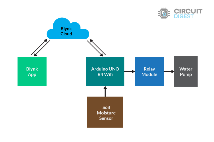
Apart from this, we have also used the Blynk IoT cloud platform to remotely monitor the soil moisture sensor values and turn on the water pump through our mobile application. So the Arduino Uno R4 sends the soil moisture data to the Blynk Cloud, and if a button is pressed on the Blynk mobile app, it is sent to the Arduino Uno via the Blynk Cloud Application.
Automatic Plant Watering System Circuit Diagram
The circuit diagram below uses Arduino UNO R4 WiFi as a main controller, but you can use any other microcontroller by swapping it and making a few modifications to the code. Here, I decided to use Arduino UNO R4 because it has an in-built LED matrix for mimicking plant facial expressions.
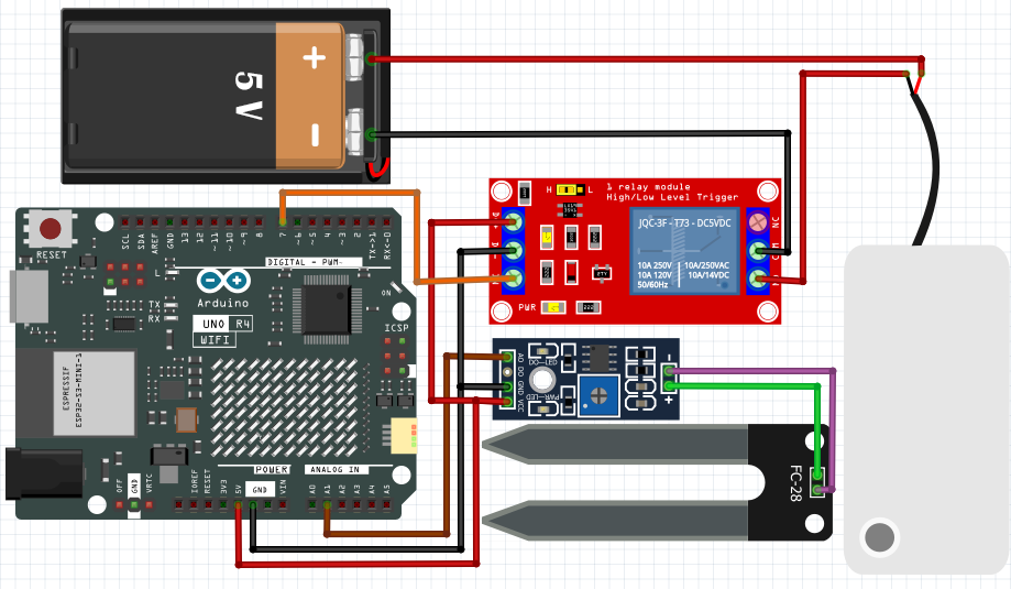
We must ensure the components are connected correctly as per the above circuit diagram. Note that we can't directly drive the water pump from the Arduino UNO R4 Wi-Fi peripheral pins. For that, we need either a motor driver module or a relay module. For simplicity, I opt for a relay module with an external power source.
For the power supply, we can use either an external 12V adapter for powering Arduino through a DC jack, or we can also provide a 5V supply through a USB-C port. For the water pump, we can either power it through an external source or we can use a 5 V power pin from Arduino (only while Arduino is powered by USB-C).
Next, we are going to make our hands dirty. Yes, you are going to build an actual hardware setup by using a circuit diagram as a reference. Before that, carefully read the hardware setup guidelines, especially when choosing a power source for the water pump.
Hardware Setup Guide
In the image below, you can find the actual hardware setup to build an automatic plant watering system using a soil moisture sensor. In this setup, you can find that I am powering the Arduino UNO R4 Wi-Fi through a Type-C USB port. So I don't need to provide an external power supply; I am able to provide a power supply to the water pump from the Arduino 5V pin itself.
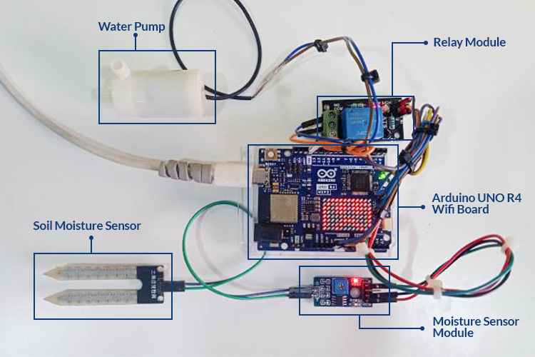
While we power Arduino through a USB port, it bypasses the voltage regulator present on the Arduino Uno R4 Wi-Fi board, so we can consume current up to 2 mA from the 5V pin, which is enough for driving all these things. In the image, you can see that I am using a 5V water pump motor and a single-channel 5V relay module, which has 3 pins on the input side and 3 pins on the output side. On the input side, it has three pins, namely VCC, GND, and the Signal (IN) pin. We can control the relay output using a signal pin by providing either 0V or 5V.

On the other hand, it has three output pins, namely Normally Open (NO), Normally Closed (NC), and Common (COM). But here we use only two relay output pins, the NO and the COM pin, for controlling the water pump motor. We utilise the Normally Open pin to turn the motor off if the Signal pin is low and vice versa.
You can also find the soil moisture sensor with a sensor module, where this module has 4 pins, namely VCC, GND, A0 (analog output pin), and D0 (digital output pin). But in our project, we use an analog pin (A0) to get the analog sensor value. On the other hand, it has two pins, which are usually used for connecting the sensor. It doesn't have a polarity, so no matter how we connect the sensor, it works fine. If you are completely new to soil moisture sensors, you can check out our detailed guide on how to use a soil moisture sensor with Arduino to understand the basics of the sensor and how it works.

The above image shows the working of a soil moisture sensor. Notice how the output voltage of the module decreases from 5V to 0V based ont he water content in the soil. Next, we move on to the microcontroller coding part. But before that, let's discuss how to generate the Blynk auth token and Blynk template ID through a PC, which is crucial for the microcontroller to communicate with Blynk Cloud.
Blynk Auth Code and Template ID Generation:
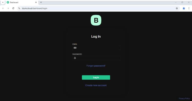
STEP 1: Visit https://blynk.io/. If you don't have a Blynk account, click on signup to create a new account. If you already have an account, then click login and enter your credentials to access the Blynk portal.

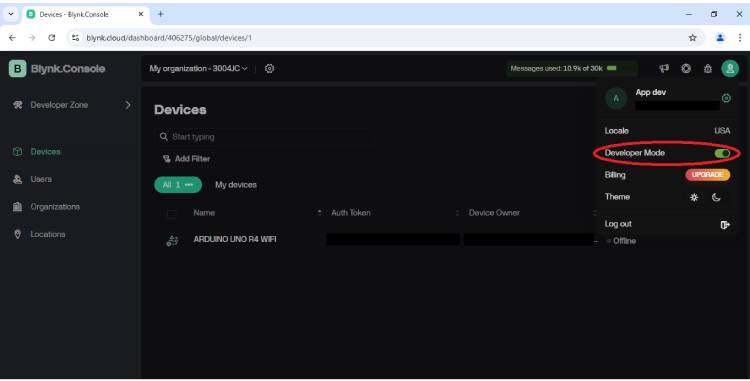
STEP 2: After logging in/signing up, you will see this webpage. To create a template and generate the code, you need to be in developer mode. To check whether you are in developer mode or not, click the profile menu as shown in the image. Then make sure the "developer mode" is enabled and reload the webpage.
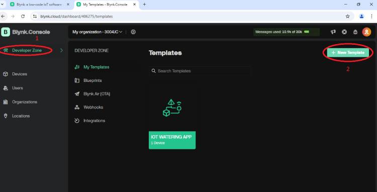
STEP 3: After enabling the developer mode option, select the "Developer zone option" present on the top left corner side, then click on the "new template" present on the top right corner side. It will prompt you to fill in template details. Fill in the details as I mentioned in the image
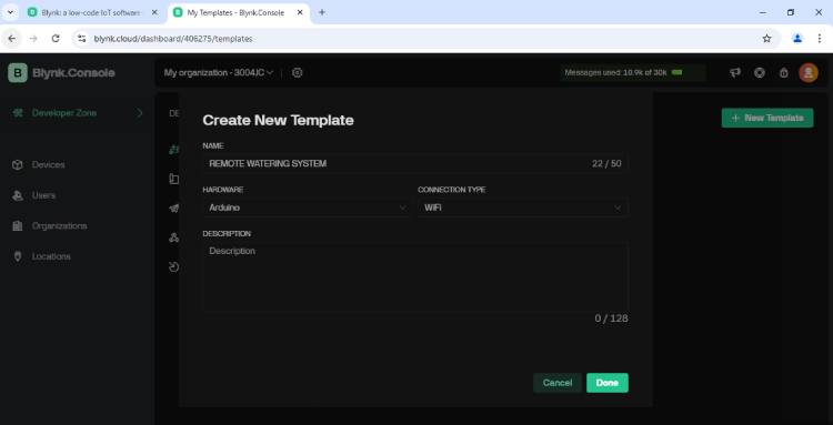
STEP 4: After filling out the template details, click Done. It will move you to the custom template configuration page, where we can customise our template. But our goal is to monitor and control the watering system through the phone; for that, we want to use the "Blynk Mobile app" to customise the template. Anyway, in order to get the template ID and auth code, we need to follow this method on a PC, which is not possible.
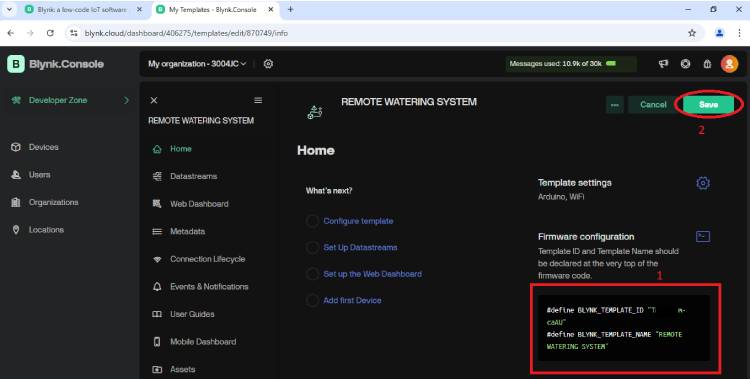
Here you can find the template ID and name; just copy and save it. So that we can include it in our microcontroller code. After copying, just click save to save the template.
STEP 5: Still, we need the Blynk auth code. To obtain the auth code, we need to create a device, which is going to utilise this template. For that, we need to click on the "Devices" option, then click on "New Device" to create a new device.
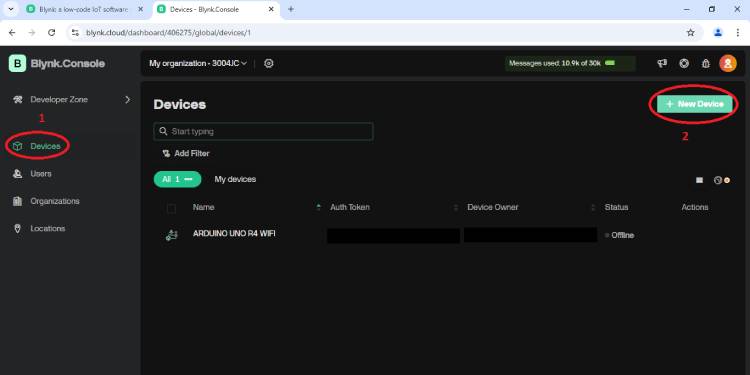
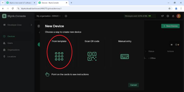
STEP 6: After clicking "New device", it will ask in which way to create a device. Click the option "From template."
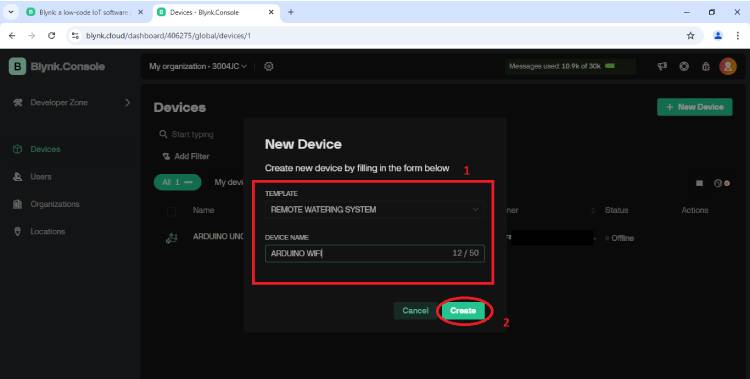
Then it will ask for the device name and which template it is going to use. For the template, use our previously created template, "Remote Watering System." Here, I use "Arduino Wifi" as a device name. After filling out the details, click Create.
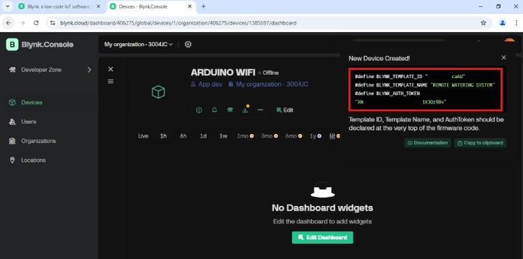
STEP 7: After clicking Create, the new device will be created. In the top right corner, you can find the Blynk auth code and the previously noted template details. Just copy and save it for microcontroller coding usage.
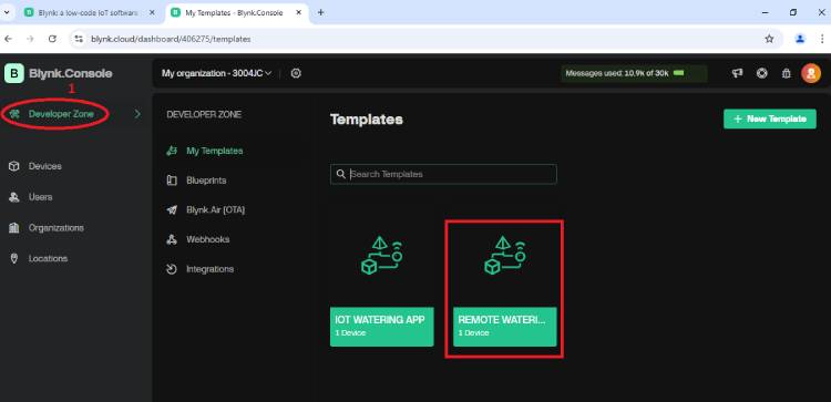
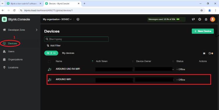
That's all, finally, we generated the Blynk auth code and template details. Here you can see our newly created device and template
Template Widget Customisation on Blynk Mobile App:
Previously, we discussed how to generate the Blynk auth code and template ID through PC. Now, here we are moving on to how to customise the template widget in mobile phones for monitoring the soil moisture level and controlling the water pump.
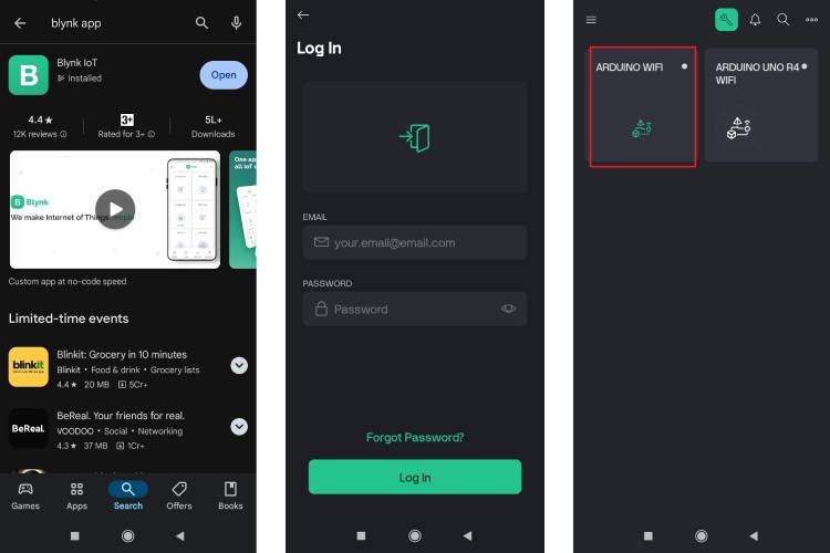
STEP 1: Install the latest "Blynk IoT" mobile app from your respective mobile app store.
STEP 2: After installing, just open the app. It asks you to log in/sign up. We already created a Blynk account for the Auth code and template ID generation. So use that account credential for logging in.
STEP 3: After logging in, you can find our previously created device on the app home page.
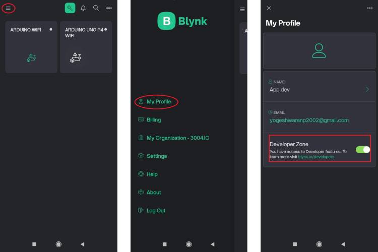
STEP 4: To customise our template, we want to ensure that we are in developer mode. To find out, just click the line symbol in the left corner. It will show you many options; on that, click the "My Profile" option. It will show you the "Developer zone" status. If it is off, just turn it on.
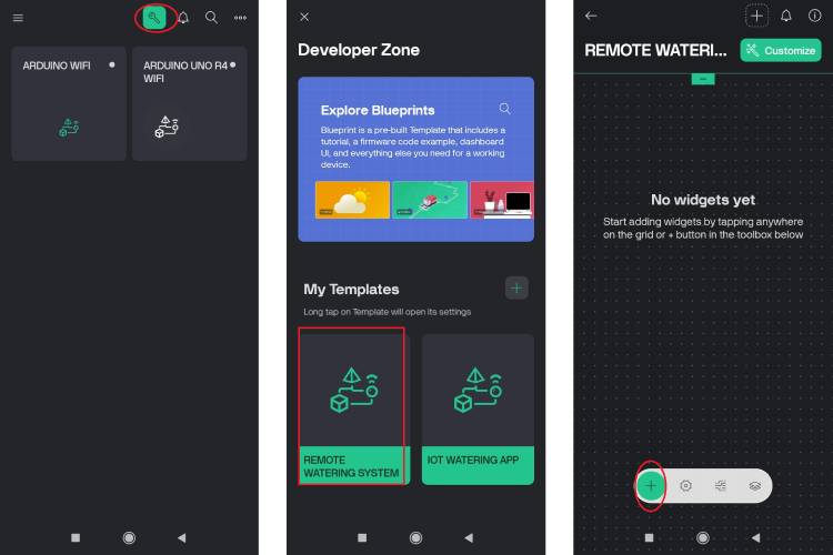
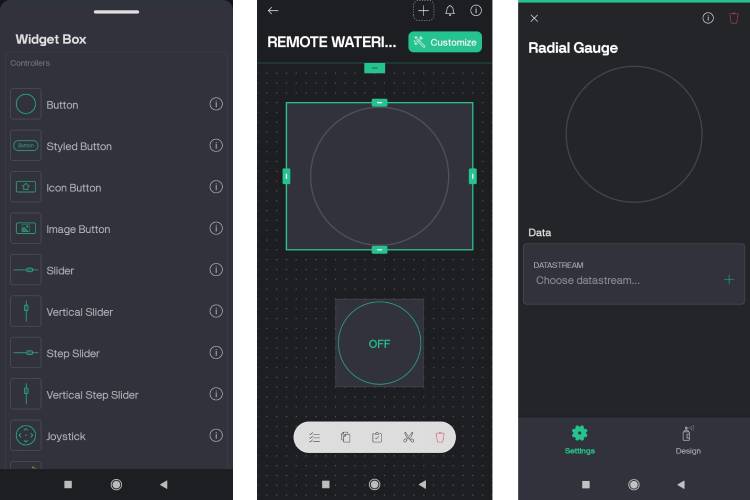
STEP 5: After that, click on the "spanner symbol" on the top side of the home page. You can find our previously created template. Click our template to customise the widgets. Click on the "+" symbol for importing the required widgets.
STEP 6: Generally, we need only two widgets: a button for controlling the water pump and a Radial gauge for monitoring the soil moisture. After importing the two widgets, we need to place those widgets properly and adjust their size for an enhanced user experience. After widget placement, we want to create virtual pins for those widgets.
To create the virtual pin for the radial gauge, we want to single-tap that widget. Later, it asks us to create a data stream as shown in the image.
STEP 7: After clicking “Choose datastream”, create a virtual data stream pin for the Radial gauge. By clicking the create virtual PIN datastream button, enter the virtual PIN. After following the steps as shown in the image, we can create a virtual pin V0 for the Radial gauge.
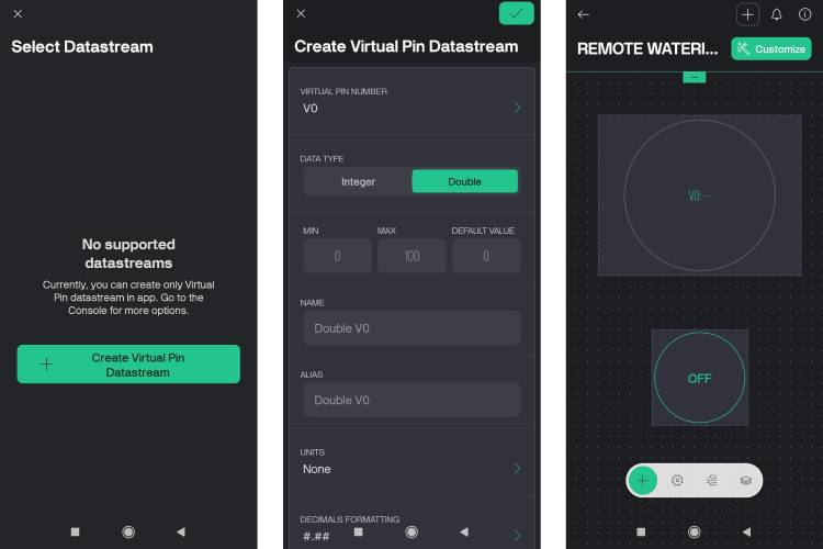
While creating a virtual datastream pin, we chose the data type as double to get precise data and also used the 0 to 100 range to display the percentage value.
STEP 8: We created the virtual pin for the radial gauge. Now we want to create a new virtual pin for the Button widget by clicking "create new" and following the steps shown in the image below, because the V0 pin is specifically for the radial gauge.
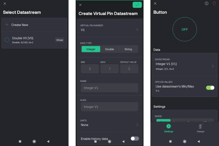
Here, we choose V1 data as an integer, and it has only two states, either 0 or 1. It sends data "1" in the on state and "0" in the off state.
STEP 9: At last, we created the virtual pin datastream pins for both widgets. Later, we can also customise widgets' visuals, like how they should appear in the phone's dark and light modes. We can also give a Title to each of the widgets
To modify the widgets visually, we need to single-tap the widgets present on our template. After tapping, we can find the "Design" symbol present at the bottom. Click that "Design" symbol, and now you can explore widget visual customisation options
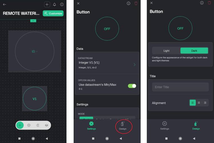
STEP 10: After widget visual customisation, you can see its exact user interface by clicking your device that is found on the app's home page.
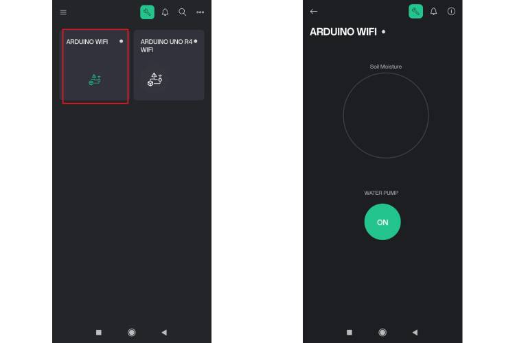
Note: It's not necessary to use the same widgets for your application. However, make sure that the virtual pins mapped in the app template and in the microcontroller code are the same.
Automatic Plant Watering System Arduino Code
First of all, that code allows the microcontroller to access the internet by connecting to the available known Wi-Fi hotspot. After accessing the internet, the controller can access the Blynk cloud by using the Blynk auth token. Here, Blynk Cloud acts as a data streamer between the microcontroller and the Blynk app.
After Blynk authorisation, the code makes the microcontroller keep on fetching soil moisture data from the sensor, and based on that data, it drives the onboard LED matrix to bring out different expressions like sad, normal, and happy.
At the same time, it also forwards moisture data to the Blynk cloud and continuously polls for any incoming pump on/off command from the Blynk cloud. Based on the incoming command, it makes the microcontroller turn on/off the water pump.
Here you can find the source code with an explanation for each section. The following header files are critical for accessing the Blynk cloud server
#define BLYNK_TEMPLATE_ID "XXXXXXXXXXX"
#define BLYNK_TEMPLATE_NAME "XXXXXXXXXXXX"
#define BLYNK_AUTH_TOKEN "XXXXXXXXXXXXX"
These are the necessary header files needed while using predefined functions
#include <SPI.h>
#include <WiFiS3.h>
#include <BlynkSimpleWifi.h>
#include "Arduino_LED_Matrix.h"
#include <EEPROM.h>
Here, we define the soil moisture sensor pin and the relay module signal pin
#define moisture_sensor A0
#define relay 7
These are the necessary objects for Blynk and the LED matrix's predefined functions
BlynkTimer timer;
ArduinoLEDMatrix matrix;
Here user wants to enter our Wi-Fi username and password for providing internet access to the microcontroller
char ssid[] = "XXXXXXXXX";                 //WIFI NAME
char pass[] = "XXXXXXXXXXX";          //WIFI PASSWORD
These are important variables for storing the sensor data, EEPROM address, and reading the water pump status from the Blynk cloud
int eeprom_addr = 0;                                  //eeprom address
int sensorValue = 0;                                  // variable to store the value coming from the sensor
int  pump_status = 0;
int prev_pump_status = 0;
float moist_percent = 0.00;
Used for bringing sad, happy, and normal facial expressions on LED matrix
const uint32_t HAPPY_LED[] = {
   0x3fc48a95,
   0x58019fd9,
   0x5889871
};
const uint32_t NORMAL_LED[] = {
   0x3fc40298,
   0xd98d8019,
   0x5889871
};
const uint32_t SAD_LED[] = {
   0x3fc48a9d,
   0xd8898018,
   0x71889905
};
This function works inside the blink timer_loop, and it is used for continuously reading data from the Blynk cloud and utilising the EEPROM function to make sure the controller retains the water pump status even after a power reset
BLYNK_WRITE(V1){
        pump_status = param.asInt();
        EEPROM.write(eeprom_addr,pump_status);
        prev_pump_status = EEPROM.read(eeprom_addr);
        Serial.println(prev_pump_status);
        Serial.println(pump_status);
}
This function is used to send water moisture sensor data to the Blynk cloud
void sendSensor(){
      Blynk.virtualWrite(V0,moist_percent);
}
This function initialises and sets the microcontroller peripherals, ADC, and LED matrix
void init_renesas_MCU_IO(){
 pinMode(relay, OUTPUT);
 pinMode(moisture_sensor, INPUT);
 analogReadResolution(12);                           //change to 12-bit resolution
 matrix.begin();                                                  //initialise the led matrix*/
}
This function is used for tracking the soil moisture level, based on which it will bring back the facial expression on the LED matrix. For eg, it brings a sad face, if the moisture percentage is low, a Normal face, if the moisture percentage is normal, and a Happy face, if the moisture percentage is High.
void track_soil_moisture(){
  sensorValue = analogRead(moisture_sensor);
  moist_percent = 100 - ((float)sensorValue / 4096.0) * 100;

   if(moist_percent >= 0 && moist_percent < 33.33){
           Serial.println("DRY");
           matrix.loadFrame(SAD_LED);
    }
   else if(moist_percent >= 33.33 && moist_percent < 66.66){
         Serial.println("MODERATE");
        matrix.loadFrame(NORMAL_LED);
    }
   else if(moist_percent >= 66.66 && moist_percent <= 100){
        Serial.println("WET");
       matrix.loadFrame(HAPPY_LED);
   }
}
This setup function is considered the starting point of the program, used for setting up the Blynk server, serial monitor, Blynk timer, and using EEPROM.read() to get the previous water pump status after a power reset.
void setup()
{
   Serial.begin(9600);
   Blynk.begin(BLYNK_AUTH_TOKEN, ssid, pass);
   init_renesas_MCU_IO();
   timer.setInterval(1000L,sendSensor);
   prev_pump_status = EEPROM.read(eeprom_addr);
   pump_status = prev_pump_status;
 }
This loop function keeps on executing after the setup function executes its task
void loop()
{
 Blynk.run();
 timer.run();
 track_soil_moisture();
if(pump_status == 0){
    Serial.println("Water pump is off");
    digitalWrite(relay, LOW);
  }
  else if(pump_status == 1){
    Serial.println("Water pump is on");
    digitalWrite(relay,HIGH);
  }
  delay(500);
}
Visualising the Plant's Facial Expression through Led Matrix:
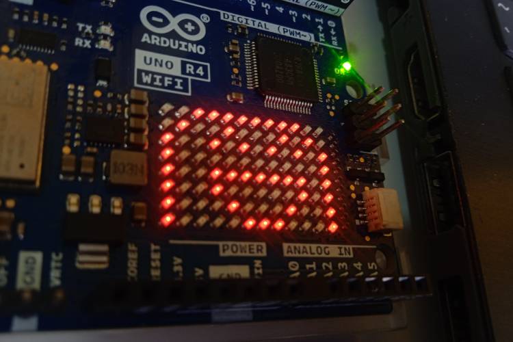
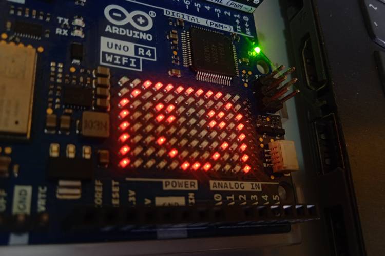
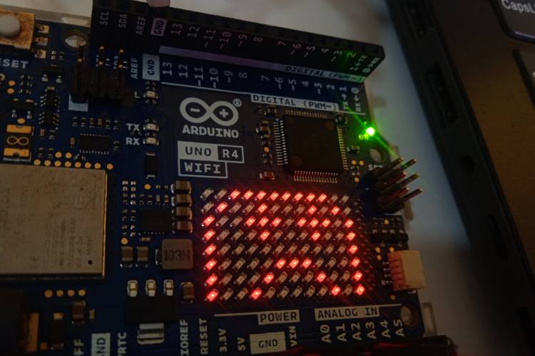
If you follow the above code explanation, you can understand that we can bring the plant's expression on the LED matrix based on the soil moisture sensor reading. In the images, you can find expressions like Happy, Normal, and Sad.
As I previously told you, these expressions appear based on the soil moisture level. Let's take a scenario: if the soil is very wet, it brings out a laughing expression on the LED matrix.
If the soil has a tiny amount of moisture, it brings out a Smile expression on the LED matrix, as you can find in the image.
If the soil is very dry, it brings out a sad expression on the LED matrix, as shown in the image.
That is it, now we have completed our automatic plant watering system mini project. All that is left is to keep it powered on, put the pump inside a water container, and see how it works. Let's do exactly that next!
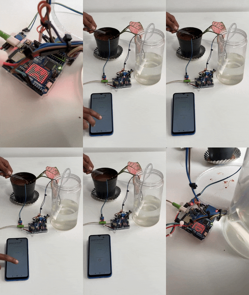
Automatic Plant Watering System Working Video
The video was taken during the working stage of our project, where we were able to water the plants anytime and anywhere.
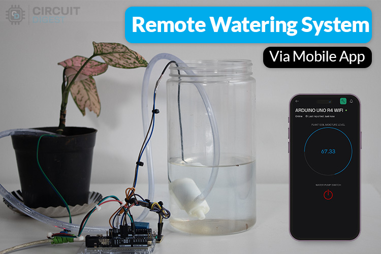
In the image, you can see the customised Blynk app widget on the mobile phone for controlling the water pump motor using the ON-OFF button, and we can also monitor real-time soil moisture levels.
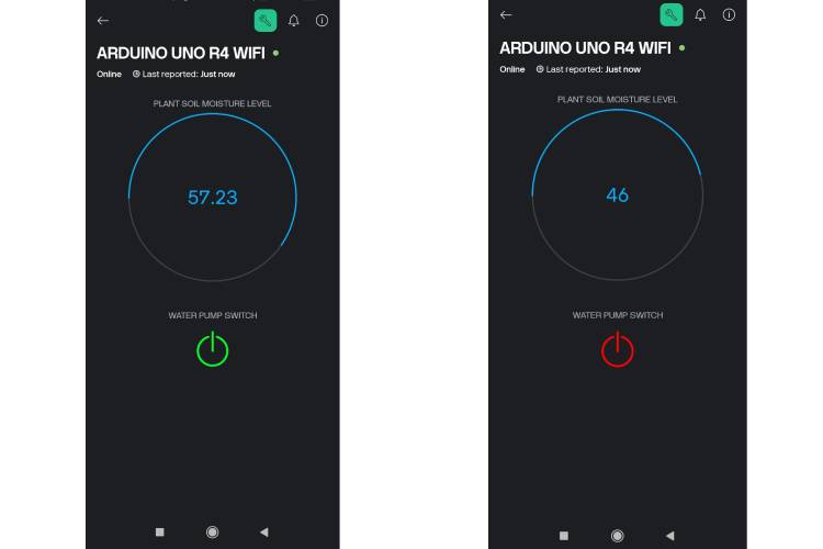
So finally we can make our remote plant watering system, where we can control the water pump and get to know about the plant’s soil from anywhere around the world. What we just needed was a mobile phone with an active internet connection.
Here is the link to our GitHub repo, where you'll find the source code for this project.
Projects Similar to the Automatic Plant Watering System.
Previously, we have built a lot of electronics projects, including a few related to automatic plant watering systems. I have listed all similar projects below; each project is explained in detail with its circuit diagram and code so that you can build it on your own.
Arduino Smart Irrigation System Using ESP32 and Blynk App
In this project, we'll explore an IoT-based irrigation system using the ESP32 board and the Blynk app. It's a project based on the Internet of Things (IoT), and the smart irrigation system offers numerous possibilities to automate the entire irrigation process. Here, we're creating a plot-based smart irrigation system using the ESP32 Controller, a soil moisture sensor, a water level sensor, a relay module and a DHT22 Sensor.
Automatic Irrigation System using an Arduino Uno
In this project, we are making an Automatic Irrigation System with an Arduino Uno, which will irrigate your plants automatically and keep them healthy even when you are out of town for weeks or months. In this project, a Moisture sensor will be used to maintain the optimum level of moisture for your plants.
IoT based Smart Irrigation System using Soil Moisture Sensor and ESP8266 NodeMCU
This Smart irrigation System has a wide scope to automate the complete irrigation system. Here we are building a IoT based Irrigation System using an ESP8266 NodeMCU Module and a DHT11 Sensor. It will not only automatically irrigate the water based on the moisture level in the soil but also send the Data to ThingSpeak Server to keep track of the land condition.
IoT-based Smart Agriculture Monitoring System
In this project, we are going to build a Smart Farming System using IoT. The objective of this project is to offer assistance to farmers in getting Live Data (Temperature, Humidity, Soil Moisture, and soil temperature) for efficient environment monitoring, which will enable them to increase their overall yield and quality of products.
Complete Project Code
/*************************************************************
 Automatic plant watering system Arduino Code
More details : https://circuitdigest.com/microcontroller-projects/build-a-simple-plant…
************************************************************/
/* Comment this out to disable prints and save space */
//#define BLYNK_PRINT Serial
/* Fill in information from Blynk Device Info here */
#define BLYNK_TEMPLATE_ID "xxx"
#define BLYNK_TEMPLATE_NAME "IOT WATERING APP"
#define BLYNK_AUTH_TOKEN "xxxx-lDh"
#include <SPI.h>
#include <WiFiS3.h>
#include <BlynkSimpleWifi.h>
#include "Arduino_LED_Matrix.h"
#include <EEPROM.h>
#define moisture_sensor A0
#define relay 7
BlynkTimer timer;
ArduinoLEDMatrix matrix;  //Create an led matrix object
// Your WiFi credentials.
// Set password to "" for open networks.
char ssid[] = "Semicon Media";
char pass[] = "xxxxx";
int eeprom_addr = 0;  //eeprom address
int sensorValue = 0;  // variable to store the value coming from the sensor
int prev_pump_status = 0;
int pump_status = 0;
float moist_percent = 0.00;

const uint32_t HAPPY_LED[] = {
   0x3fc48a95,
   0x58019fd9,
   0x5889871
};
const uint32_t NORMAL_LED[] = {
   0x3fc40298,
   0xd98d8019,
   0x5889871
};
const uint32_t SAD_LED[] = {
   0x3fc48a9d,
   0xd8898018,
   0x71889905
};

BLYNK_WRITE(V1){     //read data from Blynk cloud
 pump_status = param.asInt();
 EEPROM.write(eeprom_addr,pump_status);
 prev_pump_status = EEPROM.read(eeprom_addr);
 Serial.println(prev_pump_status);
 Serial.println(pump_status);
}
void sendSensor(){   //send data to Blynk cloud
 Blynk.virtualWrite(V0,moist_percent);
}
void init_renesas_MCU_IO(){
 pinMode(relay, OUTPUT);
 pinMode(moisture_sensor, INPUT);
 analogReadResolution(12); //change to 12-bit resolution
 matrix.begin(); //initialise the led matrix*/
}
void track_soil_moisture(){

 // read the value from the sensor:
  sensorValue = analogRead(moisture_sensor);
  moist_percent = 100 - ((float)sensorValue / 4096.0) * 100;

 if(moist_percent >= 0 && moist_percent < 33.33){
   Serial.println("DRY");
   matrix.loadFrame(SAD_LED);
 }
 else if(moist_percent >= 33.33 && moist_percent < 66.66){
   Serial.println("MODERATE");
   matrix.loadFrame(NORMAL_LED);
 }
 else if(moist_percent >= 66.66 && moist_percent <= 100){
   Serial.println("WET");
   matrix.loadFrame(HAPPY_LED);
 }
}
void setup()
{
 // Debug console
 Serial.begin(9600);
 Blynk.begin(BLYNK_AUTH_TOKEN, ssid, pass);
 init_renesas_MCU_IO();

 timer.setInterval(1000L,sendSensor);
 prev_pump_status = EEPROM.read(eeprom_addr);
 pump_status = prev_pump_status;
}
void loop()
{
 Blynk.run();
 timer.run();

 track_soil_moisture();
 if(pump_status == 0){
   Serial.println("Water pump is off");
   digitalWrite(relay, LOW);
 }
 else if(pump_status == 1){
   Serial.println("Water pump is on");
   digitalWrite(relay,HIGH);
 }
 delay(500);
}


