

Whether you're a beginner learning how to connect a soil moisture sensor with Arduino or building advanced automatic plant watering systems, this step-by-step tutorial covers everything you need. We'll show you the exact Arduino soil moisture sensor wiring diagram, provide working Arduino soil moisture sensor code, and guide you through common troubleshooting scenarios that every maker encounters.
In this article, we are going to interface a soil moisture sensor with Arduino and measure the volumetric concentration of water inside the soil. This Arduino moisture sensor module is designed in a way that it can output data in both digital and analog modes. We will read this data and display the output status with an LED for digital output, and we will use the serial monitor to display the analog output. Before we get further, let's make it clear that the soil moisture sensor is also called a soil humidity sensor, so we will be using these two terms interchangeably. Now, without further ado, let's get right into it. In this article, we will interface a soil moisture sensor with Arduino and measure the volumetric amount of water present in the soil. This Arduino moisture sensor module comes in both digital and analog output modes.
Update: This article was updated in June 2025 with more troubleshooting features, and the Arduino soil moisture sensor programming code was also tested to work with the latest Arduino UNO R4 Wifi Development board.
Table of Contents
Soil Moisture Sensor Pinout
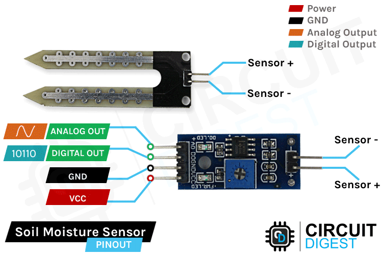
The Soil moisture sensor Arduino, a.k.a the soil humidity sensor, has four pins: VCC, GND, Aout, Dout. These four pins can be used to get the soil moisture data from the sensor, The pinout of the Soil Moisture Sensor is as follows:
Pin Configuration Table
| Pin | Function | Connection | Voltage Level |
| VCC | Power Supply | Arduino 5V | 3.3V - 5V |
| GND | Ground | Arduino GND | 0V |
| AOUT | Analog Output | Arduino A0-A5 | 0-5V variable |
| DOUT | Digital Output | Arduino D2-D13 | 0V/5V (LOW/HIGH) |
VCC is the power supply pin of the soil moisture sensor that can be connected to 3.3V or 5V of the supply. But do note that the analog output will vary depending on the provided supply voltage.
GND is the ground pin of the board, and it should be connected to the ground pin of the Arduino
DOUT is the Digital output pin of the board; output low indicates soil moisture is appropriate, and high indicates soil moisture is low.
AOUT is the Analog output pin of the board that will give us an analog signal between VCC+ and ground for your soil moisture sensor Arduino project.
Arduino Soil Moisture Sensor Specifications
| Specification | Value | Notes |
| Operating Voltage | 3.3V - 5V | 5V recommended for Arduino UNO |
| Output Type | Analog & Digital | Dual output capability |
| Analog Output Range | 0-1023 (10-bit ADC) | Maps to 0-5V |
| Digital Output | LOW/HIGH | Configurable threshold |
| Probe Material | Nickel-plated | Corrosion resistant |
| Response Time | <1 second | Real-time monitoring |
Arduino Soil Moisture Sensor Working Principle
The working of the soil humidity sensor is pretty simple and straightforward, as you can see in the image below. We just need to stick the fork-shaped conductive probe to the soil, as the probe has two exposed conductive plates that will act as a variable resistor whose resistance will vary depending on the water content in the soil. Understanding the Arduino soil moisture sensor working principle is crucial for successful implementation in your projects.
This resistance of the probe is inversely proportional to the soil moisture of the device. The more water in the soil, the better the conductivity, which will result in lower resistance. The less water in the soil, the poorer the conductivity, which means higher resistance. This Arduino moisture sensor produces an output voltage according to the resistance by measuring which we can determine the moisture level.

The above GIF working of the Soil Moisture sensor shows how the analog output of sensor changes based on the water level in the soil. As you can see, the voltage drops from 5V to 0V when water is added to the soil. You can also see that the signal LED on the board turns on when water is added to the soil. We have not shown how the digital pin works in the above GIF to keep things simple. When water is added to the soil, the digital pin moves from low (0V) to high (5V) with the help of a board comparator op-amp. You can control the sensitivity of this digital pin using the potentiometer (blue) on the module. The sensor's analog output voltage varies inversely with soil moisture content, making it perfect for Arduino soil moisture sensor programming applications.
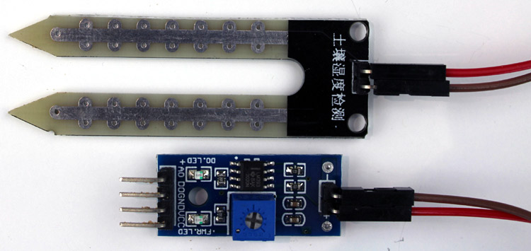
Soil Moisture Sensor - Parts
The entire soil humidity sensor consists of two parts: the first one is the soil moisture sensor probe, and the second one is an electronic module. The module processes the incoming data from the probe and which is processed by a microcontroller like Arduino, and we get the final output. The complete soil moisture sensor Arduino system consists of two main components working together:
The Soil Moisture Sensor Probe:
As we have said earlier, the sensor contains a fork-shaped probe with two big exposed conductive pads. The probe acts like a variable potentiometer, the value of which can be read by a microcontroller like Arduino.
The Soil Moisture Sensor Module:
The soil moisture sensor module is there to convert the incoming analog signal to a digital signal; this is designed in such a way that the sensor can be used without microcontroller support. The module consists of two signal input pins where the probe gets connected. It also has four other pins, two of which are VCC and GND. The other two are Digital Output and Analog Output pins.
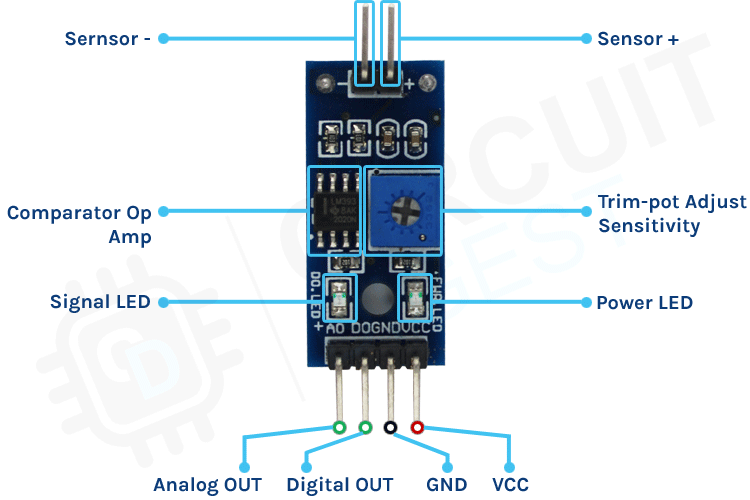
This module also consists of a High Precision Comparator, LM393, that is used to digitise the analog signal coming out of the sensor probe. The module has a built-in potentiometer that is used for sensitivity adjustment of the digital output. The main objective of the potentiometer is to set a threshold, so that when the moisture level exceeds the threshold value, the module will output LOW, otherwise HIGH. This feature of the module can come in very handy because when a certain threshold is reached, you can trigger a relay that can start pumping water.
Sensors should be placed at several different depths and locations in the field. Typically, sensors are placed in pairs at one-third and two-thirds the depth of the crop root zone and at two or more locations in the field, preferably away from high points, depressions and slopes.
When you purchase a soil moisture sensor module, it comes in two parts: the sensing probe and the module with a few components. To fully understand how the sensor module works, we have to look at the circuit of the module. The schematic diagram for the soil moisture sensor module is shown below. The schematic itself is very simple and needs a handful of generic components to build. If you don't have a prebuilt module on hand but still want to test your project, the schematic below will come in handy.

In the schematic, we have an LM393 op-amp, which is a low-power, low offset voltage op-amp that can be powered from a 3.3V or 5V supply. Please note that the analog output voltage of the device will depend on the input voltage. The main job for this op-amp is to convert the incoming analog signal from the sensor probe to a digital signal. There is also this 10K potentiometer that is used to set a reference voltage for the op-amp. The input voltage of the sensor goes below the threshold voltage set by the potentiometer, the output of the op-map goes low. Other than that, we have two LEDs. The first one is a power LED, and the other one is the trigger LED. The power LED turns on when power is applied to the board, and the trigger LED turns on when a certain set threshold is reached. This is how this basic circuit works.
Arduino Soil Moisture Sensor ThinkerCad Simulation
Before testing it on a live circuit, let’s simulate it on Thinker CAD. Here is the Thinkercad simulation for the Arduino Soil moisture sensor.
Click on the start simulation button to test the circuit. You can adjust the sensor value by adjusting the slider that appears when clicking on the sensor. The Tinkercad code for Arduino Soil moisture sensor will show the humidity level using the 5 LEDs connected to Arduino. If you want to edit the code, please click on the code button and modify it as you need.
Arduino Soil Moisture Sensor Circuit – Connection Diagram
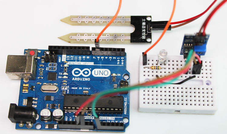
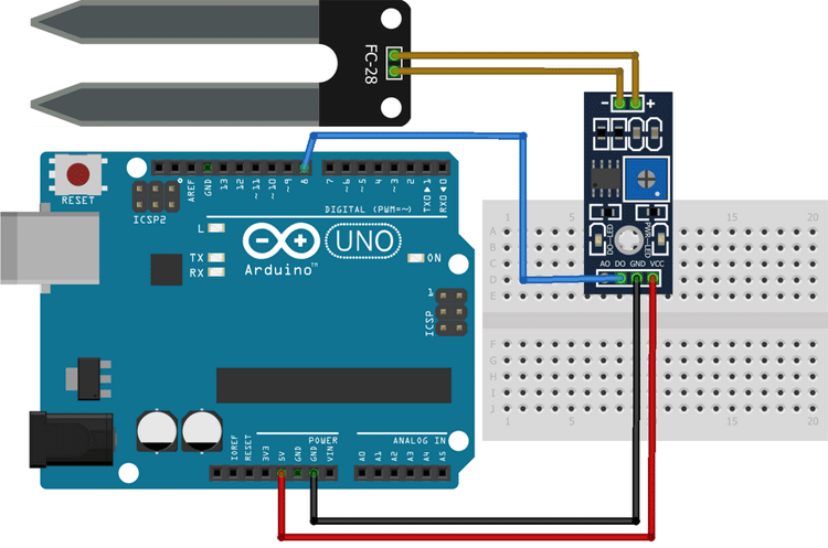
Now that we have a complete understanding of how a Soil Moisture sensor works, we can connect all the required wires to the Arduino UNO board. This section of the article will be divided into two parts, one showing analog output and the one showing the digital output. Let's begin with analog circuitry. The complete circuit to connect a soil humidity sensor with Arduino is shown below. For Arduino soil moisture sensor analog readings, use this proven wiring configuration:
Soil Moisture Sensor - Analog Output:
To work with the sensor, we need to power the sensor first; for that, we are using the 5V and GND pins of the Arduino UNO Board. The soil moisture sensor Arduino circuit diagram shows the internal workings:
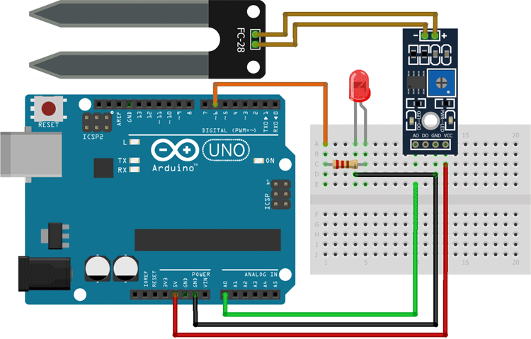
As shown in the above Arduino soil moisture sensor circuit diagram, we have connected an LED to digital PIN 6 of the Arduino and the analog out pin of the sensor is connected to the A0 pin of the Arduino UNO board. Finally, the ground is common between the LED and the sensor. We will program the Arduino so that the brightness of the LED will change depending on the soil moisture data sensed by the probe.
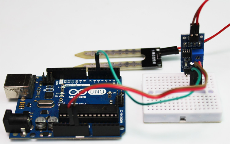
Soil Moisture Sensor - Digital Output:
For the digital interface part, we are also using the +5V and Ground from the Arduino to power the sensor module.
Connecting a soil moisture sensor to an Arduino or any other microcontroller is pretty simple. As we all know, the sensor outputs both analog and digital signals, so processing this signal is very easy.
Common Connection Mistakes to Avoid:
| Mistake | Problem | Solution |
| Using 3.3V instead of 5V | Reduced analog resolution | Always use 5V for optimal performance |
| Loose jumper wires | Intermittent readings | Use quality jumper wires, check connections |
| Missing common ground | Erratic behavior | Ensure all components share Arduino GND |
| Wrong pin assignments | Code errors | Double-check pin connections match code |
- Wrong voltage: Always use 5V, not 3.3V for reliable readings
- Loose connections: Ensure all jumper wires are firmly connected
- Mixed up pins: Double-check AOUT vs DOUT based on your code
- No common ground: All components must share the same ground connection
Quick Connection Verification:
Before uploading code, verify your connections by checking:
- The power LED on the sensor module lights up when the Arduino is powered
- All wire connections are secure and match your circuit diagram
- No short circuits between VCC and GND
- The sensor probe is clean and dry for initial testing
Once your Arduino soil moisture sensor connections are complete, you're ready to upload the code and start monitoring soil moisture levels. The next section covers the complete circuit diagrams with visual references.
Arduino Soil Moisture Sensor Code
The code for the Arduino-based soil moisture sensor is very simple and easy to understand. We are just reading the analog data out of the sensor and changing the brightness of the LED according to the received data. Please do remember that we are only processing the analog data coming out of the sensor; for the digital data, you can see the onboard LED in the module light up.
Here is the link to our GitHub repo, where you'll find the source code, schematics, and other necessary files for this Arduino soil moisture sensor interfacing tutorial. It's a straightforward collection of resources aimed at helping you understand and test the soil moisture sensor interfacing we have discussed in the tutorial.
We initialise our code by declaring two macros, the first one is for the LED, where we will connect an LED, and the second one is the sensorPin through which we are reading the data coming out of the sensor. Here's the complete Arduino soil moisture sensor with LED code for your projects:
// Sensor pins pin D6 LED output, pin A0 analog Input
#define ledPin 6
#define sensorPin A0
Next, we have our setup() function. In the setup function, we initialise the serial with 9600 baud. We also set the ledPin as output, and make the pin LOW. This way, the pin will not float and turn the LED on.
void setup() {
  Serial.begin(9600);
  pinMode(ledPin, OUTPUT);
  digitalWrite(ledPin, LOW);
}
Next, we have our loop() function, in the loop function we print "Analog output:" as text on the serial monitor window and then we call the readSensor() function inside a Serial.println() function so that once the readSensor() function is executed, it returns the data and it also gets printed on the serial monitor window,
void loop() {
  Serial.print("Analog output: ");
  Serial.println(readSensor());
  delay(500);
}
Finally, we have our custom readSensor() function, which returns the analog value that is read through the A0 pin of the Arduino. In the first line of this function, we have declared and defined a variable called sensorValue, where we are putting the raw data that is read through the A0 in the Arduino. This data is in 10-bit format, and it goes from 0 -1023, so to convert that 10-bit data to 8-bit data. That is why we have used the map function. Once the map function outputs the data, we have initiated another variable, outputValue and put the mapped data inside that variable. Finally, we have used the built-in analogWrite(ledPin, outputValue) function of the Arduino to generate a PWM signal that is proportional to the input data read by the ADC of the Arduino
This marks the end of the code portion of the Arduino-based Soil Moisture sensor code. If you have any questions regarding the code, do not hesitate to comment it down below.
int readSensor() {
  int sensorValue = analogRead(sensorPin);  // Read the analog value from sensor
  int outputValue = map(sensorValue, 0, 1023, 255, 0); // map the 10-bit data to 8-bit data
  analogWrite(ledPin, outputValue); // generate PWM signal
  return outputValue;             // Return analog moisture value
}
Technical Summary and GitHub Repository
The Technical Summary showcases the brief design flow, operation and functionality of the project. All resources: code, circuit diagrams, and notes are organised for you in the GitHub Repository. This combination allows for simple assimilation, easy replication and further modification.


Working of the Soil Humidity Sensor Module
The GIF below shows the Soil Moisture Sensor working. At first, you can see the intensity of the LED on the breadboard is low, but when a little bit of water is added to the pot, the intensity of the LED increases, and with that, the onboard LED of the module also lights up.
Hope you enjoyed reading this article and learn something useful, you can also check out the video below explaining how a soil moisture sensor works and how to use it with Arduino, if you have any questions please leave them in the comment section or you can also check out the "Ask our Community" section at the bottom of this page to discuss and share your project with our 100K+ community members.
Commonly Asked Questions about the Soil Moisture Sensor Module
Basic Setup & Connection Questions
⇥ My Arduino Soil Moisture Sensor is not working. What should I check?
If your Arduino soil moisture sensor isn't working, check these common issues: verify all wire connections are secure, ensure you're using the correct Arduino pins (A0 for analog, digital pin for digital output), confirm the sensor is powered (check if the power LED lights up), clean the sensor probes from any corrosion, and make sure you're reading from the correct pin in your code (AOUT for analog readings, DOUT for digital).
⇥ What voltage should I use for a soil moisture sensor with Arduino?
Use 5V for soil moisture sensors with Arduino UNO. While the sensor can work with 3.3V, using 5V provides better analog resolution and more reliable readings. The analog output voltage will scale with your supply voltage, so 5V gives you the full 0-1023 range on Arduino's 10-bit ADC.
⇥ Can I connect multiple soil moisture sensors to one Arduino?
Yes, you can connect multiple soil moisture sensors to Arduino. Use different analog pins (A0, A1, A2, etc.) for each sensor's AOUT pin. For digital outputs, use separate digital pins. Arduino UNO has 6 analog inputs, so you can connect up to 6 sensors easily. Remember to power all sensors from the same 5V and GND connections.
Programming & Code Questions
⇥ How do I calibrate my soil moisture sensor readings?
To calibrate your soil moisture sensor: (1) Insert the probe in completely dry soil and note the reading (this is your "dry" value, usually around 1000-1020), (2) Insert the probe in water and note the reading (this is your "wet" value, usually around 300-500), (3) Use the map() function in Arduino: int moisture = map(sensorValue, dryValue, wetValue, 0, 100); This gives you the moisture percentage from 0-100%.
⇥ What Arduino libraries do I need for a soil moisture sensor?
Soil moisture sensors don't require special libraries. You only need the built-in Arduino functions: analogRead() for reading analog values, digitalRead() for digital values, and map() for scaling readings. For advanced projects, you might use WiFi.h for IoT connectivity or LiquidCrystal.h for LCD displays.
⇥ How often should I read the soil moisture sensor?
For most applications, reading the soil moisture sensor every 30 seconds to 5 minutes is sufficient. Soil moisture changes slowly, so rapid readings waste power and may cause sensor degradation. For battery-powered projects, read every 15-30 minutes. For critical applications like greenhouse monitoring, every 5-10 minutes is adequate.
Hardware & Sensor Selection
⇥ Which soil moisture sensor is best for Arduino projects?
For beginner Arduino projects, the resistive soil moisture sensors ($2-5) are perfect for learning and hobby projects. For long-term projects, capacitive soil moisture sensors ($8-15) last longer and provide more accurate readings. Popular models include: YL-69 (resistive), Capacitive v1.2, and DFRobot SEN0193. Choose based on your budget and project duration.
⇥ How long do soil moisture sensors last?
Resistive sensors typically last 6-12 months with regular use due to probe corrosion from electrolysis. Capacitive sensors can last 2-5 years since they don't have direct electrical contact with soil. To extend sensor life: clean probes regularly, use lower voltages when possible, and consider switching sensors periodically in long-term installations.
⇥ Where should soil moisture sensors be placed?
Place soil moisture sensors at one-third and two-thirds the depth of your plant's root zone. For most houseplants, this means 2-4 inches deep. In gardens, use multiple sensors at different locations, avoiding slopes, depressions, or areas near irrigation lines. For container plants, place the sensor at 60-70% of the pot depth.
Advanced Applications
⇥ Can I use a soil moisture sensor outdoors?
Yes, but you need weatherproof enclosures for the Arduino and sensor module. Only the probe should be exposed to soil. Use waterproof junction boxes, seal cable entry points, and consider solar power for remote installations. Choose capacitive sensors for outdoor use as they're more weather-resistant than resistive types.
⇥ How do I make an automatic watering system with a soil moisture sensor?
Connect a relay module to Arduino to control a water pump or solenoid valve. Set a moisture threshold (e.g., below 30% triggers watering). Use digital output or analog readings with if/else statements. Include safety features like maximum watering time, daily watering limits, and manual override switches. See our complete automatic irrigation tutorial.
⇥ Why should soil moisture be continuously monitored?
Continuous soil moisture monitoring helps optimise plant health, prevents overwatering (which kills more plants than underwatering), saves water through precise irrigation timing, detects irrigation system failures early, and provides data for improving growing conditions. For commercial applications, it can increase crop yields by 15-30% while reducing water usage.
Soil Moisture Sensor Arduino Projects
Previously, we have used this soil moisture sensor to build many interesting electronics projects. If you want to know more about those topics, links are given below.

IoT-based Soil Moisture Monitoring Device
Build your own compact smart Smart Agriculture Monitoring System with an ESP8266-based battery-powered soil moisture probe with Arduino and basic components. If there is a situation where you need to measure the soil moisture of a large area, this little wireless device can be a lifesaver.

Automatic Irrigation System using Arduino
In this project, you can learn how you build your own automatic plant watering system with Arduino, ESP8266, and a Soil Moisture Sensor. This project is simple and made with easily available components, so the reflection process is very easy.

IoT-based Smart Agriculture Monitoring System
Build your own IoT-based Smart farming system, switch Arduino and ESP8266 and other different sensors. The objective of this project is to offer assistance to the farmers and show them temperature, humidity, soil moisture, soil temperature and other data parameters.

Simple Soil Moisture Detector Circuit
If you are a beginner at electronics and circuit design, and you are interested in soil moisture sensors, this simple project could be for you, as this project uses a piece of perfboard as a soil moisture sensor and uses analog circuitry designed with basic transistors to detect soil moisture..
Complete Project Code
// Moisture Sensor Arduino Code
//By Circuitdigest

#define ledPin 6
#define sensorPin A0

void setup() {
  Serial.begin(9600);
  pinMode(ledPin, OUTPUT);
  digitalWrite(ledPin, LOW);
}

void loop() {
  Serial.print("Analog output: ");
  Serial.println(readSensor());
  delay(500);
}

//  This function returns the analog data to calling function
int readSensor() {
  int sensorValue = analogRead(sensorPin);  // Read the analog value from sensor
  int outputValue = map(sensorValue, 0, 1023, 255, 0); // map the 10-bit data to 8-bit data
  analogWrite(ledPin, outputValue); // generate PWM signal
  return outputValue;             // Return analog moisture value
}

The sensor is not going to last very long. Electrolysis will cause the electrodes to be eaten away , and the circuit will stop working.
Capacitive sensors are better for this application. Since you already have the circuit built , you can try and turn off power to the sensing circuit
when you are not doing a reading.
Moisture does not change that rapidly , so you could leave the sensor circuit unpowered most of the time and only switch on power briefly to take a reading and turn power off again afterwards. This will greatly extend the life of the sensor. It's a very low power circuit , you could probably power it from one of the Arduino IO pins.
Cheers
Rob