
In this project, we are going to build a Smart Farming System using IoT. The objective of this project is to offer assistance to farmers in getting Live Data (Temperature, Humidity, Soil Moisture, and Soil Temperature) for efficient environment monitoring, which will enable them to increase their overall yield and quality of products. This smart agriculture using an IoT system powered by NodeMCU consists of a DHT11 sensor, a Moisture sensor, a DS18B20 Sensor Probe, an LDR, a Water Pump, and a 12V LED strip. When the IoT-based agriculture monitoring system starts, it checks the Soil moisture, temperature, humidity, and soil temperature. It then sends this data to the IoT cloud for live monitoring. If the soil moisture goes below a certain level, it automatically starts the water pump. We previously built an Automatic Plant Irrigation System, which sends alerts on mobile but doesn’t monitor other parameters. This advanced IoT smart agriculture solution integrates multiple sensors for complete farm monitoring.
Apart from this, a Rain alarm and soil moisture detector circuit can also help build a Smart Agriculture Monitoring System. These tutorials provide foundational knowledge for IoT applications in agriculture. Smart agriculture using IoT transforms conventional agriculture by incorporating sensors, cloud computing, and automation for immediate monitoring of crop status. The floating technology IoT based smart agriculture monitoring system employs NodeMCU ESP8266 to observe temperature, humidity, soil moisture, and soil temperature while the farmers make use of the data to make decisions that lead to an increase in yield by 30% and a reduction in water consumption by 40%. This smart agriculture using IoT project demonstrates how modern farmers can leverage Internet of Things technology to create an intelligent farming ecosystem. Unlike traditional smart agriculture system using Arduino implementations, this design uses NodeMCU's built-in WiFi capability for seamless cloud connectivity.
We also built a low-cost, Advanced IoT-based Soil Moisture Monitoring Device. Watch the demonstration video below to see smart agriculture using IoT in action:
Table of Contents
- Key Benefits
- What is Smart Agriculture Using IoT?
- Components Required
- Block Diagram & Circuit Schematic
- └ Sensor Connections
- Setting Up Cloud Platform (Adafruit IO)
- └ Why Adafruit IO for IoT Applications in Agriculture?
- Step-by-Step Adafruit IO Account Setup
- Integrating Weather Forecasting
- Programming NodeMCU
- GitHub Repository
- 3D Printed Weatherproof Enclosure
- Testing and Validation
Key Benefits of IoT Applications in Agriculture
| Feature | Benefit | Impact |
| Real-time Monitoring | 24/7 crop surveillance | Prevents crop failure |
| Automated Irrigation | Water pump auto-control | Saves 40% water |
| Cloud Connectivity | Remote access via Adafruit IO | Monitor from anywhere |
| Weather Integration | OpenWeatherMap API | Predictive farming |
| LED Automation | Light-based crop support | Extended growing hours |
What is Smart Agriculture Using IoT?
Smart agriculture with IoT (Internet of Things) technology is a hybrid of the old world of agriculture and the next generation of technology. Connected sensors, actuators, and cloud analytics all work in concert to provide farmers with visibility into crop health, soil health, and related environmental factors impacting agricultural productivity.
Core Components of IoT Smart Agriculture
» Sensor Networks: Sensor networks are a group of deployed sensors that measure and deliver real-time data, such as soil moisture levels, temperature, humidity, nutrient analysis, and pH levels
» Connectivity Infrastructure: WiFi, LoRa, or cellular networks provide expressway-level connectivity from the sensor data to a cloud service
» Core Components of IoT Smart Agriculture Services, such as Adafruit IO, AWS IoT, ThingSpeak, are the store, processor, and visualizer of agricultural data from a sensor network
» Data Analytics: Machine learning allows for the analysis of pattern recognition, predicted concerns, and solutions based on data and IMUs
» Automated Control: Smart actuators/automation (pump, valve, lighting, etc.) can be handled by direct responses to data from a connected sensor or through farmer instruction from afar
The smart agriculture using IoT block diagram , provided later in the article, gives examples of component interaction and a sophisticated system. The architectural framework with IoT applications in agriculture was used to support precision farming applications that were once only available in very expensive commercial applications.
Components Required for Smart Agriculture System Using Arduino/NodeMCU
Hardware
- NodeMCU ESP8266
- Soil Moisture Sensor
- DHT11 Sensor
- DS18B20 Waterproof Temperature Sensor Probe
- LDR
- Submersible Mini Water Pump
- 12V LED Strip
- 7805 Voltage Regulator
- 2×TIP122 Transistor
- Resistor (4.7K, 10K)
- Capacitor (0.1µF, 10 µF)
Cloud Services for Smart Agriculture Using IoT
| Service | Purpose | Features |
| Adafruit IO | IoT cloud platform for data visualization | MQTT support, dashboard widgets, REST API |
| OpenWeatherMap API | Real-time weather forecasting integration | Temperature, humidity, precipitation, UV index |
Smart Agriculture Using IoT Block Diagram & Circuit Schematic
The smart agriculture using IoT block diagram illustrates the complete system architecture, showing how sensor data flows from field devices through the NodeMCU ESP8266 microcontroller to the smart agriculture using IoT cloud platform (Adafruit IO). The complete schematic for the Smart Agriculture System is given below:

This circuit isn’t that hard. Here we have used 4 sensors, i.e. DHT11, DS18B20 sensor probe, LDR and Soil Moisture Sensor, one 12V LED Strip, 12V water pump, 7805 voltage regulator, and two TP122 transistors to control the LED strip and water pump. 7805 is used to get the regulated 5V from the 12V adapter, DHT11 sensor is used to get the temperature and humidity readings. The DS18B20 sensor probe is used to get the soil temperature, and a soil moisture sensor is used to read the Soil moisture so that the water pump can be turned on/off automatically. This smart agriculture system using Arduino-compatible NodeMCU, integrates multiple sensors through a carefully designed circuit that ensures stable operation in agricultural environments.
Sensor Connections for IoT Applications in Agriculture
| Sensor | NodeMCU Pin | Connection Details | Data Protocol |
| DHT11 | D4 (GPIO2) | VCC→5V, GND→GND, DATA→D4 | Single-wire serial (proprietary) |
| DS18B20 | D2 (GPIO4) | VCC→5V, GND→GND, DATA→D2 + 4.7kΩ pull-up to VCC | 1-Wire (Dallas OneWire) |
| Soil Moisture | A0 (ADC) | VCC→5V, GND→GND, AO→A0 | Analog voltage (0-1V = 0-100% moisture) |
| LDR Module | D5 (GPIO14) | VCC→5V, GND→GND, DO→D5 | Digital threshold output (HIGH/LOW) |
Setting Up Smart Agriculture Using IoT Cloud Platform (Adafruit IO)
Adafruit IO is an open data platform that allows you to aggregate, visualise, and analyse live data on the cloud for smart agriculture using IoT system. Using Adafruit IO, you can upload, display, and monitor your data over the internet, and make your project IoT-enabled. You can control motors, read sensor data, and make cool IoT applications over the internet using Adafruit IO.
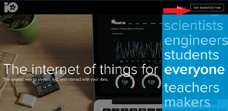
To use Adafruit IO, first, you have to create an account on Adafruit IO. To do this, go to the Adafruit IO website and click on ‘Get started for Free’ on the top right of the screen.
Why Adafruit IO for IoT Applications in Agriculture?
∗ No Cost Starting Point: Base tier with access to 30 data points a minute will support small smart farming using IoT project
∗ MQTT: The protocol that most IoT systems use to communicate, providing a reliable connection, even with spotty connectivity from the farm location.
∗ Strength in Numbers: Dashboards with drag and drop dashboard building capabilities, with gauges, the ability to see trends over time (data plotted and graphed) on historical data, and switch items on or off.
∗ REST: RESTful API for access for your own custom app, or even for agricultural software from another vendor, using the data from the project in any module you wish.
∗ Keep Data: Thirty days of historical farming data will be maintained for your trending analysis and for planting season recommendations.
Step-by-Step Adafruit IO Account Setup
⇒ Step 1: Create Your Adafruit IO Account
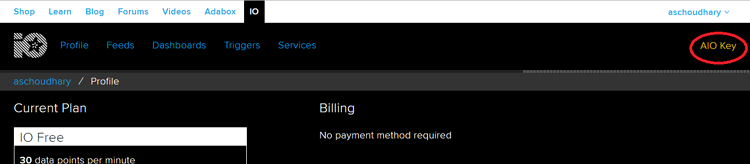
After finishing the account creation process, log in to your account and click on ‘View AIO Key’ on the top right corner to get your account username and AIO key.
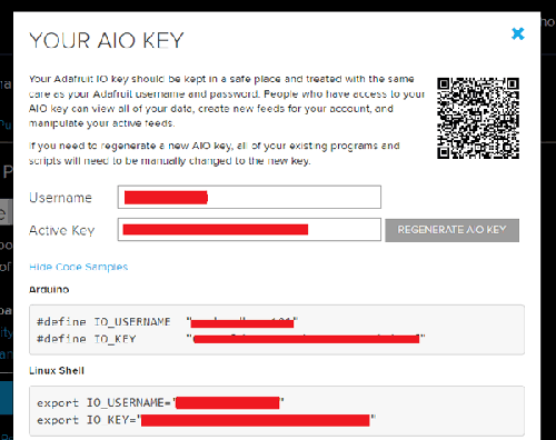
⇒ Step 2: Obtain Your AIO Key Credentials
When you click on ‘AIO Key,’ a window will pop up with your Adafruit IO AIO Key and username. Copy this key and username. You'll need it later in your code. These credentials authenticate your NodeMCU's connection to the smart agriculture using IoT cloud infrastructure.
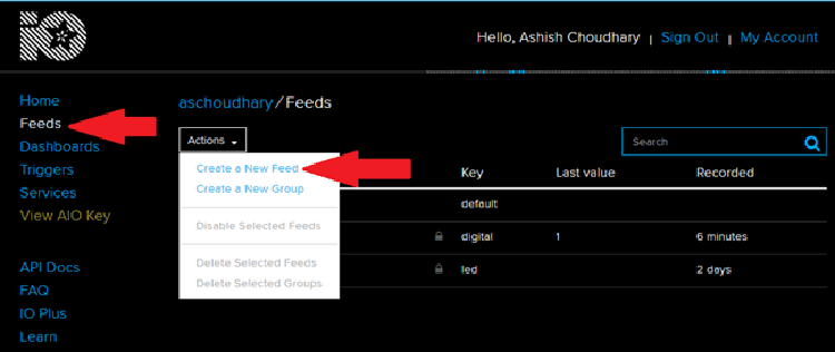
⇒ Step 3: Create Data Feeds for Agricultural Parameters
Now, after this, you need to create a feed. To create a feed, click on ‘Feed.’ Then click on ‘Actions,’ you will see some options, from them, click on ‘Create a New Feed.’ For this smart agriculture using IoT block diagram implementation, we'll create eight feeds corresponding to sensors and actuators.
After this, a new window will open where you need to input the Name and Description of your feed. Writing a description is optional.
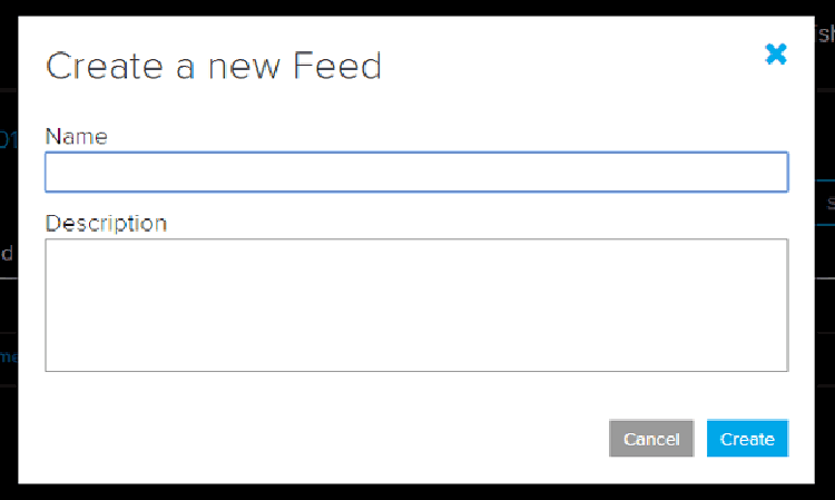
Click on ‘Create,’; after this, you will be redirected to your newly created feed.
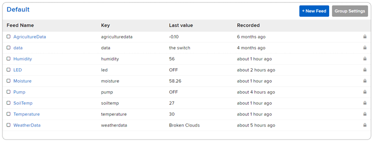
For this project, we created a total of eight feeds for Water pump, LED Strip, moisture data, Temperature, Humidity, Weather data, and Soil Temperature. Follow the same procedure as above to create the rest of the feeds.
⇒ Step 4: Build Your Smart Agriculture Dashboard
After creating feeds, we will create an Adafruit IO dashboard to show all of these feeds on a single page. For that, first create a dashboard and then add all these feeds to that dashboard. Dashboards provide visual interfaces for monitoring sensor data and controlling actuators remotely—the core functionality of smart agriculture using IoT cloud systems.
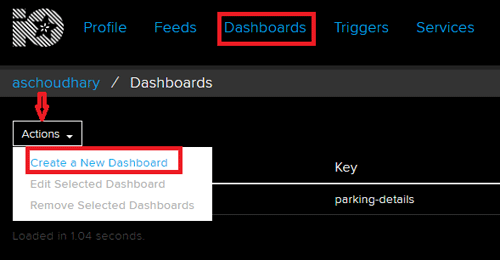
To create a dashboard, click on the Dashboard option and then click on the ‘Action,’ and after this, click on ‘Create a New Dashboard.’
In the next window, enter the name for your dashboard and click on ‘Create.’
⇒ Step 5: Add Visualisation Blocks to Dashboard
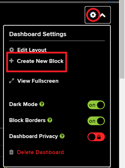
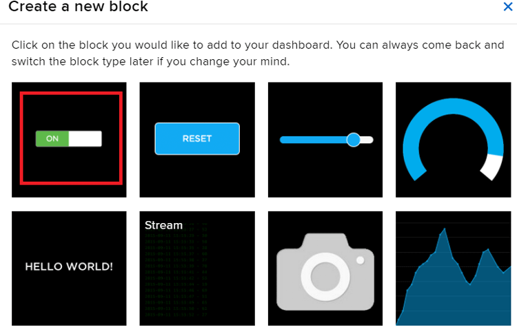
As our dashboard is created, now we will add our Blocks to the dashboard. To add a Block, click on the ‘Gear’ in the top right corner and then click on ‘Create New Block’.
First, we will add two toggle button blocks to turn ON/OFF the LED Strip and Water Pump manually, then four sliders to display Temperature, Humidity, Soil Temperature, and Moisture Value and in last, two Graph blocks to display the last 30 days of Moisture and Soil Temperature Data. To add a button on the dashboard, click on the Toggle block.
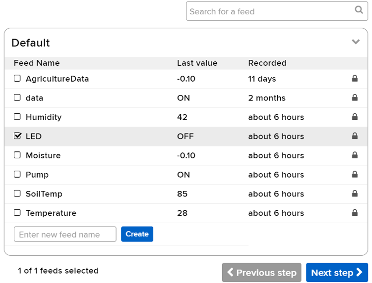
In the next window, it will ask you to choose the feed, so click on the LED feed.
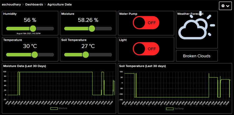
After this, follow the same procedure to add the rest of the blocks. After adding all the blocks, my dashboard looks like this:

You can edit your dashboard by clicking on the settings button. After adding all blocks, your completed dashboard provides comprehensive monitoring and control for your smart agriculture using IoT project. The dashboard is responsive and works seamlessly on desktop computers, tablets, and smartphones—enabling true remote farm management for IoT applications in agriculture.
Integrating Weather Forecasting in Smart Agriculture Using IoT
Advanced smart agriculture using IoT project implementations benefit significantly from weather prediction integration. As mentioned earlier, we are also going to display the weather forecast on the Adafruit IO dashboard, and for that, we will use the OpenWeatherMap API to request the day’s weather forecast for the chosen location. OpenWeatherMap provides highly recognisable weather products that make working with the weather data a lot easier. This data can be accessed via fast, reliable APIs that follow industry standards and are compatible with different kinds of enterprise systems. The free tier accommodates typical IoT smart agriculture requirements with 60 API calls per minute and 1,000 calls per day.
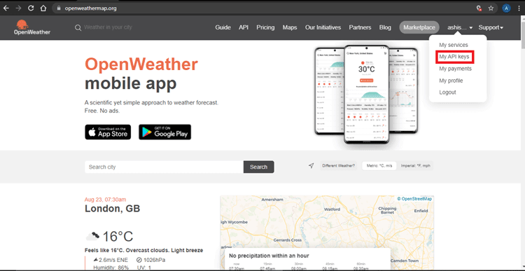
Now, to obtain the API key, it’s necessary to sign up on their platform, so first create an account, and once your account is created, you’ll be redirected to the dashboard, as shown below. From there, click on your Name and then click on ‘My API Keys’ and you will be presented with a unique API key to pull information from the site.
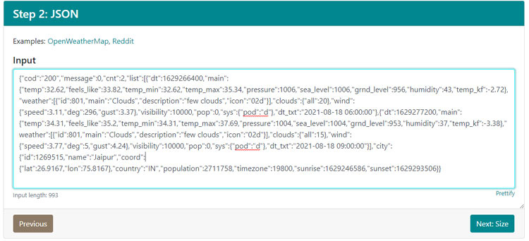
Now we are going to use a 5-day / 3-hour forecast data API. This API includes weather forecast data with a 3-hour gap, and forecast data is available in JSON or XML format. To get the weather data for your chosen location, enter the URL below with the sections in curly brackets replaced with the city and your unique API key:
api.openweathermap.org/data/2.5/forecast?q={city name}&appid={API key}For example, our API URL would be:
api.openweathermap.org/data/2.5/forecast?q=Jaipur&appid=e8b22b36da932dce8f31ec9be9cb68a3
Paste this URL into your browser’s search bar, and it should give you a bunch of information that corresponds to your local weather forecast information.

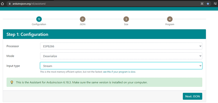
Now that we have the JSON data, the next step will be generating the code by which we can read the JSON data and phrase it according to our needs. For that, go to the ArduinoJson Assistant and in the first step select the processor type, Mode, and Input Type. For production smart agriculture using IoT cloud deployments, store keys in secure environment variables.
Then, in the next section, paste the JSON data.
Then, in the last step, you will get the code to read the weather forecast data. We will not use the complete code that is generated by the Assistant.
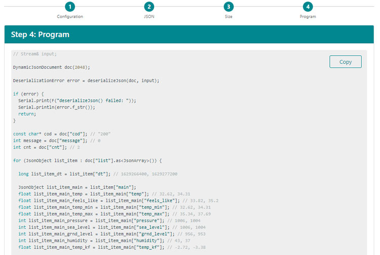
Programming NodeMCU for Smart Agriculture System Using Arduino IDE
The complete code for the IoT-based Agriculture Monitoring System is given at the end of the document. Here we are explaining some important parts of the code. The code uses the DallasTemperature, OneWire, Adafruit_MQTT, ArduinoJson, and DHT.h libraries. The Adafruit_MQTT.h and DHT11.h can be downloaded from the given links; the rest of the library can be directly downloaded from the Arduino IDE library manager.
After installing the libraries in the Arduino IDE, start the code by including the required library files.
#include <ESP8266WiFi.h>
#include <DallasTemperature.h>
#include <OneWire.h>
#include "DHT.h"
#include "Adafruit_MQTT.h"
#include "Adafruit_MQTT_Client.h"
#include <ArduinoJson.h>
Required Arduino Libraries
| Library | Version | Purpose | Installation |
| ESP8266WiFi | Built-in | WiFi connectivity for NodeMCU | Included with ESP8266 board package |
| Adafruit_MQTT | 2.5.0+ | MQTT protocol for Adafruit IO | GitHub or Library Manager |
| DHT sensor library | 1.4.4+ | DHT11 temperature & humidity | GitHub or Library Manager |
| OneWire | 2.3.7+ | OneWire protocol for DS18B20 | Library Manager |
| DallasTemperature | 3.11.0+ | DS18B20 sensor interface | Library Manager |
| ArduinoJson | 6.21.0+ | JSON parsing for weather API | Library Manager |
Then enter the Wi-Fi and Adafruit IO credentials that you copied from the Adafruit IO server. These will include the MQTT server, Port No, User Name, and AIO Key.
const char *ssid =  "Wi-Fi Name";
const char *pass =  "Wi-Fi password";
#define MQTT_SERV "io.adafruit.com"
#define MQTT_PORT 1883
#define MQTT_NAME "Adafruit IO Username"
#define MQTT_PASS "AIO Key"
Then set up the Adafruit IO feeds for storing the sensor data and controlling the LED and water pump. In my case, I have defined four feeds to store different sensor data, namely: Soil Temperature, Temperature, Humidity and Moisture, one feed for displaying Weather data and two feeds to control the LED Strip & Water Pump.
Adafruit_MQTT_Client mqtt(&client, MQTT_SERV, MQTT_PORT, MQTT_NAME, MQTT_PASS);
Adafruit_MQTT_Publish Moisture = Adafruit_MQTT_Publish(&mqtt,MQTT_NAME "/f/Moisture");
Adafruit_MQTT_Publish Temperature = Adafruit_MQTT_Publish(&mqtt,MQTT_NAME "/f/Temperature");
Adafruit_MQTT_Publish Humidity = Adafruit_MQTT_Publish(&mqtt,MQTT_NAME "/f/Humidity");
Adafruit_MQTT_Publish SoilTemp = Adafruit_MQTT_Publish(&mqtt,MQTT_NAME "/f/SoilTemp");
Adafruit_MQTT_Subscribe LED = Adafruit_MQTT_Subscribe(&mqtt, MQTT_NAME "/f/LED");
 Adafruit_MQTT_Subscribe Pump = Adafruit_MQTT_Subscribe(&mqtt, MQTT_NAME "/f/Pump");
Now inside the setup() function, initialise the Serial Monitor at a baud rate of 9600 for debugging purposes. Also, initialise the DHT sensor and DS18B20 sensor with the begin() function.
void setup()
{
  Serial.begin(9600);
  delay(10);
  dht.begin();
  sensors.begin();
………………..
}
Now comes the void loop(). This is where all the tasks are performed. So, in this loop, first we will get the weather forecast data from OpenWeatherMap API, then we will read the sensors data, and in the last step, we will publish all this data on the Adafruit IO dashboard.
Reading the Weather Forecast:
To read the weather forecast data from OpenWeatherMap API, we will use the code snippets that we generated using ArduinoJson Assistant. Here in the void loop, we will only call the API after a particular time interval so that we don’t exceed our daily limit.
if (millis() - lastConnectionTime > postInterval) {
    // note the time that the connection was made:
    lastConnectionTime = millis();
    makehttpRequest();
  }
Reading the Sensor Data:
Now, after getting the weather data, next we will read all the sensor data. Here we are using the DHT11, DS18B20, LDR and Soil Moisture Sensor. LDR and soil moisture sensor data will be used to automate the LED strip and water pump. So first we will read the LDR status and if the LDR reading is less than 200, then the LED will be turned on automatically. Similarly, if the soil moisture percentage is less than 35, then the water pump will be turned on.
int ldrStatus = analogRead(ldrPin);
    if (ldrStatus <= 200) {
       digitalWrite(ledPin, HIGH);
    }
    else {
      digitalWrite(ledPin, LOW);     }
  moisturePercentage = ( 100.00 - ( (analogRead(moisturePin) / 1023.00) * 100.00 ) );
if (moisturePercentage < 35) {
  digitalWrite(motorPin, HIGH);
}
temperature = dht.readTemperature();
 humidity = dht.readHumidity();
sensors.requestTemperatures();
soiltemp = sensors.getTempCByIndex(0);
Publishing the Data on Adafruit IO:
Now that we have collected all the data, it's time to publish this data on the Adafruit IO dashboard, so that we can monitor it from anywhere. Here we will publish the different sensor data to their respective feeds. Download, customise WiFi/Adafruit IO credentials, and upload to your NodeMCU to begin monitoring your smart agriculture using IoT system.
 if (currentTime - previousTime >= Interval) {
    if (! Moisture.publish(moisturePercentage))
    if (! Temperature.publish(temperature))
    if (! Humidity.publish(humidity))
    if (! SoilTemp.publish(soiltemp))
    if (! WeatherData.publish(icon))
}
Technical Summary and GitHub Repository
A comprehensive overview of the project’s engineering structure and implementation details is presented here, along with the GitHub repository for transparent access to the development workflow. All source code, 3D printable files, circuit diagrams, and supplementary documentation for this smart agriculture using IoT project are openly available on GitHub.


3D Printed Weatherproof Enclosure for Smart Agriculture Using IoT
Field deployment of IoT applications in agriculture requires weatherproof enclosures to protect electronics from moisture, dust, and temperature extremes. This section documents the custom 3D-printed housing designed specifically for this smart agriculture system using Arduino-compatible NodeMCU.As this project will be used in farming applications, I decided to 3D print an enclosure. I measured the dimensions of the setup using a vernier to design a casing. Once it was done, my design looked something like this:
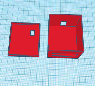
After I was satisfied with the design, I exported it as an STL file, sliced it based on printer settings, and finally printed it. The STL file is also available for download from Thingiverse, and you can print your own casing using it.
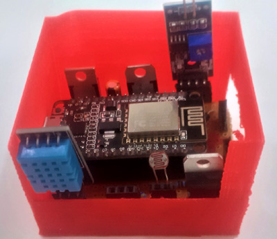
After the print was done, I proceeded with assembling the project setup in a permanent enclosure for future use. Once the complete connection was done, I assembled the circuit into my casing, and everything was nicely fit as you can see below:
Testing and Validation of IoT Smart Agriculture System
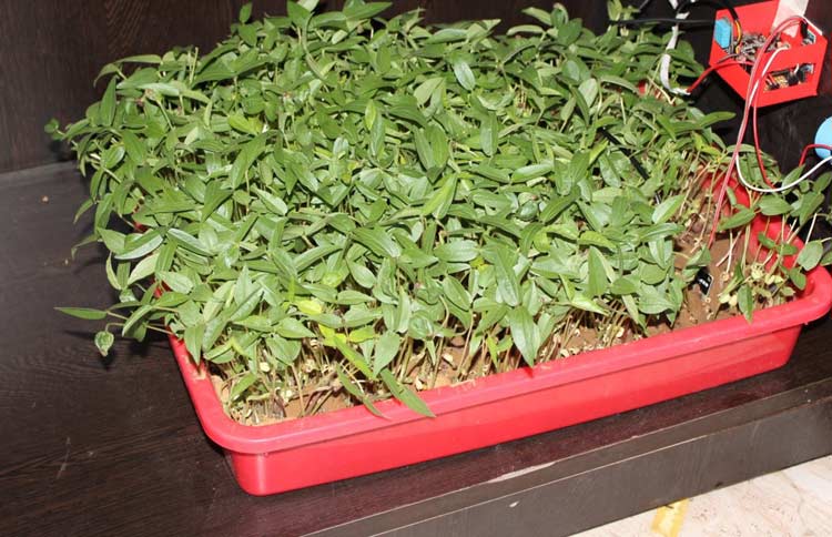
After completing hardware assembly, software configuration, and enclosure installation, the final phase involves comprehensive field testing to validate all smart agriculture using IoT functionality. This section documents the testing methodology and real-world performance results. To test this project, I sprouted some seeds in a plastic tray as shown in the image below:
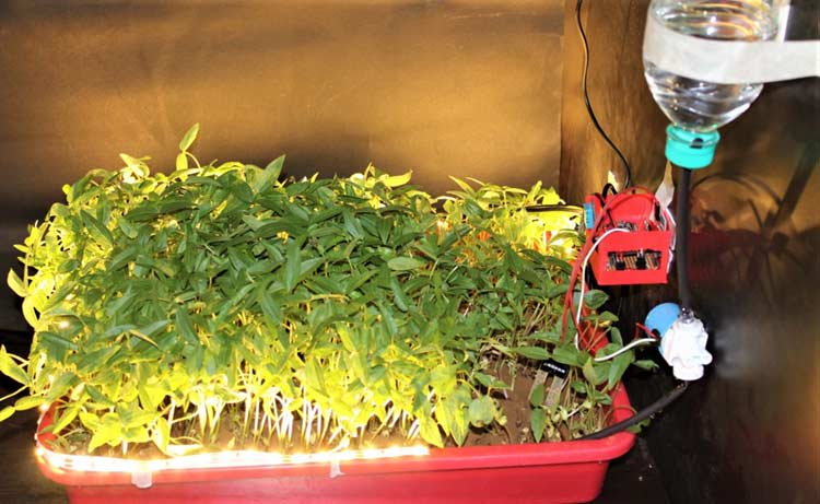
I mounted the hardware box beside the tray, connected a water pump to a water bottle, and connected the power supply. With this done, it starts monitoring the different parameters like soil moisture, soil temperature, etc. All these readings will be published on the Adafruit IO dashboard.
Future Enhancements for IoT Applications in Agriculture
Multidimensional Expansion: Add a pH sensor, NPK sensor (nitrogen, phosphorus, potassium), and EC (electrical conductivity) meter to provide a complete soil analysis
Camera Addition: The ESP32-CAM module is able to do time-lapse photos and employ AI to automatically recognise invasive species.
Drip Irrigation: Employ a solenoid valve with drip lines and eliminate the pump to properly distribute water more effectively on row crops.
Solar: Allow the system to be off-grid using a solar panel that is 20W, a 12V 7Ah battery, and a PWM charge controller.
LoRa: Use LoRaWAN to transfer data at over 1 kilometre on large farms that do not have cellular communication
Machine Learning: Use past data to analyse and use TensorFlow Lite to make predictive recommendations for irrigation.
Mobile App: Create a custom mobile app on Android/iOS using the Adafruit IO API to allow a branded user interaction.
Frequently Asked Questions - Smart Agriculture Using IoT
⇥ 1. Is it possible to utilise Arduino instead of NodeMCU for smart farming?
Yes! You could make a smart farming system with Arduino; however, you will need a separate WiFi module (ESP8266 or ESP32 shield) to connect with IoT. NodeMCU is generally recommended as it has built-in WiFi, it is inexpensive, and it is fully Arduino compatible, which is convenient for smart farming with IoT.
⇥ 2. What are the best IoT use cases for farming?
Based on the use case of IoT in agriculture, the best applications are automated drip irrigation systems, monitoring soil health, advisory for crop care based on inclusive weather information, GPS-collared livestock tracking, drone surveillance for pest detection, greenhouse climate control, and predictive times to harvest. These applications have reduced costs by 30% and have increased output exponentially!
⇥ 3. What is the method of the IoT cloud-based smart agriculture system?
IoT cloud-based smart agriculture uses the Internet and online platforms like Adafruit IO, ThingSpeak, or AWS IoT to store and visualise data. By using their mobile phones or computers, the farmers can access the live dashboards from any place and at any time. Cloud computing is significant in the process of making data useful information through data analysis, historical trends, and enabling the remote control of irrigation systems and hardware.
⇥ 4. How much does it cost to implement an IoT smart agriculture system?
A basic DIY smart agriculture using IoT project may cost $25-50 for components (NodeMCU, sensors, pump). In contrast, commercially available IoT smart agriculture systems range from $200-2000, depending on the size of the farm and functional capabilities. Free cloud program platforms such as Adafruit IO are also available for small-scale operations, making entry-level implementation very affordable.
⇥ 5. Can smart agriculture be understood by means of an IoT block diagram?
A smart agro IoT block diagram displays five levels: Sensor Layer-data gathering, Processing microcontroller logic, Communication Layer-WiFi/MQTT, Cloud Layer-data storage/visualisation, and Actuator Layer-pump/LED control. The different blocks are functional components, and they help data flow to the farmer's dashboard from the field easy to understand.
⇥ 6. Which sensors apply to smart agriculture using IoT devices?
The sensors commonly recognised for smart agriculture are soil moisture sensors (capacitive/resistive), DHT11/DHT22 for temperature and humidity, waterproof probes (DS18B20) for soil temperature, pH sensors, NPK sensors for soil nutrients reading, light sensors (LDR), rain sensors, and CO2 sensors for a greenhouse setting. Multiple sensors provide a complete monitoring experience in crop environments.
⇥ 7. What programming language is used for the IoT project for smart agriculture?
The programming of any smart agriculture set on a NodeMCU/Arduino will use C/C++ programming languages using the Arduino IDE environment. A programming code invokes a library of code, such as <DHT.h>, <OneWire>, <DallasTemperature>, and <Adafruit_MQTT>. For the Raspberry Pi system, Python is another language commonly selected. When using NodeMCU/Arduino or Raspberry Pi, some basic knowledge of programming and interfacing a sensor is needed to implement the project.
Conclusion
This comprehensive guide demonstrates how accessible and affordable smart agriculture using IoT technology has become for home gardeners, small-scale farmers, and agricultural educators. With less than $40 in components and basic Arduino programming skills, anyone can deploy a professional-grade monitoring and automation system.
We hope this smart agriculture using IoT project inspires you to explore precision farming technologies and contribute to sustainable food production. Beyond monitoring parameters, you can extend this foundation to control greenhouse ventilation, manage aquaponics systems, or automate vertical farming operations.
So, this is how you can set up an IoT-based smart Agriculture System. Apart from these parameters, you can also measure some other parameters like PH, etc. Hope you enjoyed the project and learned something useful. If you have any questions, please leave them in the comment section below or use our forum to start a discussion on this.
Smart IoT Systems for Soil, Sewage & Weather Monitoring
A set of IoT-based systems that monitor soil moisture, sewage levels, and weather conditions using sensors and microcontrollers. These smart solutions enable real-time data tracking and efficient environmental management.

How to Build an IoT-based Weather Monitoring System Using Arduino?
This DIY IoT Weather Station project only requires a few environmental sensors and the versatile Arduino UNO R4 WiFi board. It blends IoT, web development, and embedded programming, making it an ideal IoT project for beginners, students, and tech enthusiasts interested in smart weather systems, Arduino projects, and real-time data monitoring.

Sewage Monitoring and Maintenance Alert using IoT
In this article, we are going to build a smart device that can sense when the drainage system gets blocked and if the water overflows because of this blockage, we will send a notification to the municipal authority for the necessary action.

Low Power IoT Based Compact Soil Moisture Monitoring Device
In this project, we will build a low-cost connected solution with a pre-designed Soil monitor using different components. This elegant project design was made possible by the PCB boards fabricated by PCBWay, we will also show you how the board was designed and ordered from PCBway.
Complete Project Code
#include <ESP8266WiFi.h>
#include <DallasTemperature.h>
#include <OneWire.h>
#include "DHT.h"
#include "Adafruit_MQTT.h"
#include "Adafruit_MQTT_Client.h"
#include <ArduinoJson.h>
const char *ssid =  "Galaxy-M20";     // Enter your WiFi Name
const char *pass =  "ac312124"; // Enter your WiFi Password
WiFiClient client;
#define MQTT_SERV "io.adafruit.com"
#define MQTT_PORT 1883
#define MQTT_NAME "aschoudhary" // Your Adafruit IO Username
#define MQTT_PASS "1ac95cb8580b4271bbb6d9f75d0668f1" // Adafruit IO AIO key
const char server[] = "api.openweathermap.org";
String nameOfCity = "Jaipur,IN";
String apiKey = "e8b22b36da932dce8f31ec9be9cb68a3";
String text;
const char* icon="";
int jsonend = 0;
boolean startJson = false;
int status = WL_IDLE_STATUS;
#define JSON_BUFF_DIMENSION 2500
unsigned long lastConnectionTime = 10 * 60 * 1000;     // last time you connected to the server, in milliseconds
const unsigned long postInterval = 10 * 60 * 1000;  // posting interval of 10 minutes  (10L * 1000L; 10 seconds delay for testing)
const int ldrPin = D1;
const int ledPin = D0;
const int moisturePin = A0;  // moisteure sensor pin
const int motorPin = D8;
float moisturePercentage;              //moisture reading
int temperature, humidity, soiltemp;
#define ONE_WIRE_BUS 4   //D2 pin of nodemcu
#define DHTTYPE DHT11   // DHT 11
#define dht_dpin D4
DHT dht(dht_dpin, DHTTYPE);
OneWire oneWire(ONE_WIRE_BUS);
DallasTemperature sensors(&oneWire);
const unsigned long Interval = 50000;
unsigned long previousTime = 0;
//Set up the feed you're publishing to
Adafruit_MQTT_Client mqtt(&client, MQTT_SERV, MQTT_PORT, MQTT_NAME, MQTT_PASS);
Adafruit_MQTT_Publish Moisture = Adafruit_MQTT_Publish(&mqtt,MQTT_NAME "/f/Moisture");  // Moisture is the feed name where you will publish your data
Adafruit_MQTT_Publish Temperature = Adafruit_MQTT_Publish(&mqtt,MQTT_NAME "/f/Temperature");
Adafruit_MQTT_Publish Humidity = Adafruit_MQTT_Publish(&mqtt,MQTT_NAME "/f/Humidity");
Adafruit_MQTT_Publish SoilTemp = Adafruit_MQTT_Publish(&mqtt,MQTT_NAME "/f/SoilTemp");
Adafruit_MQTT_Publish WeatherData = Adafruit_MQTT_Publish(&mqtt,MQTT_NAME "/f/WeatherData");
//Set up the feed you're subscribing to
 Adafruit_MQTT_Subscribe LED = Adafruit_MQTT_Subscribe(&mqtt, MQTT_NAME "/f/LED");
 Adafruit_MQTT_Subscribe Pump = Adafruit_MQTT_Subscribe(&mqtt, MQTT_NAME "/f/Pump");
void setup()
{
  Serial.begin(9600);
  delay(10);
  dht.begin();
  sensors.begin();
  mqtt.subscribe(&LED);
  mqtt.subscribe(&Pump);
  pinMode(motorPin, OUTPUT);
  pinMode(ledPin, OUTPUT);
  pinMode(ldrPin, INPUT);
  digitalWrite(motorPin, LOW); // keep motor off initally
  digitalWrite(ledPin, HIGH);
  text.reserve(JSON_BUFF_DIMENSION);
  Serial.println("Connecting to ");
  Serial.println(ssid);
  WiFi.begin(ssid, pass);
  while (WiFi.status() != WL_CONNECTED)
  {
    delay(500);
    Serial.print(".");              // print ... till not connected
  }
  Serial.println("");
  Serial.println("WiFi connected");
}
void loop()
{
 unsigned long currentTime = millis();
 MQTT_connect();
 if (millis() - lastConnectionTime > postInterval) {
    // note the time that the connection was made:
    lastConnectionTime = millis();
    makehttpRequest();
  }
//}
 int ldrStatus = analogRead(ldrPin);
    if (ldrStatus <= 200) {
       digitalWrite(ledPin, HIGH);
       Serial.print("Its DARK, Turn on the LED : ");
       Serial.println(ldrStatus);
    }
    else {
      digitalWrite(ledPin, LOW);
      Serial.print("Its BRIGHT, Turn off the LED : ");
      Serial.println(ldrStatus);
     }
  moisturePercentage = ( 100.00 - ( (analogRead(moisturePin) / 1023.00) * 100.00 ) );
  Serial.print("Soil Moisture is  = ");
  Serial.print(moisturePercentage);
  Serial.println("%");
if (moisturePercentage < 35) {
  digitalWrite(motorPin, HIGH);         // tun on motor
}
if (moisturePercentage > 38) {
  digitalWrite(motorPin, LOW);          // turn off mottor
}
 temperature = dht.readTemperature();
 humidity = dht.readHumidity();
 //Serial.print("Temperature: ");
 //Serial.print(temperature);
 //Serial.println();
 //Serial.print("Humidity: ");
 //Serial.print(humidity);
 //Serial.println();
 sensors.requestTemperatures();
 soiltemp = sensors.getTempCByIndex(0);
// Serial.println("Soil Temperature: ");
// Serial.println(soiltemp);
if (currentTime - previousTime >= Interval) {
    if (! Moisture.publish(moisturePercentage)) //This condition is used to publish the Variable (moisturePercentage) on adafruit IO. Change thevariable according to yours.
         {
            }
    if (! Temperature.publish(temperature))
         {
           }
    if (! Humidity.publish(humidity))
         {
         //delay(30000);
          }
    if (! SoilTemp.publish(soiltemp))
       {
          }
    if (! WeatherData.publish(icon))
       {
         }
          previousTime = currentTime;
}
Adafruit_MQTT_Subscribe * subscription;
while ((subscription = mqtt.readSubscription(5000))) //Dont use this one until you are conrolling something or getting data from Adafruit IO.
     {
    if (subscription == &LED)
     {
      //Print the new value to the serial monitor
      Serial.println((char*) LED.lastread);
        if (!strcmp((char*) LED.lastread, "OFF"))
       {
         digitalWrite(ledPin, LOW);
        }
        if (!strcmp((char*) LED.lastread, "ON"))
          {
         digitalWrite(ledPin, HIGH);
         }
     }
    if (subscription == &Pump)
      {
      //Print the new value to the serial monitor
      Serial.println((char*) Pump.lastread);

      if (!strcmp((char*) Pump.lastread, "OFF"))
       {
        digitalWrite(motorPin, HIGH);
       }
     if (!strcmp((char*) Pump.lastread, "ON"))
       {
        digitalWrite(motorPin, LOW);
       }
     }
    }
  delay(9000);
 // client.publish(WeatherData, icon)
}
void MQTT_connect()
{
  int8_t ret;
  // Stop if already connected.
  if (mqtt.connected())
  {
    return;
  }
  uint8_t retries = 3;
  while ((ret = mqtt.connect()) != 0) // connect will return 0 for connected
  {
       mqtt.disconnect();
       delay(5000);  // wait 5 seconds
       retries--;
       if (retries == 0)
       {
         // basically die and wait for WDT to reset me
         while (1);
       }
  }
}
void makehttpRequest() {
  // close any connection before send a new request to allow client make connection to server
  client.stop();
  // if there's a successful connection:
  if (client.connect(server, 80)) {
    client.println("GET /data/2.5/forecast?q=" + nameOfCity + "&APPID=" + apiKey + "&mode=json&units=metric&cnt=2 HTTP/1.1");
    client.println("Host: api.openweathermap.org");
    client.println("User-Agent: ArduinoWiFi/1.1");
    client.println("Connection: close");
    client.println();
    unsigned long timeout = millis();
    while (client.available() == 0) {
      if (millis() - timeout > 5000) {
        Serial.println(">>> Client Timeout !");
        client.stop();
        return;
      }
    }
    char c = 0;
    while (client.available()) {
      c = client.read();
      // since json contains equal number of open and close curly brackets, this means we can determine when a json is completely received  by counting
      // the open and close occurences,
      //Serial.print(c);
      if (c == '{') {
        startJson = true;         // set startJson true to indicate json message has started
        jsonend++;
      }
      if (c == '}') {
        jsonend--;
      }
      if (startJson == true) {
        text += c;
      }
      // if jsonend = 0 then we have have received equal number of curly braces
      if (jsonend == 0 && startJson == true) {
        parseJson(text.c_str());  // parse c string text in parseJson function
        text = "";                // clear text string for the next time
        startJson = false;        // set startJson to false to indicate that a new message has not yet started
      }
    }
  }
  else {
    // if no connction was made:
    Serial.println("connection failed");
    return;
  }
}
//to parse json data recieved from OWM
void parseJson(const char * jsonString) {
  //StaticJsonBuffer<4000> jsonBuffer;
  const size_t bufferSize = 2*JSON_ARRAY_SIZE(1) + JSON_ARRAY_SIZE(2) + 4*JSON_OBJECT_SIZE(1) + 3*JSON_OBJECT_SIZE(2) + 3*JSON_OBJECT_SIZE(4) + JSON_OBJECT_SIZE(5) + 2*JSON_OBJECT_SIZE(7) + 2*JSON_OBJECT_SIZE(8) + 720;
  DynamicJsonBuffer jsonBuffer(bufferSize);
//  DynamicJsonDocument(bufferSize);
  // FIND FIELDS IN JSON TREE
  JsonObject& root = jsonBuffer.parseObject(jsonString);
  if (!root.success()) {
    Serial.println("parseObject() failed");
    return;
  }
  JsonArray& list = root["list"];
  JsonObject& nowT = list[0];
  JsonObject& later = list[1];
  JsonObject& tommorow = list[2];
//  String conditions = list.weather.main;
  // including temperature and humidity for those who may wish to hack it in
  String city = root["city"]["name"];
  String weatherNow = nowT["weather"][0]["description"];
  String weatherLater = later["weather"][0]["description"];
  String list12 = later["weather"][0]["list"];
  Serial.println(list12);
  Serial.println(weatherLater);
  if(weatherLater == "few clouds"){
    icon = "Few Clouds";
    Serial.print(icon);
  }
  else if(weatherLater == "rain"){
    icon = "Rain";
    Serial.print(icon);
  }
  else if(weatherLater == "broken clouds"){
    icon = "Broken Clouds";
    Serial.print(icon);
  }
  else {
    icon = "Sunny";
    }
}
Comments
Awesome description about this project. I love the way you describe this.
Hello,
I am residing in Melbourne, Australia. While I am entering the link to obtain the weather data it's saying invalid, I think that link is permitted only to cities in India. Now how to grab the info? if possible, could you give me the link that suits Australia.
doubt 2. you said you are using Dallas temperature what does that mean? as you are grabbing info about Jaipur and using Dallas. I am confused here.
could you please clarify these two doubts?
thanks
Can I get hardware components connection video

can i get this project ppts n synopsis sir....