
In this project, we'll explore an IoT-based irrigation system using the ESP32 board and Blynk app. It's a project based on the Internet of Things (IoT), the smart irrigation system offers numerous possibilities to automate the entire irrigation process. Here, we're creating a plot-based smart irrigation system using the ESP32 Controller, a soil moisture sensor, a water level sensor, a relay module and DHT22 Sensor. It will send data to the new Blynk application to monitor the land condition. The system includes a water pump that sprinkles water based on the land's conditions, considering factors like moisture, temperature, and humidity. This system is handy for farms and greenhouses.
We previously built a similar Automatic Plant Irrigation System which sends alerts on mobile but not on IoT cloud. Apart from this, Rain alarm and soil moisture detector circuit can also be helpful in building Smart Irrigation systems.
Also, we have built an Advanced IoT based Soil Moisture Monitoring Device, you can check out the demonstration video given below.
How does our Smart Irrigation System work?
We will use Capacitive Soil Moisture Sensor to measure moisture content present in the soil. You can also use a resistive soil moisture sensor. and we use a water level sensor to measure water level inside the water tank. Similarly, to measure Air Temperature and Humidity, we prefer the DHT22 Humidity Temperature Sensor. Using a 5V Power relay we will control the Water Pump. When powered ON this system, the ESP32 board connects to the Blynk app using the internet and Blynk cloud. Then, the soil moisture values are displayed on the Blynk app interface. Whenever the sensor detects a low quantity (less than 50%) of moisture in the soil, the motor turns on automatically. Hence, will automatically irrigate the field. If the water sensor detects low water level (less than 20%) inside the water tank in this case the motor will not turn on automatically. Once the soil becomes wet, the motor turns off. Also, with the button created in this Blynk app, we can turn the relay module ON and OFF manually in manual mode. You can monitor all this happening remotely via blynk App from any part of the world.
Required Components for the ESP32 Smart Irrigation System
ESP32 Board
Capacitive soil Moisture Sensor
Water level sensor
DHT22
Water Pump
Relay Module
3.7 V Li-ion Battery
5V RGB led Strip
Connecting Wires
Capacitive Soil Moisture Sensor
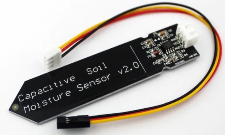
This sensor is an analog capacitive soil moisture sensor that measures soil moisture levels through capacitive sensing. The sensor adjusts its capacitance based on the amount of water in the soil. You can translate this capacitance variation into a voltage level, ranging from a minimum of 1.2V to a maximum of 3.0V. One of the benefits of the Capacitive Soil Moisture Sensor is its construction from corrosion-resistant materials, ensuring a prolonged service life.
DHT22 Humidity Temperature Sensor
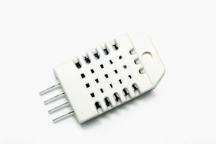
The DHT11 is a basic and very cheap sensor that measures both temperature and humidity. It uses a special sensor to find out how much humidity is in the air and a temperature sensor to measure the temperature. The sensor gives us this information in a digital way through a single wire. It's easy to use, but we need to be patient because it takes about 2 seconds to get new information. In our project, we'll use this sensor to tell us how hot and humid the air is.
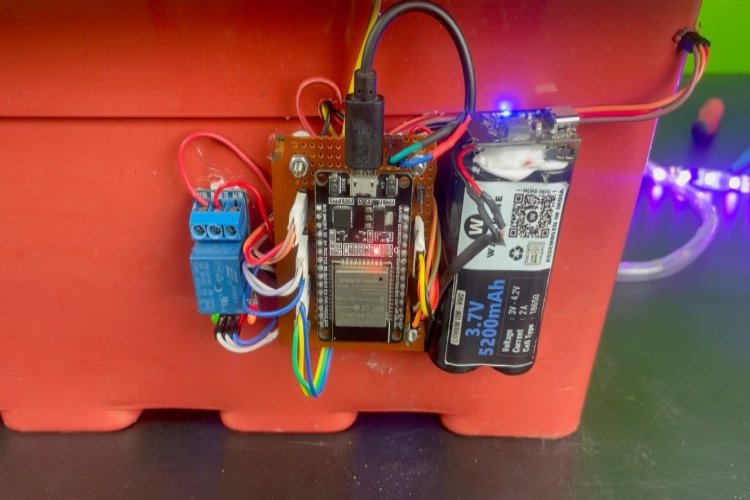
Circuit Diagram of the ESP32 Smart Irrigation System
Circuit diagram for this IoT Smart Irrigation System is given below.

Connect the soil moisture sensor to D35 pin of ESP32, water level sensor to D34 pin and DHT22 to D4 Pin. The motor connects to Relay. To control the relay, we use the D5 Pin of ESP32. Connect the RGB LED strip to the D21 pin of ESP32. You can power the Motor and Relay using the 3.7V from the Li-ion battery. The DHT22 Sensor, Capacitive Soil Moisture Sensor, and Water level sensor requires a 3.3V Supply only.
Blynk App Setup
Now, we created the New Blynk Application.
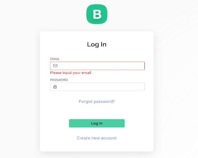
After creating the account, please visit https://blynk.io. Then enter the email id and password, and click on login.
First you have to create New Template in the Blynk App.
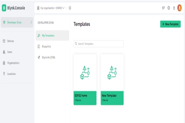
For creating a New Template in Blynk App account, follow the following steps. Goto Developer Zone in the left side menu. Click on the My Template menu. Create a new template.
From the Widgets menu you can add the Button Widgets and Gauge Widgets to the interface. Then, name it as you like and select the virtual pin as V0. Next, change the values from 1 to 0 and change the mode as the switch for Gauge widgets change the input values from 0 to 100. Finally, customize these widgets as you like.
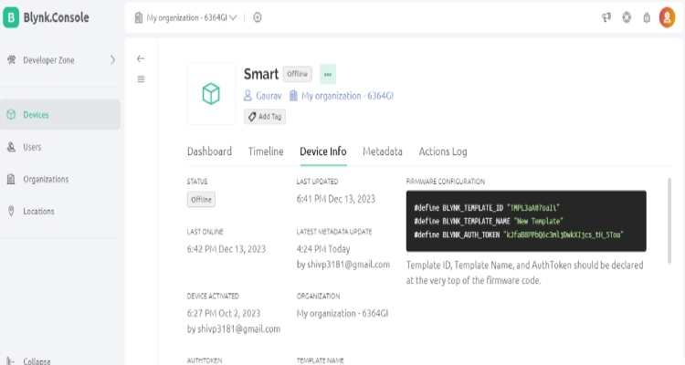
In device info you find your Template ID, Template Name, and AuthToken, copy and paste into the code.
ESP32 Smart Irrigation System Code Explanation
This code combinations of IoT, RGB LED Strip animation, and sensors like DHT22, soil moisture sensor and water level sensor, controlled and monitored through Blynk. The pump and Indication Led are controlled based on soil moisture and water level. Additionally, there are functions for changing color palettes and other visual effects of RGB LED Strip.
#define BLYNK_TEMPLATE_ID   "Replace your BLYNK_TEMPLATE_ID here"
#define BLYNK_TEMPLATE_NAME "Replace your BLYNK_TEMPLATE_NAME here"
#define BLYNK_AUTH_TOKEN    "Replace your BLYNK_AUTH_TOKEN here"
#define BLYNK_PRINT Serial
These lines define the Blynk template ID, template name, authentication token, and configure the serial output for Blynk.
#include <WiFi.h>
#include <BlynkSimpleEsp32.h>
#include "DHT.h"
#include <FastLED.h>
char auth[] = BLYNK_AUTH_TOKEN;
char ssid[] = "Wifi Name";
char pass[] = "Wifi Password";
This section includes necessary libraries (WiFi, Blynk, DHT, FastLED) and defines the authentication details and Wi-Fi credentials.
#define LED_PIN     21
#define BRIGHTNESS  255
#define LED_TYPE    WS2811
#define COLOR_ORDER GRB

const uint8_t kMatrixWidth  = 16;
const uint8_t kMatrixHeight = 16;
const bool    kMatrixSerpentineLayout = true;
Configures LED matrix parameters, such as pin, brightness, type, order, and layout.
#define DHTPIN 4
#define DHTTYPE DHT22

DHT dht(DHTPIN, DHTTYPE);
const int soilMoisturePin = 35; // Analog pin for the soil moisture sensor
const int waterLevelPin = 34;   // Analog pin for the water level sensor
const int ledPin = 2;
Configures the DHT sensor and defines pins for soil moisture, water level and LEDs.
// Constants for soil moisture thresholds
const int SOIL_MOISTURE_LOW = 50;  // Adjusted to match the 0-100 range
const int SOIL_MOISTURE_HIGH = 50; // Adjusted to match the 0-100 range

const int pumpPin = 5;  // Change this to the actual pin connected to the DC pump on ESP32
int pumpState = LOW;    // Initialize pumpState to LOW (off)
int pumpMode = 0;       // 0 for automatic, 1 for manual

int waterLevel = 0;     // Water level indicator value
unsigned long previousMillis = 0;
const unsigned long interval = 1000; // Interval in milliseconds
Sets the thresholds for soil moisture, pump pins, and variables related to pump control and water level.
void setup() {
  Serial.begin(115200);
  digitalWrite(pumpPin,LOW);
  pinMode(ledPin, OUTPUT);
  pinMode(pumpPin, OUTPUT);
  dht.begin();
  Blynk.begin(auth, ssid, pass);
  Blynk.virtualWrite(V2, LOW);
  Blynk.virtualWrite(V3, "LED OFF");
  Blynk.virtualWrite(V6, LOW); // Initialize the mode button to automatic mode
  Blynk.virtualWrite(V5, LOW); // Initialize the pump button to OFF and On
  Blynk.virtualWrite(V8, LOW); // Initialize the RGB Led Strip button to OFF And On
  delay(3000);
  LEDS.addLeds<LED_TYPE,LED_PIN,COLOR_ORDER>(leds,80);
  LEDS.setBrightness(BRIGHTNESS);
}
Initializes serial communication, output pins, Blynk connection, and LED matrix.
BLYNK_WRITE(V5) { // This function is called when the pump button state changes (Manual Control)
  if (pumpMode == 1) { // Check if the mode is manual
    pumpState = param.asInt(); // Read the state of the pump button (0 for OFF, 1 for ON)
    digitalWrite(pumpPin, pumpState); // Turn the pump on or off based on button state
  }
}

BLYNK_WRITE(V6) { // This function is called when the mode button state changes
  pumpMode = param.asInt(); // Read the state of the mode button (0 for automatic, 1 for manual)
}

BLYNK_WRITE(V8) {
  int value = param.asInt();
  if (value == 1) {
    // Turn on the LED strip and start the animation
    ledStripOn = true;
  } else {
    // Turn off the LED strip
    ledStripOn = false;
    // You can also add code to clear the LED strip here if needed
  }
}
Functions triggered by Blynk app interactions, controlling pump, Mode (Automatic & Manual) and RGB LED strip.
void loop() {
  Blynk.run();
  timer.run();

  updateLEDStrip();
  unsigned long currentMillis = millis();

  if (currentMillis - previousMillis >= interval) {
    previousMillis = currentMillis;

    // Read soil moisture or water level based on the flag
    if (pumpMode == 0) {
      int soilSensorValue = analogRead(soilMoisturePin);
      Serial.println(soilSensorValue);
      mappedSoilMoisture = map(soilSensorValue, 1023, 2750, 100, 0); // Update mappedSoilMoisture
      autoControlPump(mappedSoilMoisture); // Automatically control the pump based on soil moisture if in automatic mode
    }
If the system is in automatic mode (pumpMode == 0), it reads the soil moisture level using the soil moisture sensor. The sensor value is mapped to a range between 0 and 100, and the autoControlPump function is called to control the pump based on soil moisture.
  // Read water level
    waterLevel = analogRead(waterLevelPin);
    Serial.println(waterLevel);
    if (waterLevel < 450) {
      waterLevel = 0; // Set water level to 0 if below a threshold
    } else {
      waterLevel = map(waterLevel, 1200, 1600, 0, 100); // Map water level to 0-100
    }
Reads the water level from the water level sensor. If the water level is below a threshold (450), it sets the water level to 0. Otherwise, it maps the water level value to a range between 0 and 100.
    // Control LED
    controlLED(mappedSoilMoisture);

    // Read and send sensor data
    readAndSendSensorData();
    Blynk.virtualWrite(V7, waterLevel); // Send water level to Blynk
  }
}
Calls the controlLED function to control the LED based on the mapped soil moisture level. Then, it calls the readAndSendSensorData function to read temperature and humidity from the DHT sensor and send the data to the Blynk app. Additionally, it sends the water level to Blynk.
Testing of ESP32 Smart Irrigation Project
This water pump is designed to be fully submerged in water. The outlet pipe is strategically placed in a field for irrigation.
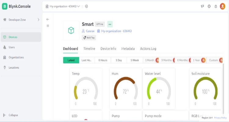
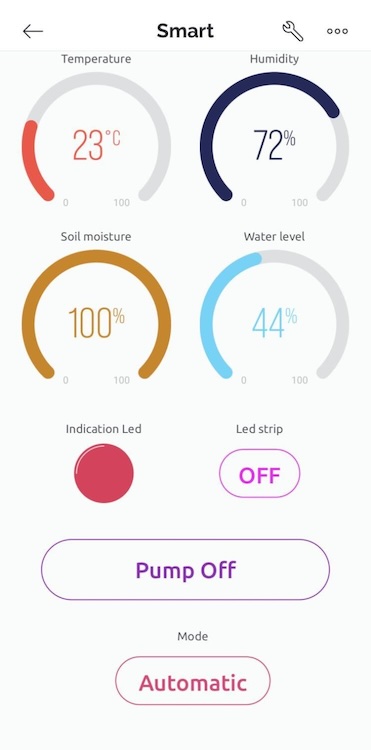
The soil moisture sensor is inserted into the soil, and similarly, the water level sensor is submerged into the water tank. Upon powering on the device and opening the Blynk App, the ESP32 automatically connects to your Wi-Fi, providing real-time data on Soil Moisture, Water Level, Air Humidity, and Air Temperature directly on the Blynk App.
In Automatic mode, if the soil moisture content decreases, the water pump activates automatically, irrigating the field until the desired moisture level is reached. Meanwhile, in Manual mode, you have the flexibility to control the pump manually, turning it on or off at your convenience. For a visual demonstration of its complete functionality, you can refer to the detailed working showcased in the video below.


Complete Project Code
//ESP32 smart irrigation code
#define BLYNK_TEMPLATE_ID    "Replace your BLYNK_TEMPLATE_ID here"
#define BLYNK_TEMPLATE_NAME  "Replace your BLYNK_TEMPLATE_NAME here"
#define BLYNK_AUTH_TOKEN     "Replace your BLYNK_AUTH_TOKEN here"
#define BLYNK_PRINT Serial
#include <WiFi.h>
#include <BlynkSimpleEsp32.h>
#include "DHT.h"
#include <FastLED.h>
char auth[] = BLYNK_AUTH_TOKEN;
char ssid[] = "Wifi Name";
char pass[] = "Wifi Password";
#define LED_PIN     21
#define BRIGHTNESS  255
#define LED_TYPE    WS2811
#define COLOR_ORDER GRB
const uint8_t kMatrixWidth  = 16;
const uint8_t kMatrixHeight = 16;
const bool    kMatrixSerpentineLayout = true;
#define NUM_LEDS (kMatrixWidth * kMatrixHeight)
#define MAX_DIMENSION ((kMatrixWidth>kMatrixHeight) ? kMatrixWidth : kMatrixHeight)
// The leds
CRGB leds[kMatrixWidth * kMatrixHeight];
BlynkTimer timer;
bool ledStripOn = false;
// The 16 bit version of our coordinates
static uint16_t x;
static uint16_t y;
static uint16_t z;

uint16_t speed = 20; // speed is set dynamically once we've started up
uint16_t scale = 30; // scale is set dynamically once we've started up
uint8_t noise[MAX_DIMENSION][MAX_DIMENSION];
CRGBPalette16 currentPalette( PartyColors_p );
uint8_t       colorLoop = 1;
#define DHTPIN 4
#define DHTTYPE DHT22
DHT dht(DHTPIN, DHTTYPE);
const int soilMoisturePin = 35; // Analog pin for the soil moisture sensor
const int waterLevelPin = 34;   // Analog pin for the water level sensor
const int ledPin = 2;

// Constants for soil moisture thresholds
const int SOIL_MOISTURE_LOW = 50;  // Adjusted to match the 0-100 range
const int SOIL_MOISTURE_HIGH = 50; // Adjusted to match the 0-100 range
const int pumpPin = 5;  // Change this to the actual pin connected to the DC pump on ESP32
int pumpState = LOW;    // Initialize pumpState to LOW (off)
int pumpMode = 0;       // 0 for automatic, 1 for manual
int waterLevel = 0;     // Water level indicator value
unsigned long previousMillis = 0;
const unsigned long interval = 1000; // Interval in milliseconds
float mappedSoilMoisture = 0; // Declare mappedSoilMoisture as a global variable
void setup() {
  Serial.begin(115200);
  digitalWrite(pumpPin,LOW);
  pinMode(ledPin, OUTPUT);
  pinMode(pumpPin, OUTPUT);
  dht.begin();
  Blynk.begin(auth, ssid, pass);
  Blynk.virtualWrite(V2, LOW);
  Blynk.virtualWrite(V3, "LED OFF");
  Blynk.virtualWrite(V6, LOW); // Initialize the mode button to automatic mode
  Blynk.virtualWrite(V5, LOW); // Initialize the pump button to OFF
  Blynk.virtualWrite(V8, LOW); // Initialize the new feature button to OFF
  delay(3000);
  LEDS.addLeds<LED_TYPE,LED_PIN,COLOR_ORDER>(leds,80);
  LEDS.setBrightness(BRIGHTNESS);
  // Initialize our coordinates to some random values
  x = random16();
  y = random16();
  z = random16();
}
BLYNK_WRITE(V5) { // This function is called when the pump button state changes (Manual Control)
  if (pumpMode == 1) { // Check if the mode is manual
    pumpState = param.asInt(); // Read the state of the pump button (0 for OFF, 1 for ON)
    digitalWrite(pumpPin, pumpState); // Turn the pump on or off based on button state
  }
}
BLYNK_WRITE(V6) { // This function is called when the mode button state changes
  pumpMode = param.asInt(); // Read the state of the mode button (0 for automatic, 1 for manual)
}
BLYNK_WRITE(V8) {
  int value = param.asInt();
  if (value == 1) {
    // Turn on the LED strip and start the animation
    ledStripOn = true;
  } else {
    // Turn off the LED strip
    ledStripOn = false;
    // You can also add code to clear the LED strip here if needed
  }
}

// Fill the x/y array of 8-bit noise values using the inoise8 function.
void fillnoise8() {
  // If we're runing at a low "speed", some 8-bit artifacts become visible
  // from frame-to-frame.  In order to reduce this, we can do some fast data-smoothing.
  // The amount of data smoothing we're doing depends on "speed".
  uint8_t dataSmoothing = 0;
  if( speed < 50) {
    dataSmoothing = 200 - (speed * 4);
  }

  for(int i = 0; i < MAX_DIMENSION; i++) {
    int ioffset = scale * i;
    for(int j = 0; j < MAX_DIMENSION; j++) {
      int joffset = scale * j;

      uint8_t data = inoise8(x + ioffset,y + joffset,z);
      // The range of the inoise8 function is roughly 16-238.
      // These two operations expand those values out to roughly 0..255
      // You can comment them out if you want the raw noise data.
      data = qsub8(data,16);
      data = qadd8(data,scale8(data,39));
      if( dataSmoothing ) {
        uint8_t olddata = noise[i][j];
        uint8_t newdata = scale8( olddata, dataSmoothing) + scale8( data, 256 - dataSmoothing);
        data = newdata;
      }

      noise[i][j] = data;
    }
  }

  z += speed;

  // apply slow drift to X and Y, just for visual variation.
  x += speed / 8;
  y -= speed / 16;
}
void mapNoiseToLEDsUsingPalette()
{
  static uint8_t ihue=0;

  for(int i = 0; i < kMatrixWidth; i++) {
    for(int j = 0; j < kMatrixHeight; j++) {
      // We use the value at the (i,j) coordinate in the noise
      // array for our brightness, and the flipped value from (j,i)
      // for our pixel's index into the color palette.
      uint8_t index = noise[j][i];
      uint8_t bri =   noise[i][j];
      // if this palette is a 'loop', add a slowly-changing base value
      if( colorLoop) {
        index += ihue;
      }
      // brighten up, as the color palette itself often contains the
      // light/dark dynamic range desired
      if( bri > 127 ) {
        bri = 255;
      } else {
        bri = dim8_raw( bri * 2);
      }
      CRGB color = ColorFromPalette( currentPalette, index, bri);
      leds[XY(i,j)] = color;
    }
  }

  ihue+=1;
}
void loop() {
  Blynk.run();
  timer.run();

  updateLEDStrip();
  unsigned long currentMillis = millis();

  if (currentMillis - previousMillis >= interval) {
    previousMillis = currentMillis;
    // Read soil moisture or water level based on the flag
    if (pumpMode == 0) {
      int soilSensorValue = analogRead(soilMoisturePin);
      Serial.println(soilSensorValue);
      mappedSoilMoisture = map(soilSensorValue, 1023, 2750, 100, 0); // Update mappedSoilMoisture
      autoControlPump(mappedSoilMoisture); // Automatically control the pump based on soil moisture if in automatic mode
    }

    // Read water level
    waterLevel = analogRead(waterLevelPin);
    Serial.println(waterLevel);
    if (waterLevel < 450) {
      waterLevel = 0; // Set water level to 0 if below a threshold
    } else {
      waterLevel = map(waterLevel, 1200, 1600, 0, 100); // Map water level to 0-100
    }

    // Control LED
    controlLED(mappedSoilMoisture);
    // Read and send sensor data
    readAndSendSensorData();
    Blynk.virtualWrite(V7, waterLevel); // Send water level to Blynk
  }
}
void autoControlPump(float mappedSoilMoisture) {
  if (waterLevel < 30 || waterLevel < 20) {
    // Water level is too low, do not turn on the pump
    pumpState = LOW;
    digitalWrite(ledPin, LOW);
    Blynk.virtualWrite(V2, HIGH);
    Blynk.setProperty(V2, "color", "#D3435C");

  } else if (mappedSoilMoisture <= SOIL_MOISTURE_LOW) {
    // If soil moisture is below the threshold and water level is okay, turn the pump ON
    pumpState = HIGH;
  } else if (mappedSoilMoisture >= SOIL_MOISTURE_HIGH) {
    // If soil moisture is above the threshold, turn the pump OFF
    pumpState = LOW;
  }
  digitalWrite(pumpPin, pumpState); // Update the pump state
  if (pumpMode == 0) {
    Blynk.virtualWrite(V5, pumpState); // Update the pump button status on Blynk
  }
}
void controlLED(float mappedSoilMoisture) {
  if (mappedSoilMoisture <= SOIL_MOISTURE_LOW) {
    digitalWrite(ledPin, HIGH);
    Blynk.virtualWrite(V2, HIGH);
    Blynk.setProperty(V2, "color", "#00FF00");
    Blynk.virtualWrite(V3, "LED ON");
    Blynk.setProperty(V3, "color", "#00FF00");
  } else if (mappedSoilMoisture >= SOIL_MOISTURE_HIGH) {
    digitalWrite(ledPin, LOW);
    Blynk.virtualWrite(V2, HIGH);
    Blynk.setProperty(V2, "color", "#D3435C");
    Blynk.virtualWrite(V3, "LED OFF");
    Blynk.setProperty(V3, "color", "#D3435C");
  }
}
void readAndSendSensorData() {
  float humidity = dht.readHumidity();
  float temperature = dht.readTemperature();
  if (!isnan(humidity) && !isnan(temperature)) {
    Blynk.virtualWrite(V0, temperature);
    Blynk.virtualWrite(V1, humidity);
    Serial.println(temperature);
    Serial.println(humidity);
  } else {
    Serial.println(F("Failed to read from DHT sensor!"));
  }
  if (pumpMode == 0) {
    Blynk.virtualWrite(V4, mappedSoilMoisture); // Update mappedSoilMoisture on Blynk
  }
}
void updateLEDStrip() {
  if (ledStripOn) {
    // Your LED strip animation code here
    // This code will run when the LED strip is turned on
    // Make sure to update the leds array
    // For example, mapNoiseToLEDsUsingPalette();
    ChangePaletteAndSettingsPeriodically();
    fillnoise8(); // Call the noise generation function
    mapNoiseToLEDsUsingPalette(); // Map the noise data to LEDs
    LEDS.show(); // Show the LEDs
    // You may need to adjust the animation speed based on your preference
    delay(10); // Delay between frames (adjust as needed)
  } else {
    // Turn off the LED strip
    // You can also add code to clear the LED strip here if needed
    fill_solid(leds, NUM_LEDS, CRGB::Black);
    LEDS.show();
  }
}
// There are several different palettes of colors demonstrated here.
//
// FastLED provides several 'preset' palettes: RainbowColors_p, RainbowStripeColors_p,
// OceanColors_p, CloudColors_p, LavaColors_p, ForestColors_p, and PartyColors_p.
//
// Additionally, you can manually define your own color palettes, or you can write
// code that creates color palettes on the fly.
// 1 = 5 sec per palette
// 2 = 10 sec per palette
// etc
#define HOLD_PALETTES_X_TIMES_AS_LONG 1
void ChangePaletteAndSettingsPeriodically()
{
  uint8_t secondHand = ((millis() / 1000) / HOLD_PALETTES_X_TIMES_AS_LONG) % 60;
  static uint8_t lastSecond = 99;

  if( lastSecond != secondHand) {
    lastSecond = secondHand;
    if( secondHand ==  0)  { currentPalette = RainbowColors_p;         speed = 20; scale = 30; colorLoop = 1; }
    if( secondHand ==  5)  { SetupPurpleAndGreenPalette();             speed = 10; scale = 50; colorLoop = 1; }
    if( secondHand == 10)  { SetupBlackAndWhiteStripedPalette();       speed = 20; scale = 30; colorLoop = 1; }
    if( secondHand == 15)  { currentPalette = ForestColors_p;          speed =  8; scale =120; colorLoop = 0; }
    if( secondHand == 20)  { currentPalette = CloudColors_p;           speed =  4; scale = 30; colorLoop = 0; }
    if( secondHand == 25)  { currentPalette = LavaColors_p;            speed =  8; scale = 50; colorLoop = 0; }
    if( secondHand == 30)  { currentPalette = OceanColors_p;           speed = 20; scale = 90; colorLoop = 0; }
    if( secondHand == 35)  { currentPalette = PartyColors_p;           speed = 20; scale = 30; colorLoop = 1; }
    if( secondHand == 40)  { SetupRandomPalette();                     speed = 20; scale = 20; colorLoop = 1; }
    if( secondHand == 45)  { SetupRandomPalette();                     speed = 50; scale = 50; colorLoop = 1; }
    if( secondHand == 50)  { SetupRandomPalette();                     speed = 90; scale = 90; colorLoop = 1; }
    if( secondHand == 55)  { currentPalette = RainbowStripeColors_p;   speed = 30; scale = 20; colorLoop = 1; }
  }
}
// This function generates a random palette that's a gradient
// between four different colors.  The first is a dim hue, the second is
// a bright hue, the third is a bright pastel, and the last is
// another bright hue.  This gives some visual bright/dark variation
// which is more interesting than just a gradient of different hues.
void SetupRandomPalette()
{
  currentPalette = CRGBPalette16(
                      CHSV( random8(), 255, 32),
                      CHSV( random8(), 255, 255),
                      CHSV( random8(), 128, 255),
                      CHSV( random8(), 255, 255));
}
// This function sets up a palette of black and white stripes,
// using code.  Since the palette is effectively an array of
// sixteen CRGB colors, the various fill_* functions can be used
// to set them up.
void SetupBlackAndWhiteStripedPalette()
{
  // 'black out' all 16 palette entries...
  fill_solid( currentPalette, 16, CRGB::Black);
  // and set every fourth one to white.
  currentPalette[0] = CRGB::White;
  currentPalette[4] = CRGB::White;
  currentPalette[8] = CRGB::White;
  currentPalette[12] = CRGB::White;
}
// This function sets up a palette of purple and green stripes.
void SetupPurpleAndGreenPalette()
{
  CRGB purple = CHSV( HUE_PURPLE, 255, 255);
  CRGB green  = CHSV( HUE_GREEN, 255, 255);
  CRGB black  = CRGB::Black;

  currentPalette = CRGBPalette16(
    green,  green,  black,  black,
    purple, purple, black,  black,
    green,  green,  black,  black,
    purple, purple, black,  black );
}

//
// Mark's xy coordinate mapping code.  See the XYMatrix for more information on it.
//
uint16_t XY( uint8_t x, uint8_t y)
{
  uint16_t i;
  if( kMatrixSerpentineLayout == false) {
    i = (y * kMatrixWidth) + x;
  }
  if( kMatrixSerpentineLayout == true) {
    if( y & 0x01) {
      // Odd rows run backwards
      uint8_t reverseX = (kMatrixWidth - 1) - x;
      i = (y * kMatrixWidth) + reverseX;
    } else {
      // Even rows run forwards
      i = (y * kMatrixWidth) + x;
    }
  }
  return i;
}
Comments
please my pump is still running, what's the problem
thank you wery much
Make sure the connections to the relay module are correct. The positive of the motor should be connected to the normally open terminal. Also, check weather the soil moisture sensor is working properly or not.
Why did you choose to use ESP32 Board?
Can i do the same system using arduino uno r4 ?
can anny one help with a Blynk setup i dont get it

how can i configuate the blynk