

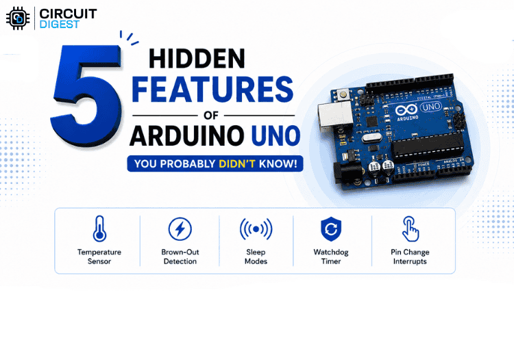
The Arduino UNO R3 is often the first board people use to learn electronics and programming. Connect an LED, read a sensor, control a motor, upload a sketch, and it can seem like you’ve already discovered everything the board can do.
But there is much more going on underneath.
At the heart of the UNO R3 is the ATmega328P microcontroller. That small chip contains hardware features that many Arduino users never directly use, including an internal temperature sensor, brown-out detection, multiple sleep modes, a watchdog timer, and pin-change interrupts. These are capabilities of the microcontroller that the UNO R3 is built around.
Here are five of the most interesting ones you can actually explore on an Arduino UNO R3.
1. Your Arduino Can Measure Its Own Temperature
When you want to measure temperature with an Arduino, you would normally connect an external sensor such as an LM35, TMP36, DHT11, or DS18B20.
But the ATmega328P already has a temperature-sensing circuit inside the microcontroller.
The sensor is internally connected to the ADC, allowing the chip to obtain a temperature-related reading without using an external temperature sensor. The ATmega328P datasheet specifically lists temperature measurement among its peripheral features.
The basic path is:
Internal temperature sensor → ADC → digital reading → Serial Monitor
How to Demonstrate It
Connect your UNO R3 to your computer and configure the ATmega328P's ADC to read its internal temperature channel.
Then print the ADC result to the Serial Monitor.
For a visually interesting demonstration, start with the reading on screen and gently warm the microcontroller. You should see the reading change.
You don't need:
- An LM35
- A DHT11
- A TMP36
Any other external temperature sensor
The sensing circuit is already inside the microcontroller.
One Important Catch
This is not a precision thermometer. The internal sensor has significant variation between individual chips, so the reading should be treated as approximate rather than as an accurate measurement of room temperature. So the safest way to describe it is:
“Your Arduino has a temperature sensor inside its main chip.”
Rather than:
“Your Arduino can accurately measure room temperature.”
Video Reference
How to Read the Internal Temperature Sensor in Arduino - Electro Hijibiji
https://www.youtube.com/watch?v=43l6Ibk7Spw
2. Your Arduino Can Detect When Its Supply Voltage Gets Too Low
Another capability that doesn't require an external sensor is Brown-Out Detection, or BOD.
The ATmega328P can monitor its supply voltage. When brown-out detection is enabled and the voltage falls below the selected threshold, the microcontroller can be held in reset rather than continuing to operate under an insufficient supply voltage. The chip also provides a brown-out reset flag that allows software to determine that a brown-out reset occurred.
Think of it as a built-in low-voltage protection mechanism for the microcontroller:
Normal supply
↓
Supply voltage falls
↓
Brown-out threshold
↓
MCU reset/held in reset
This can be particularly useful in battery-powered embedded systems, where the supply voltage can change as the battery discharges.
How to Demonstrate It
For a controlled demonstration, use an appropriate adjustable power supply and a multimeter.
Gradually reduce the microcontroller's supply voltage while monitoring the system.
A simple visual sequence would be:
5 V → voltage decreases → threshold → reset
Safety
Don't experiment by randomly lowering the UNO's 5V rail while the board is simultaneously being powered through USB. Use a controlled setup and understand the board's power path before experimenting.
Video Reference
Arduino Project to Product – Part 4: Optimising Operating Voltage - Shawn Hymel / DigiKey
https://www.youtube.com/watch?v=7a4XYppZ6Bc
This is a useful engineering reference for ATmega328P operating voltage and brown-out detection.
3. Your Arduino Can Literally Go to Sleep
The ATmega328P doesn't have to keep its CPU fully active all the time.
It has six hardware sleep modes:
- Idle
- ADC Noise Reduction
- Power-save
- Power-down
- Standby
- Extended Standby
Each mode disables different parts of the chip to reduce power consumption.
The most interesting mode for low-power applications is Power-down.
Instead of keeping the microcontroller awake while it has nothing to do, you can design a system like this:
Do some work → sleep → wake → do some work → sleep again
This is extremely useful for battery-powered devices.
Imagine a sensor that only needs to collect data once every minute. There is little reason to keep the CPU fully active for the entire minute.
How to Demonstrate It
Use an Arduino UNO R3 with an LED and a wake-up source such as a push button.
Show:
Arduino running
↓
Arduino enters sleep
↓
Activity stops / current drops
↓
Wake-up event
↓
Arduino continues
For an even better demonstration, measure the current and show the difference between active and sleep states.
Why is this Useful?
Sleep modes are useful for:
- Battery-powered sensors
- Remote data loggers
- Portable electronics
- Environmental monitors
- Low-power embedded systems
The basic idea is simple:
Don't spend power doing nothing.
Video Reference
Arduino Project to Product - Part 8: How to Put Arduino to Sleep - Shawn Hymel / DigiKey
https://www.youtube.com/watch?v=eQZf5pbEVxE
This is particularly useful because it demonstrates the relationship between sleep mode and power consumption.
4. Your Arduino Can Restart Itself When Software Gets Stuck
This is one of the most useful features for real-world embedded projects.
The ATmega328P includes a hardware Watchdog Timer with a separate on-chip oscillator. The watchdog can be configured with a timeout, and if the software fails to service it before that timeout expires, it can trigger a system reset.
Imagine an unattended robot.
Everything is working:
Sensors → code → motors → communication
Then a software bug sends the program into an infinite loop.
Without a recovery mechanism, the system can remain frozen.
With the watchdog:
Program running
↓
Software gets stuck
↓
Watchdog isn't serviced
↓
Timeout
↓
Hardware reset
↓
Program starts again
The watchdog doesn't actually understand that the program “crashed.” It simply detects that it wasn't serviced in time.
How to Demonstrate It
You can deliberately create an infinite loop after enabling the watchdog:
#include <avr/wdt.h>
void setup() {
Serial.begin(9600);
Serial.println("Arduino STARTED");
wdt_enable(WDTO_2S);
}
void loop() {
Serial.println("Running...");
delay(500);
// Simulate a software freeze
while (true) {
}
}
The Serial Monitor will initially show:
Arduino STARTED
Running...
Running...
Running...
Then the program stops responding.
After the watchdog timeout, the ATmega328P resets and setup() runs again.
You should see:
Arduino STARTED
again.
That makes a great demonstration because it looks like the Arduino has recovered itself.
Where is this Useful?
Watchdog timers are especially useful in:
- Robotics
- IoT devices
- Remote sensors
- Industrial controllers
- Security systems
- Unattended embedded systems
If something is supposed to keep running for hours, days, or months without someone nearby to press RESET, a watchdog can provide an important recovery mechanism.
Video Reference
Tutorial: Using the Arduino Watchdog Timer - MAKE Course
https://www.youtube.com/watch?v=BDsu8YhYn8g
The video specifically covers the watchdog timer on the ATmega328P and its automatic timeout/reset behavior.
5. Your Arduino Can Wake Up When a Configured Pin Changes
This is where the sleep feature becomes even more interesting.
The ATmega328P provides Pin Change Interrupts, commonly called PCINT.
On the UNO R3, pin-change interrupt sources are spread across groups of GPIO pins. For example, the ATmega328P uses PCINT groups corresponding to:
D8 - D13
A0 - A5
D0 - D7
Electronoobs' detailed ATmega328P tutorial explains these groups, the corresponding interrupt vectors, and how to configure them.
But the really useful part is this:
Pin-change interrupts can be used to wake the ATmega328P from Power-down sleep.
So you can create this sequence:
Arduino running
↓
MCU enters sleep
↓
Button changes a configured pin
↓
Pin-change interrupt
↓
Arduino wakes
The microcontroller doesn't have to keep executing a loop asking:
“Is the button pressed?”
while it is sleeping.
The hardware can detect the configured change and use the interrupt as a wake-up event.
How to Demonstrate It
For example, connect a push button like this:
A0 ───── BUTTON ───── GND
Configure A0 with the internal pull-up resistor and enable the appropriate pin-change interrupt.
Then show:
Arduino awake
↓
Arduino enters sleep
↓
Current/activity drops
↓
Press button
↓
A0 changes state
↓
Pin-change interrupt
↓
Arduino wakes
Why is this Different from Normal Button Reading?
Normally, your program might repeatedly poll the pin:
Is the button pressed?
Is the button pressed?
Is the button pressed?
That means the CPU has to remain active.
With the sleep + interrupt approach, the CPU can sleep until the hardware detects the configured event.
Video Reference
Pin Change Interruptions ISR | PCINT | Arduino101- Electronoobs
https://www.youtube.com/watch?v=ZDtRWmBMCmw
This video demonstrates pin-change interrupts on the Arduino/ATmega328P and explains the PCINT groups and configuration.

Add a comment
No account needed. Your comment appears once a moderator has reviewed it.