




Measuring distance with a conventional tape measure is simple, but it becomes less convenient when the measurement also needs to be calculated, recorded, or taken from an awkward angle. A digital measuring tape can eliminate much of this manual work by combining distance sensing with calculation and a compact user interface.
SmartTape is a pocket-sized, battery-powered digital laser measuring tool designed around this idea. As a smart digital measuring tape, it can measure distance, calculate area and volume, determine indirect height using tilt information, track maximum and minimum distances, and work as a digital spirit level. All of these functions are controlled using a single spring-return rotary knob and displayed on a 1.3-inch OLED.
At the heart of SmartTape is the STM32G491CEU6, a 170 MHz ARM Cortex-M4F microcontroller. The MCU handles the ranging sensor, precision inclinometer, OLED display, rotary input, battery monitoring, laser control, non-volatile settings, and the application state machine.
For distance measurement, we used the ST VL53L4CX Time-of-Flight sensor, which provides ranging capability up to 6 metres in LONG mode, making this digital tape measure with laser targeting suitable for most indoor and workshop measurements. The device also incorporates a Murata SCL3300-D01-10 three-axis inclinometer, allowing the firmware to use both distance and angle information for indirect height measurement.
Rather than assembling the project from development boards and breakout modules, the complete system was designed around a custom PCB. The optical components are placed on a separate small daughterboard, while the main PCB contains the STM32, power circuitry, display interface, input controls, and debugging interface.
The firmware is also built from the ground up in embedded C. The user interface, filtering algorithms, measurement calculations, Flash settings storage, and OLED graphics engine are all implemented specifically for the hardware.
The result is a compact digital laser tape measure that combines laser ranging, precision inertial sensing, custom graphics, and embedded signal processing in a single handheld device.
Code File


PCB Gerber File

| Value | Manufacturer | DigiKey Part Number | Datasheet Link | Quantity |
|---|---|---|---|---|
| 10uF 0603 | Samsung Electro-Mechanics | 1276-1038-1-ND | 
|
5 |
| 1uF 0603 | Samsung Electro-Mechanics | 1276-1946-1-ND |
|
6 |
| 0.1uF 0603 | Murata Electronics | 490-3285-1-ND |
|
14 |
| 8pF 0603 | YAGEO | 311-1057-1-ND |
|
2 |
| 0R 0603 | Bourns Inc. | CR0603AJ/-000EASCT-ND |
|
1 |
| 1K 0603 | YAGEO | 311-1.00KHRCT-ND |
|
3 |
| 1.65K 0603 | YAGEO | 13-AC0603FR-071K65LCT-ND |
|
1 |
| 3.74K 0603 | YAGEO | YAG2652CT-ND |
|
1 |
| 5.1K 0603 | YAGEO | 13-AC0603FR-135K1LCT-ND |
|
2 |
| 10K 0603 | YAGEO | 311-10.0KMCT-ND |
|
8 |
| 56K 0603 | YAGEO | 13-RC0603FR-1356KLCT-ND |
|
1 |
| 100K 0603 | YAGEO | 311-100KHRCT-ND |
|
3 |
| AO3401A | UMW | 4518-AO3401ACT-ND |
|
1 |
| USB4105-GF-A-060 | Global Connector Technology (GCT) | 2073-USB4105-GF-A-060CT-ND |
|
1 |
| B2B-PH-K-S(LF)(SN) | JST Sales America Inc. | 455-1704-ND |
|
1 |
| STM32G491CEU6 | STMicroelectronics | 497-STM32G491CEU6-ND |
|
1 |
| VL53L4CXV0DH/1 | STMicroelectronics | 497-VL53L4CXV0DH/1CT-ND |
|
1 |
| SCL3300-D01-10 | Murata Electronics | 490-18218-1-ND |
|
1 |
| LD39200PU33R | STMicroelectronics | 497-15229-1-ND |
|
1 |
| LTC4057ES5-4.2#TRMPBF | Analog Devices Inc. | 505-LTC4057ES5-4.2#TRMPBFCT-ND |
|
1 |
| CAT4002ATD-GT3 | onsemi | CAT4002ATD-GT3OSTR-ND |
|
1 |
| RLD65NZN5 | ROHM Semiconductor | 846-RLD65NZN5-00A-ND |
|
1 |
| ECS-240-8-37B-CKY-TR | ECS Inc. | XC3063CT-ND |
|
1 |
| PEC11R-4215F-S0024 | Bourns Inc. | PEC11R-4215F-S0024-ND |
|
1 |
How the Digital Measuring Tape Works
SmartTape is built around two primary measurement systems: a Time-of-Flight ranging sensor for distance and a precision inclinometer for angular measurements.
The VL53L4CX emits infrared light and determines distance from the time taken for the reflected signal to return to the sensor. The visible red laser diode is separate from the ranging system and acts as a targeting pointer, allowing the user to see where the measurement is being taken.
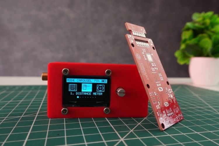
The STM32 continuously acquires ranging data and evaluates the quality of each measurement. Because raw ToF measurements can contain occasional outliers and become less stable at longer distances, the firmware applies a two-stage filtering system consisting of a moving median followed by a distance-adaptive exponential moving average.
The SCL3300 provides the angular information required by the HEIGHT and LEVEL modes. In HEIGHT mode, the device measures the slant distance to the target and combines it with the measured pitch angle to calculate the vertical component of that distance.
The rotary knob acts as the primary user interface. Unlike a conventional continuous rotary encoder, the spring-return mechanism produces a single navigation action for each clockwise or counterclockwise flick and then returns to its centre position. The integrated push switch provides selection and additional gestures.
The OLED is driven through I2C and uses a custom framebuffer-based graphics engine. Instead of relying on a conventional character-based display interface, SmartTape renders its measurement values, icons, level indicators, and animated menu directly into a 128 × 64 pixel framebuffer.
Measurement Modes of This Smart Digital Measuring Tape
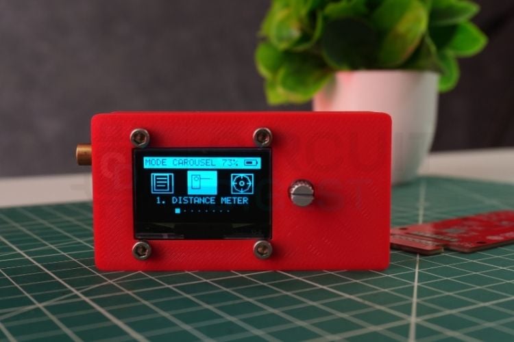
The firmware organizes the main functions into an eight-mode carousel. The user can move through the modes by flicking the rotary knob and pressing the knob to select the required function.
| Mode | Function | Description |
| DIST | Distance Meter | Continuous laser distance measurement with pitch and roll alignment indicators |
| LEVEL | Spirit Level | Full-screen digital bubble level with pitch, roll, and inclinometer temperature |
| HEIGHT | Indirect Height | Calculates vertical height from slant distance and inclination |
| AREA | Area Calculator | Takes length and width measurements and calculates area |
| VOLUME | Volume Calculator | Takes length, width, and height measurements and calculates volume |
| CYLINDER | Tank/Pipe Volume | Calculates cylindrical volume from diameter and height |
| MAXMIN | Boundary Tracker | Continuously tracks maximum and minimum measured distance |
| MEMORY | Measurement Log | Provides access to the last ten saved measurements |
Measurements can be displayed in CM, MM, M, or inches. The selected unit is stored in the STM32's internal Flash memory so that it remains available after the device is powered off.
Components Used in This Digital Measuring Tape
The SmartTape hardware is built almost entirely from individual components mounted directly on the custom PCB rather than using development-board modules.
| Component | Part Number | Qty | Function |
| Microcontroller | STM32G491CEU6, QFN-48 | 1 | Main processor and application controller |
| ToF Sensor | ST VL53L4CX, LGA-12 | 1 | Laser Time-of-Flight distance measurement |
| Inclinometer | Murata SCL3300-D01-10 | 1 | Precision three-axis inclination measurement |
| OLED | SH1106 1.3-inch 128 × 64 | 1 | Main graphical display |
| Laser Diode | ROHM RLD65NZN5, 650 nm | 1 | Visible measurement targeting laser |
| Laser Driver | ON Semiconductor CAT4002A | 1 | Constant-current laser driver |
| 3.3 V LDO | ST LD39200PU33R | 1 | Main 3.3 V power regulator |
| Battery Charger | LTC4057ES5-4.2 | 1 | Li-Ion/LiPo battery charging |
| P-MOSFET | AO3401A | 1 | Hardware battery power switching |
| Rotary Encoder | Hongyan RS11 / Bourns PEC11R | 1 | Navigation and user input |
| USB Type-C | 16-pin mid-mount connector | 1 | USB power and charging input |
| Crystal | ECS-240-8-37B-CKY-TR, 24 MHz | 1 | MCU clock reference |
| Slide Switch | EG1215AA SPDT | 1 | Hardware power control |
| Schottky Diode | SOD-323 | 1 | USB input reverse-current protection |
| TVS Diodes | 0402 bidirectional TVS | 2 | USB ESD protection |
| Battery Connector | B2B-PH-K-S | 1 | Li-Ion/LiPo battery connection |
| SWD Header | 2 × 3, 2.54 mm | 1 | Programming and debugging |
The remaining passive components provide power decoupling, pull-ups, battery voltage sensing, laser current programming, USB-C termination, and input debounce.
Schematic Design and Circuit Overview
The SmartTape schematic was designed in Altium Designer and divided into five logical areas: power, sensing, display, input, and debug. Separating these functions makes the design easier to understand and also helps keep sensitive measurement circuitry away from noisy power and digital signals.
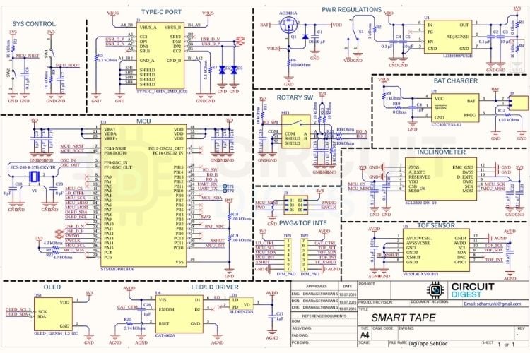
The power section handles USB-C input, battery charging, hardware power switching, and 3.3 V regulation. The sensing section contains the VL53L4CX and SCL3300, while the display and input sections connect the OLED and rotary control to the STM32.
Power Management: USB-C, Battery Charging, and 3.3 V Regulation
The power path begins at the USB Type-C connector. SmartTape is configured as a USB power sink using 5.1 kΩ resistors on CC1 and CC2. This lets the device draw power from a standard USB-C charger without a USB Power Delivery controller.
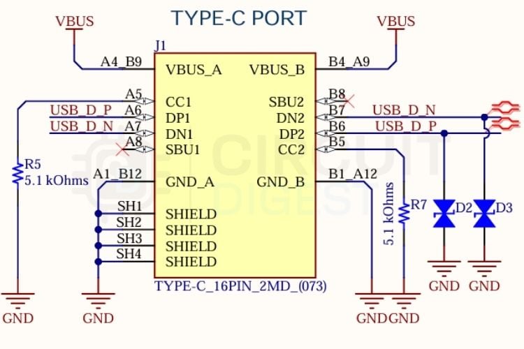
VBUS then passes through a Schottky diode before reaching the battery-charging circuit. The diode provides reverse-current protection when the device is being powered from the battery while a USB cable is connected.
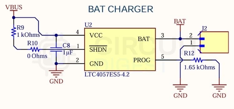
The LTC4057ES5-4.2 handles battery charging. Its PROG pin uses a 1.65 kΩ resistor to set the charging current:
I_CHG = (1000 × 1.0 V) / 1650 Ω
which gives approximately:
I_CHG ≈ 0.606 A
The charger handles the constant-current/constant-voltage charging process without requiring firmware control.
The main power switch is implemented using an AO3401A P-channel MOSFET. The physical slide switch controls the MOSFET gate rather than carrying the complete system load directly. A 100 kΩ pull-up keeps the MOSFET turned off when the switch is open, while closing the switch pulls the gate toward ground and powers the system.
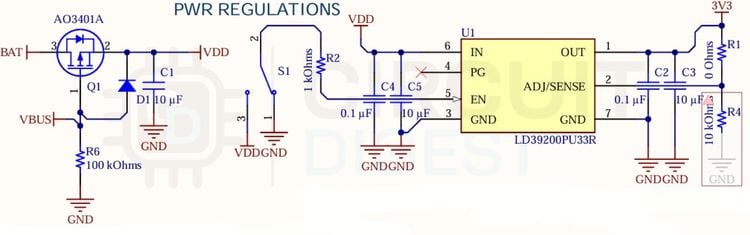
The battery voltage is then regulated to 3.3 V by the LD39200PU33R. The regulator is capable of supplying up to 2 A and has a low dropout voltage, which allows the circuit to continue operating as the Li-Ion battery voltage falls.
Several bulk and bypass capacitors are placed around the regulator and main supply rails. The output includes three 10 µF capacitors and two 1 µF capacitors to provide additional transient energy storage for the system.
Distance Measurement With the VL53L4CX
The primary distance sensor is the ST VL53L4CX, a compact Time-of-Flight sensor containing the optical ranging circuitry required for laser distance measurement.
Instead of mounting the sensor directly on the main PCB, we placed the VL53L4CX on a separate optical daughterboard. The daughterboard connects to the main PCB through seven castellated connections.
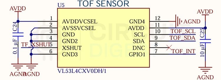
This arrangement allows the optical components to be positioned independently of the main electronics and enclosure. It also keeps the VCSEL and SPAD sensing area physically separated from many of the digital signals on the main board.
The VL53L4CX communicates with the STM32 through I2C1 at 400 kHz. Its I2C address is 0x29.
Two GPIO signals are also connected to the sensor. The XSHUT signal provides hardware shutdown control, while the INT signal indicates when a new ranging result is available.
For the long-distance measurement configuration, the firmware uses LONG distance mode with a 200 ms timing budget. Cover-glass crosstalk compensation is also enabled to account for reflections from the protective optical window.
Precision Inclination Measurement with the SCL3300
Distance alone is not enough for some measurements. For example, measuring the height of a point on a wall from the floor requires the device to know both the distance to the target and the angle at which the measurement was taken.
SmartTape uses the Murata SCL3300-D01-10 precision inclinometer for this purpose.
The SCL3300 communicates with the STM32 through SPI1 using approximately a 5.3 MHz clock speed. The interface uses fixed 32-bit SPI frames with CRC-8 integrity checking.
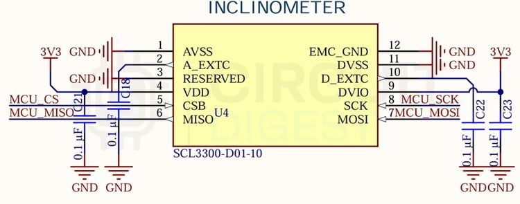
The device provides three-axis inclination information with an angular resolution of approximately 0.0055°. This makes it suitable for the LEVEL function as well as the trigonometric calculations used by HEIGHT mode.
The inclinometer also provides temperature information, which is displayed in the LEVEL interface.
Visible Laser and Constant-Current Driver
The VL53L4CX provides the actual distance measurement, while SmartTape uses a separate visible red laser to give the user a clear targeting point, the defining feature of any digital tape measure with laser guidance.
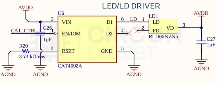
The laser is based on the ROHM RLD65NZN5 650 nm red laser diode. It is driven through the CAT4002A constant-current LED/laser driver rather than being connected directly to a GPIO.
The laser current is programmed using a 3.74 kΩ resistor:
I_LASER = (1.2 V / 3740 Ω) × 100
giving approximately:
I_LASER ≈ 32 mA
The CAT4002A EN/DIM input is connected to the STM32 so that the firmware can enable or disable the laser as required. The laser diode is mounted on the optical daughterboard alongside the ranging sensor, with a collimating lens aperture aligned with the enclosure opening.
OLED Display Interface
SmartTape uses a 1.3-inch 128 × 64 SH1106 monochrome OLED as its primary display.
The OLED is connected to I2C2 at 400 kHz and uses address 0x3C. The display interface is not treated simply as a text display. Instead, the firmware maintains a complete off-screen framebuffer.
The SH1106 contains 132 columns of display RAM, which provides useful additional memory compared with a conventional 128-column SSD1306 implementation. SmartTape uses this architecture to maintain a 128 × 64 framebuffer and transfer complete frames to the display.
This approach is particularly useful for the animated interface because the firmware can construct the entire screen before updating the OLED, rather than modifying individual display elements during rendering.
Rotary Encoder User Interface
The entire SmartTape interface is operated through a single spring-return rotary control.
The selected encoder is based on the Hongyan RS11 / Bourns PEC11R-style spring-return mechanism. Instead of continuously rotating like a conventional rotary encoder, the knob can be flicked clockwise or counterclockwise and then returns to its centre position.
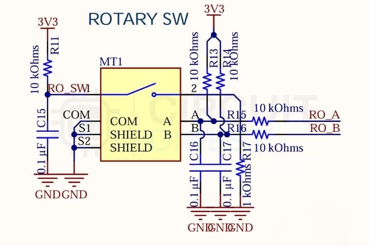
The two encoder phases are connected to GPIO inputs with 10 kΩ pull-up resistors. Each signal also includes an RC debounce network using a 0.1 µF capacitor.
The integrated push button provides the selection function as well as the additional press, long-press, double-press, and press-and-twist gestures used by the firmware.
This lets a single physical control handle mode navigation, measurement capture, settings, and screen transitions without adding multiple buttons to the compact enclosure.
Battery Voltage Monitoring
SmartTape also monitors its battery voltage using one of the STM32 ADC inputs. A 100 kΩ / 100 kΩ resistor divider reduces the battery voltage to half its original value before feeding it into ADC3 Channel 1 on PB1.
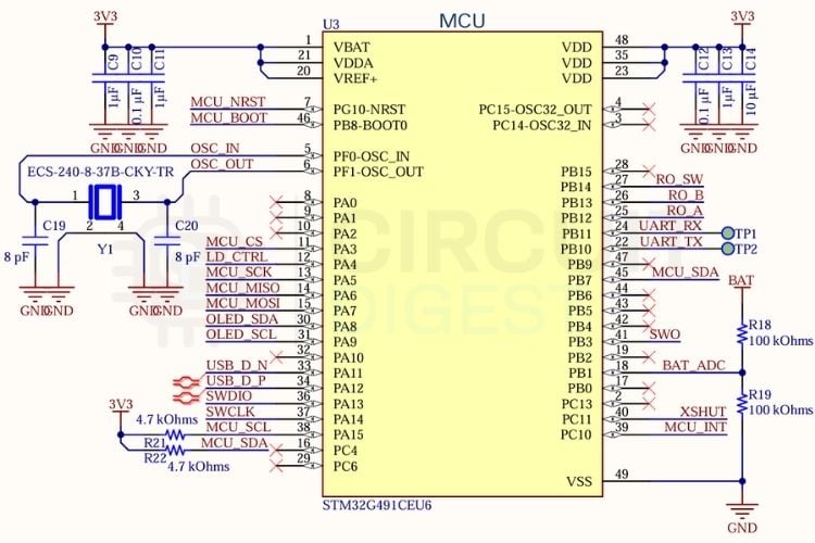
The firmware reconstructs the battery voltage using:
V_BAT = 2 × (ADC_RAW / 4095) × 3.30 V
The resulting voltage is filtered before being used to update the battery indication shown by the user interface.
SWD Programming and Debug Interface
A six-pin SWD header is provided on the PCB for programming and debugging the STM32.
The header exposes SWDIO, SWCLK, NRST, SWO, 3.3 V, and GND, allowing an ST-Link programmer to be connected directly to the board.
USART3 TX and RX test pads are also provided for UART logging during development. This gives access to both low-level debugging and runtime telemetry without requiring additional connectors on the finished enclosure.
PCB Design
The SmartTape PCB was designed as a compact two-layer Altium Designer board. Since the device combines optical sensing, precision inertial measurement, USB, battery power, and a high-speed microcontroller in a small enclosure, component placement was an important part of the design.
The STM32G491CEU6 uses a QFN-48 package with an exposed ground/thermal paddle. The paddle is connected to a solid copper region on the lower layer, providing a low-impedance ground path and a thermal path away from the device.
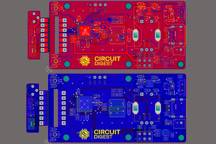
The 24 MHz crystal and its 8 pF load capacitors are positioned immediately next to the STM32 PF0/PF1 oscillator pins. Keeping these connections short minimizes unwanted parasitic effects in the oscillator loop.
Decoupling capacitors are positioned close to the respective IC power pins. The design uses 0.1 µF ceramic capacitors near the individual supply connections, along with larger 10 µF capacitors around the main supply rails.
The USB D+ and D− signals are routed as a length-matched differential pair. TVS protection is placed between the USB connector and the STM32 USB interface to protect against ESD during cable insertion and removal.
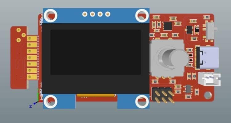
The optical daughterboard is connected through seven castellated pads. This gives the laser and ToF sensor the mechanical freedom required to align with the enclosure's optical opening.
The battery-voltage ADC trace is also kept physically away from the SPI and I2C signal paths to reduce the possibility of digital switching noise coupling into the analog measurement.
The project repository includes the generated Gerber files required for PCB fabrication.
PCB Assembly
Most of SmartTape's components are surface-mounted, with the battery connector and SWD header as the primary through-hole components.
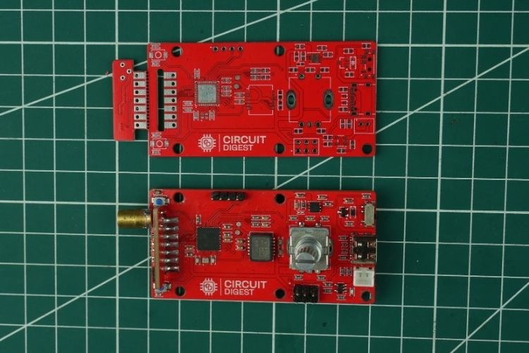
Assembly begins with the smaller passive components before moving to the SOT-23 devices and more difficult packages. The crystal, encoder, OLED, and connectors are installed later so that they do not interfere with the earlier soldering operations.
The DFN-6 LD39200 LDO requires particular attention because its exposed bottom pad must make proper thermal and electrical contact with the PCB.
The STM32G491 QFN-48 is assembled using solder paste and careful alignment, followed by inspection of the perimeter pins and exposed ground paddle.
The SCL3300 also requires careful placement because it is part of the precision sensing system. After the SMD assembly is complete, the rotary encoder, OLED, battery connector, and SWD header can be installed.
Before applying power, the completed board should be inspected under magnification and checked for shorts between VBAT, VDD, VBUS, and ground. The SWD interface can then be tested with an ST-Link before the battery is connected.
3D-Printed Enclosure
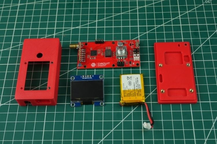
The electronics are housed inside a custom two-piece clamshell enclosure. The design consists of separate top and bottom sections that retain the PCB, battery, display, encoder, and optical components.
Three STEP models are provided for the enclosure design, including two top revisions and one bottom section.
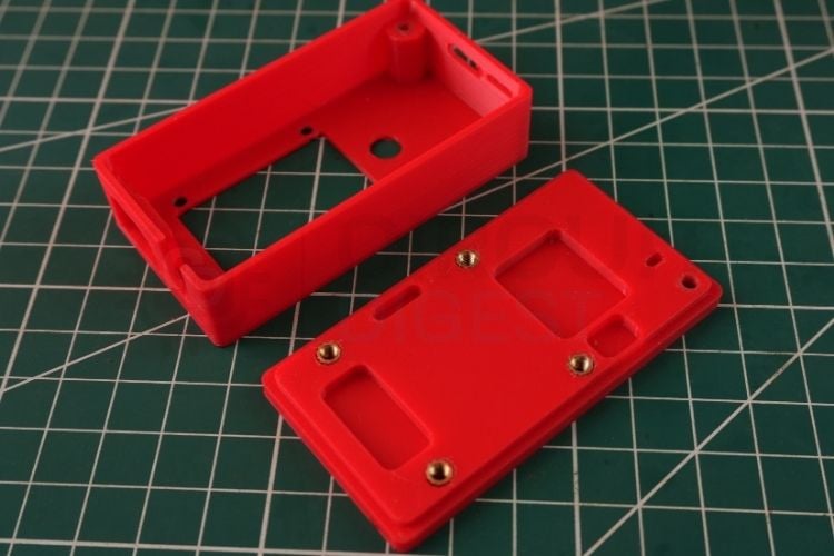
The top enclosure includes a dedicated opening for the OLED and a recessed area around the rotary encoder. The optical daughterboard is positioned so that the visible laser aligns with a small circular aperture in the front of the housing. The STL file is available on GitHub for reference
The bottom section contains the battery compartment and PCB retention features. The USB-C opening allows the battery to be charged without removing the enclosure. The supplied design is intended to be printed using PLA or PETG with a 0.2 mm layer height and approximately 20% infill.
Firmware Architecture
The SmartTape firmware is written in embedded C and developed using STM32CubeIDE, the STM32G4 HAL, and ST's VL53L4CX Ultra-Lite Driver.
The firmware runs without an RTOS. Instead, the application is organized around a main loop that executes approximately every 30 ms. This provides a simple execution model while still giving the interface enough update frequency for responsive controls and animation.
The firmware can broadly be divided into hardware initialization, sensor acquisition, signal processing, application state management, graphics rendering, power management, and telemetry.
Boot Sequence
When SmartTape is powered on, the firmware follows a fixed initialization sequence. The HAL is initialized first, followed by the 170 MHz system clock configuration using the 24 MHz external crystal and PLL.
Once the system clock is configured, the required peripherals are initialized. ADC3 is configured for battery monitoring, while I2C1 is used for communication with the VL53L4CX distance sensor and I2C2 is used for the OLED display.
SPI1 is initialized for communication with the SCL3300, while USART3 is configured for development telemetry. USB CDC is also initialized to provide USB-based communication with the host system.
Before battery measurements begin, the ADC is calibrated to ensure that the voltage readings are accurate and consistent.
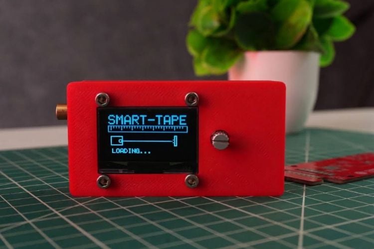
The VL53L4CX receives a hardware reset through its XSHUT line before being initialized for long-range operation. The OLED then displays the SmartTape startup animation, followed by initialization and WHOAMI verification of the SCL3300.
Finally, the stored user settings are loaded from Flash. If valid settings are not present, the firmware falls back to its default configuration.
The Main Loop
The main application loop executes approximately once every 30 ms, or roughly 33 times per second.
Each iteration begins by checking the rotary encoder and its push button. The firmware distinguishes between normal rotation, short presses, long presses, double presses, and combined press-and-twist gestures.
The ToF sensor is checked without blocking the rest of the application. When a new measurement becomes available, the firmware evaluates the measurement and passes it through the distance filtering pipeline.
A 32-bit SPI transaction retrieves the latest SCL3300 information. The application state machine then determines which interface should be rendered based on the current menu, measurement mode, or settings screen.
The firmware also checks the inactivity timer, updates the OLED framebuffer, and outputs USB CDC telemetry for development and testing.
This state-machine architecture keeps the different measurement modes independent while allowing all of them to share the same sensor and display infrastructure.
Distance Filtering: Moving Median and Adaptive EMA
One of the more important firmware sections is the processing applied to the raw ToF measurements.
A raw laser ranging signal can occasionally contain outliers. At longer distances, the measurement can also become more susceptible to variation. A fixed smoothing value would therefore create a compromise: aggressive smoothing would make short-distance measurements feel slow, while weak smoothing would allow too much variation at longer distances. SmartTape addresses this with a two-stage filter.
Moving Median Filter
The first stage maintains the latest seven measurements in a ring buffer.
When a new sample arrives, the seven values are sorted and the median value is selected. Because the median is resistant to isolated outliers, a single abnormal ToF measurement cannot immediately move the filtered output significantly.
Distance-Adaptive EMA
The median result then passes into an exponential moving average whose smoothing factor changes according to the measured distance.
The firmware calculates:
α = 1 / (1 + 0.0008 × distance_mm)
The resulting value is limited to a range of 0.08 to 0.60.
At approximately 500 mm, the filter uses an alpha of around 0.60, keeping the response relatively fast. At around 4000 mm, alpha falls to approximately 0.23, providing stronger smoothing for more stable long-range readings.
This adaptive approach avoids using one fixed filter response for the entire measurement range.
Indirect Height Measurement
The HEIGHT mode combines the two sensing systems of SmartTape. Instead of pointing the laser directly at the top of an object and physically aligning the device vertically, the user can measure the slanted distance to the target while the inclinometer determines the angle.
If the measured slant distance is (D) and the pitch angle is θ, the vertical component is calculated as:
raw_h = D × sin(θ)
The physical mounting position of the sensor also has to be considered. The sensor is mounted approximately 2.4 cm above the floor reference surface, so the firmware applies an offset correction:
uncal_h = raw_h − 2.4 cm × cos(θ)
A final two-point empirical calibration is then applied using the gain and bias determined during development:
height = (uncal_h × 1.0989) + 2.242 cm
The resulting value is used as the indirect floor-to-target height measurement displayed by HEIGHT mode.
Storing Settings in Internal Flash
SmartTape allows the user to change settings such as the display unit, measurement datum, and rear reference offset.
These settings are stored in the last 2 KB Flash page of the STM32G4. The firmware uses Page 255 at address 0x0807F800.
A magic value is stored along with the configuration so that the firmware can determine whether the Flash contents contain a valid configuration.
When the user explicitly confirms a settings change, the firmware unlocks the Flash, erases the configuration page, writes the configuration data, and locks the Flash again.
The stored information includes the magic value, unit mode, datum mode, rear offset, and a check byte.
Settings are therefore only written when the user confirms the change rather than continuously during operation. This reduces unnecessary Flash erase/write cycles and preserves the expected Flash endurance of approximately 10,000 cycles.
Battery Measurement and Filtering
Battery voltage is sampled independently from the main ranging loop.
Every 500 ms, the firmware collects 32 ADC samples from the battery-divider input. Instead of using a simple arithmetic average, the samples are sorted, and the highest and lowest quartiles are discarded.
The remaining 16 samples are averaged to form a trimmed mean. This helps reject abnormal ADC readings that can occur due to switching activity and laser-driver current pulses.
The trimmed result is then passed through a slow IIR low-pass filter using an alpha value of 0.08. A 1% hysteresis is also applied to the battery percentage display to prevent the indicator from repeatedly changing between adjacent values.
Custom OLED Graphics Engine
The OLED interface is implemented using a custom graphics engine rather than relying on a simple text rendering library.
A 1024-byte framebuffer represents the complete 128 × 64 display. Drawing functions for lines, rectangles, circles, and icons modify this framebuffer before the complete image is transferred to the SH1106.
The display update therefore consists of rendering the new interface into memory and then sending the framebuffer to the OLED in page-sized transfers.
One of the distinctive parts of the interface is the custom parametric seven-segment font renderer. Instead of storing fixed bitmap characters for every font size, the firmware constructs the characters from vector-like segments.
The renderer receives the character, desired dimensions, and stroke thickness and generates the required segment geometry. This allows the same font system to be used for large measurement values as well as compact secondary information.
For example, DIST mode uses a large 15 × 30 pixel-style character format, while other measurement modes use a smaller 13 × 22 format. The LEVEL interface uses an even smaller format for its sidebar telemetry.
Animated Menu Interface
The mode selection screen is implemented as an animated carousel.
When the encoder is flicked, the firmware changes an animation offset variable called anim_x. The selected card moves horizontally and then settles into position over several frames.
The animation starts with a 36-pixel displacement and reduces the offset by 9 pixels every 30 ms frame. This results in a four-frame, approximately 120 ms transition.
Because the OLED framebuffer is rendered before the complete screen update, the interface can perform these transitions without relying on a separate graphics processor.
Using SmartTape
Starting the Device
Move the hardware power switch to the ON position. The OLED first displays the SmartTape startup animation, including a white sweep followed by the SmartTape title and an animated laser-beam graphic. After initialization, the device enters the mode carousel.
Selecting a Mode
Flick the rotary knob clockwise to move forward through the available functions or counterclockwise to move backwards. Pressing the knob selects the highlighted mode.
Distance Measurement
In DIST mode, the visible red laser is activated, and the device continuously displays the measured distance.
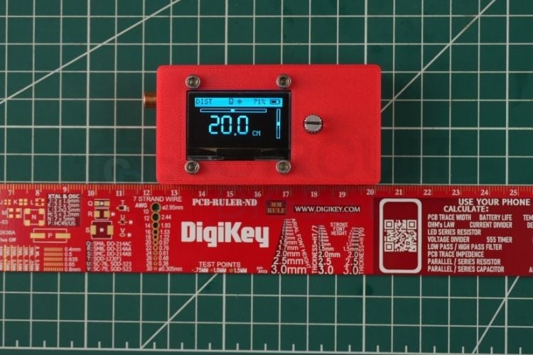
The interface also includes horizontal and vertical level indicators based on the inclinometer data, helping the user align the instrument while taking a measurement.
Pressing the knob freezes the displayed measurement and disables the laser. Pressing again returns the device to continuous ranging.
Area Measurement
AREA mode requires two measurements. The first measurement is used as the length. The user then changes the orientation of the device and takes the second measurement for the width.
SmartTape calculates the resulting area from the two captured dimensions and displays the result.
Volume Measurement
VOLUME mode extends the same approach to three dimensions. The user captures length, width, and height sequentially. The firmware then calculates:
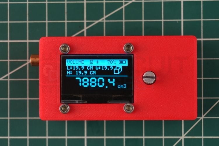
Volume = L × W × H
and displays the resulting volume using the selected unit system.
Cylinder Measurement
CYLINDER mode is intended for cylindrical objects such as tanks and pipes. The first measurement captures the diameter and the second captures the height.
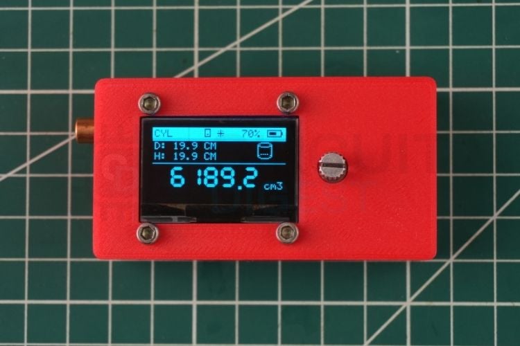
The firmware then calculates the cylindrical volume using:
Volume = π × R² × H
Spirit Level
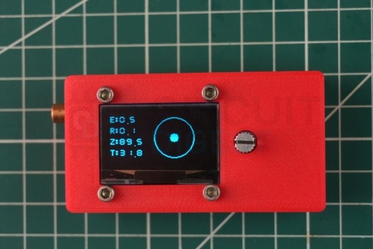
LEVEL mode uses the SCL3300 to turn the OLED into a digital two-dimensional bubble level. The display provides a graphical representation of the current tilt together with numerical pitch and roll information. The inclinometer temperature is also displayed.
Settings
The settings interface can be opened by performing a long press on the rotary knob. The interface provides three configurable parameters: UNIT, DATUM, and OFFSET.
The UNIT parameter allows the user to select the preferred measurement unit from CM, MM, M, or INCH. The DATUM parameter determines the measurement reference point and can be set to either REAR or FRONT.
The OFFSET parameter is used to adjust the rear reference position when required. The selected parameter can be edited using the rotary control and confirmed by pressing the knob.
Once a setting is confirmed, it is stored in the internal Flash memory so that the selected configuration is retained after the device is powered off and restarted.
Auto-Sleep
SmartTape is designed to conserve battery power when it is not being used. After approximately three minutes of inactivity, the firmware turns off the laser and OLED and places the VL53L4CX into hardware shutdown using XSHUT.
The device can wake when the inclinometer detects movement or when the rotary control is operated.
Conclusion
SmartTape demonstrates how a compact handheld digital measuring tape can combine several measurement functions around a carefully designed embedded system.
The project brings together the VL53L4CX Time-of-Flight sensor, SCL3300 precision inclinometer, STM32G491CEU6 microcontroller, visible laser targeting system, custom OLED graphics engine, and battery-management circuitry on a purpose-built PCB.
The interesting part of the design is not only the individual components but the way they are combined in firmware. Distance measurements are processed using a moving-median and distance-adaptive EMA filter, indirect height is calculated using both ranging and inclination data, battery measurements use trimmed averaging and IIR filtering, and user settings are retained using controlled Flash storage.
The custom graphical interface also allows the limited 128 × 64 OLED resolution to be used efficiently. A parametric seven-segment renderer provides scalable measurement displays, while the framebuffer architecture supports the animated menu and measurement interfaces.
By designing the electronics, enclosure, firmware, graphics system, and measurement algorithms together, this smart digital measuring tape becomes more than a simple laser distance sensor. It is a complete handheld measurement platform built around the STM32G4.
All project design files are available under the GNU GPL v3.0 license, including the hardware design, firmware, Gerbers, BOM, and enclosure files.
Frequently Asked Questions
⇥ What is the maximum measuring range of SmartTape?
The VL53L4CX is configured in LONG mode with a maximum specified range of up to 6 metres. Under typical indoor conditions and normal wall reflectivity, the practical range is approximately 4 to 5 metres.
⇥ What is the measurement accuracy?
The source design specifies approximately ±1% or ±3 mm, whichever is greater, under typical indoor conditions. The firmware's adaptive filtering is intended to reduce measurement jitter for stationary targets.
⇥ How is the firmware programmed?
SmartTape provides an SWD header for programming and debugging. An ST-Link programmer can be connected to the six-pin SWD interface, and the firmware can be programmed using STM32CubeProgrammer.
⇥ Does SmartTape support USB DFU programming?
USB DFU programming is not supported in the current design. The SWD header is positioned at the PCB edge so that it can be accessed for programming and debugging.
⇥ What battery can be used?
The design uses a single-cell 3.7 V Li-Ion or LiPo battery connected through the JST-PH 2.0 mm connector. The enclosure accommodates the specified battery sizes used by the project.
⇥ Which measurement units are supported?
Distance measurements support CM, MM, M, and INCH. Area and volume modes also provide corresponding squared and cubed unit formats.
⇥ Can another OLED be used?
The firmware is designed around the SH1106 128 × 64 OLED at I2C address 0x3C. SSD1306-based 128 × 64 displays can also be used with corresponding changes to the OLED initialization code, although the SH1106 is preferred for the framebuffer implementation used by SmartTape.