

Touchless interfaces and intelligent sensing systems often rely on cameras to detect movement, recognise objects, and understand their surroundings. However, conventional camera-based solutions can require additional processing resources to analyse visual information. STM32 ToF sensor gesture recognition uses multizone Time-of-Flight (ToF) sensing with Edge AI; depth and infrared reflection data can be processed directly on embedded hardware, without relying on cloud-based processing. In this project, we developed EdgeSense, an Edge AI platform that uses the STMicroelectronics VL53L8CH multizone ToF sensor to capture depth and infrared reflection measurements for hand gesture recognition, posture detection, and surface classification.
At the heart of the system is the STM32H533CEU6, an Arm Cortex-M33 microcontroller running at up to 250 MHz, responsible for processing sensor measurements and running neural-network models locally. The VL53L8CH captures an 8×8 depth map across 64 zones and can also operate in 4×4 mode with 48-bin signal histograms to examine infrared reflections from the materials. The supporting circuitry includes the ST2378ETTR bidirectional level shifter, L6924D013TR battery charger, ST1L08SPU33R 3.3V regulator, and LD1117V18 1.8V regulator.
We used the STM32CubeIDE, STM32CubeMX, and STM32 AI Studio to configure the hardware, prepare and optimise neural-network models, and generate embedded C code for deployment. Throughout this project, we explore the circuit design, ToF sensor interfacing, model development, firmware implementation, and deployment of EdgeSense as a standalone STM32-based Edge AI system.
Code File


PCB Gerber File

| Value | Manufacturer | DigiKey Part Number | Datasheet Link | Quantity |
|---|---|---|---|---|
| STM32H533CEU6 | STMicroelectronics | 497-STM32H533CEU6-ND |  | 1 |
| ST2378ETTR | STMicroelectronics | 497-3730-1-ND | | 1 |
| VL53L8CHV0GC_1 | STMicroelectronics | 497-VL53L8CHV0GC/1CT-ND | | 1 |
| L6924D013TR | STMicroelectronics | 497-5100-1-ND | | 1 |
| ST1L08SPU33R | STMicroelectronics | 497-15508-1-ND | | 1 |
| 100nF Capacitor | KEMET | 399-C0603C104K4RACTUCT-ND | | 8 |
| 2.2uF Capacitor | YAGEO | 13-CC0603KPX5R6BB225CT-ND | | 2 |
| 0.1uF Capacitor | KEMET | 399-C0603C104K5RAC7411CT-ND | | 2 |
| 1uF Capacitor | YAGEO | 311-1794-1-ND | | 6 |
| 10nF Capacitor | KEMET | 399-C0603C103K4RACTUCT-ND | | 1 |
| 470R | Stackpole Electronics Inc | RMCF0603FT470RCT-ND | | 1 |
| 1K Resistor | YAGEO | 311-2475-1-ND | | 1 |
| 7K5 Resistor | YAGEO | YAG3631CT-ND | | 2 |
| 3.3K Resistor | TE Connectivity Passive Product | 1712-CRG0603F3K3CT-ND | | 1 |
| 12K Resistor | YAGEO | 13-RC0603JR-1012KLCT-ND | | 1 |
| 220 Ohms Resistor | TE Connectivity Passive Product | 1712-CRG0603F220RCT-ND | | 2 |
| 47K Resistor | YAGEO | 13-RV0603FR-0747KLCT-ND | | 6 |
| 12.5pF Capacitor | YAGEO | 13-CC0603JPNPO9BN120CT-ND | | 2 |
| 9pF Capacitor | YAGEO | 13-AC0603CRNPO9BN9R0CT-ND | | 2 |
| 32.768 kHz Crystal | YIC | 3155-32.768K7PI/3215ACT-ND | | 1 |
| 24 MHz Crystal | Abracon LLC | 535-ABM8-24.000MHZ-D2Y-TCT-ND | | 1 |
| LD1117V18 | STMicroelectronics | 497-7308-1-ND | | 1 |
| 5.1K Resistor | YAGEO | 311-5.1KGRCT-ND | | 2 |
| USB Type-C Receptacle | GCT | 2073-USB4105-GF-A-060CT-ND | | 1 |
| 10K Resistor | Vishay Dale | 541-2214-1-ND | | 2 |
| SW_Push | Omron Electronics Inc-EMC Div | SW1021CT-ND | | 2 |
| 10uF | YAGEO | 311-3494-1-ND | | 3 |
| Blue LED | Harvatek Corporation | 3147-F1961NB--20C001714U1930-ND | | 2 |
| BAT | JST Sales America Inc. | 455-B2B-XH-A-ND | | 1 |
The components below are the ones we use in this project. The EdgeSense project uses a custom EdgeSense board built around an STM32H533CEU6 microcontroller and an ST VL53L8CH multi-zone ToF sensor for depth sensing and local AI processing. An ST-Link V2 programmer is used to flash the firmware, while a USB Type-C cable connects the board to the computer for power and data communication. Jumper cables are used to connect the programmer to the board’s SWD pins.
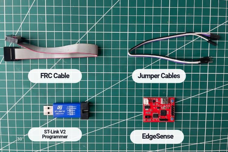
| S.no | Component | Purpose |
| 1. | EdgeSense Board | The main hardware contains the STM32 "brain" and the Time-of-Flight sensor. It captures depth data and runs the AI model locally. |
| 2. | ST-Link V2 Programmer | Programmer tool used to transfer the compiled firmware from your computer to the microcontroller. |
| 3. | USB Type-C Cable | The physical wires used to connect the ST-Link V2 programmer to the debug pins on the EdgeSense board. |
| 4. | Jumper Cables | Provide power to the board, program the board and handle the high-speed data streaming between the board and the Python visualizer. |
Normal ToF vs VL53L8CH Multizone ToF Sensor
Like other ST multizone sensors, the VL53L8CH sends out infrared light and calculates distances across an 8×8 grid based on the time taken for the reflected light to return. However, while standard ST Time-of-Flight sensors only output these final processed distance values, the VL53L8CH also streams the raw infrared reflection waveforms (histograms), enabling AI models to classify materials, detect transparent objects, and recognise complex gestures.
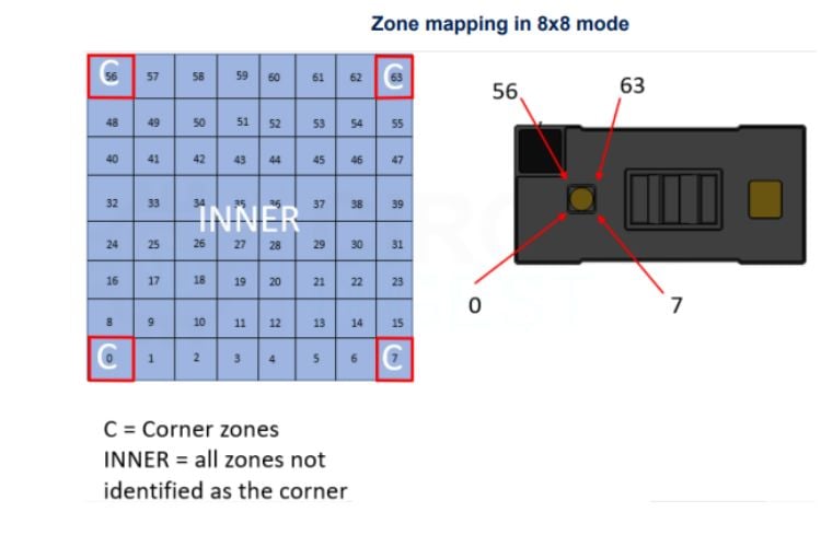
In its 8×8 mode, the sensor divides its field of view into 64 zones and provides a separate distance measurement for each zone. This creates a small depth map of the scene, helping EdgeSense understand not just whether a hand is present, but also its position, shape, and movement within the sensing area.For example, when a user swipes from left to right, the distance pattern changes across the zones in a different sequence than it does during an upward or downward swipe. Similarly, different hand positions and postures can produce different depth patterns, which the system can use to classify gestures. This allows EdgeSense to recognise several types of hand movements without requiring a camera to capture conventional images of the hand.
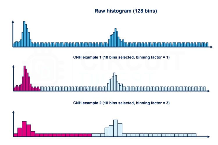
The VL53L8CH also supports a 4×4 mode, which provides 16 distance zones and can supply a 48-bin signal histogram. A histogram is a representation of measured signal information grouped into ranges called bins, with each bin representing a small interval of the returned-light signal. The sensor records how much signal falls within these intervals, creating a pattern that provides information about how infrared light reflects from a surface. This information can help EdgeSense distinguish between different surfaces based on their signal responses. By combining multi-zone depth measurements with this additional signal information, EdgeSense can support both gesture recognition and surface classification using a single compact sensor.
EdgeSense Circuit Diagram and Hardware Design
STM32H533CEU6 Microcontroller
We used the STM32H533CEU6, an ARM Cortex-M33 microcontroller running at up to 250 MHz. It serves as the brain of the system, handling sensor communication, processing incoming data, and running trained neural-network models directly on the chip. The project uses ST's X-CUBE-AI software to deploy the trained models, enabling EdgeSense to recognise hand gestures and classify surfaces locally without sending data to a cloud server.
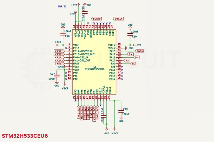
The STM32H533 is paired with the VL53L8CH multizone Time-of-Flight (ToF) sensor, which provides the depth and reflected-light information used by these models.
VL53L8CH Multizone Time-of-Flight Sensor Interfacing
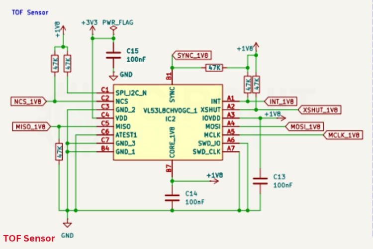
The VL53L8CH Time-of-Flight sensor interfaces with the STM32H533 microcontroller via dedicated power, control, and high-speed communication lines to support distance measurement and AI processing. Powered by regulated 3.3V and 1.8V supplies stabilised by decoupling capacitors, the sensor uses a 3MHz SPI interface and GPIO control pins to configure registers and transfer measurement data. To optimise efficiency, the sensor sends a hardware interrupt signal via the INT pin whenever new data is ready, eliminating continuous polling and freeing the STM32H533 to manage sensor acquisition alongside real-time AI inference.
ST2378E Logic Level Shifter
The STM32H533 and VL53L8CH operate at different digital logic voltages. The microcontroller uses 3.3V logic, while the sensor's digital interface operates at 1.8V. To connect these devices safely, the circuit includes an ST2378ETTR 8-bit bidirectional level shifter.
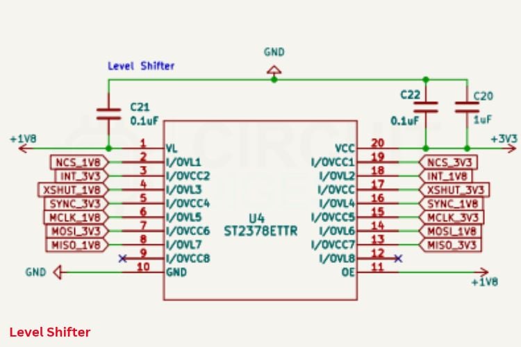
It translates digital signals between the two voltage domains, allowing signals to pass between the microcontroller and sensor at compatible logic levels. This is important because connecting devices with different logic voltages directly, without checking their electrical requirements, can lead to communication problems or damage.
Power Supply and Li-Po Battery Charging
The board supports two power options: a 5V supply through USB Type-C or an external 3.7V single-cell Li-Po battery. An L6924D013TR charging IC manages the Li-Po battery charging process. The power circuit uses an ST1L08SPU33R 3.3V low-dropout regulator for the microcontroller supply and an LD1117V18 1.8V regulator for the ToF sensor.
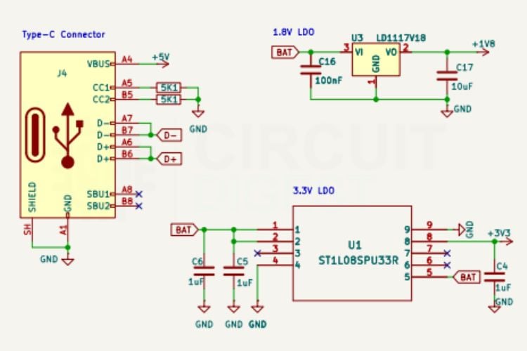
These components provide the voltage levels required by the respective devices. The separate supply rails allow the board to accommodate the different power requirements of the microcontroller and sensor.
USB Communication and SWD Debugging
The USB Type-C connector is also connected to the STM32's native USB interface, which can operate as a USB virtual COM port. This allows EdgeSense to exchange data with a computer and stream sensor readings for monitoring and visualisation during development.
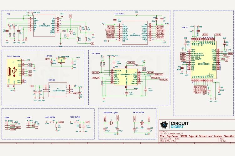
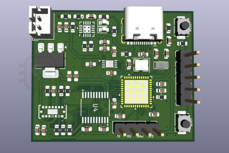
The PCB also includes a dedicated five-pin ST-Link Serial Wire Debug (SWD) header, providing access to SWDIO, SWCLK, NRST, power, and ground. A compatible ST-Link debugger can use this interface to program the microcontroller, set breakpoints, inspect variables, and troubleshoot firmware execution.
How to Connect the EdgeSense Board for Programming
Setting up the EdgeSense board takes just two quick steps. First, connect a USB Type-C cable to the port on the board; this powers the board and creates a 921,600 baud Virtual COM port to stream live AI predictions and receive AT commands from your PC. Second, connect an ST-Link V2 programmer to the 5-pin J3 SWD header using jumper cables: wire J3 Pin 1 to 3.3V, Pin 2 to Ground, Pin 3 to Reset, Pin 4 to SWDIO (STM32 pin 34 / PA13), and Pin 5 to SWCLK (STM32 pin 37 / PA14). Once the two cables are connected to the PC’s ports, the power LEDs will light up; your hardware is ready for flashing from STM32CubeIDE.For programming, you need both cables connected, but to check and see the output, just the Type-C USB Cable is enough.
Firmware and Software Setup for STM32 Edge AI
To set up the software environment for EdgeSense, you begin by installing the required embedded development toolchain and Python environment. First, download and install STM32CubeIDE (version 2.2.0 or newer), which includes the integrated GNU ARM GCC toolchain and GDB debugger for compiling C code. Next, install STM32CubeMX, which is a graphical software configuration and initialisation code generator tool by STMicroelectronics. Once the prerequisites are ready, download or clone the complete EdgeSense project repository from Circuit Digest GitHub to your computer. You can refer to the link above. Then, on the host computer side, install a 64-bit Python 3.10+ environment and install the required dependencies, including PyTorch, NumPy, PyQt5, and PySerial, by navigating to the project's studio directory and running pip install -r requirements.txt.
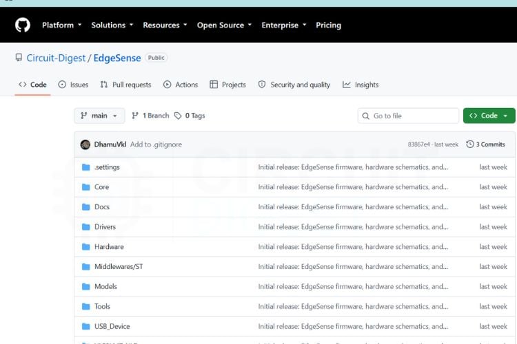
With the software tools installed, open STM32CubeIDE, navigate to File -> Import, select "Existing Projects into Workspace", and browse to your downloaded EdgeSense repository folder. After importing the project, locate and double-click the EdgeSense.ioc file in the project explorer to launch STM32CubeMX directly inside the IDE.
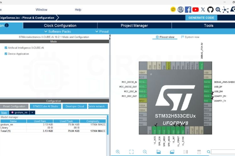
In the STM32CubeMX pinout and configuration editor, the peripherals are pre-configured for high-speed spatial sensing. Under System Core, the High-Speed External (HSE) clock source is set to a 24 MHz external crystal oscillator to supply a precise system clock. The SPI1 peripheral is configured in Full-Duplex Master mode running at 3 MHz with an 8-bit data frame format to handle high-bandwidth photon histogram data streaming from the VL53L8CH Time-of-Flight sensor. Additionally, a dedicated GPIO line is assigned to an External Interrupt (EXTI) trigger linked to the sensor's data-ready pin so that the microcontroller processes incoming depth matrices asynchronously without wasting CPU cycles on continuous polling. Under Middleware, the USB Device stack is configured in Communication Device Class (CDC) mode to establish a high-speed Virtual COM Port operating at 921,600 baud for data streaming, while SYS Debug is set to Serial Wire for SWD debugging. Then, in the clock configuration section, check the input frequency is 24MHz and then because we already created the firmware part, we don't need to generate the code again . Now close the STM32CubeMX and again enter into our Project folder in the STM32CUBEIDE.
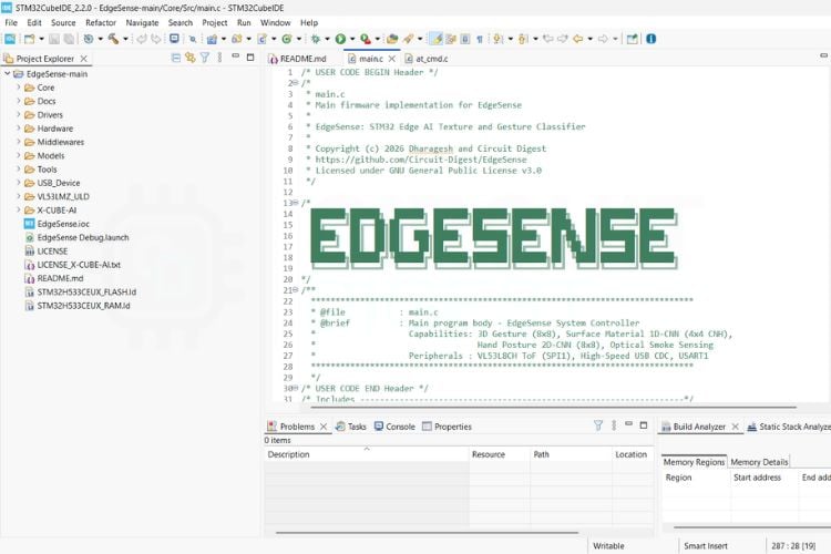
Looking inside the generated C codebase under Core/Src/main.c, the firmware execution loop begins by bootstrapping the system clocks, USB stack, SPI peripherals, and HAL drivers. Right after boot, the firmware invokes the InitSensor() routine, which initialises the VL53L8CH Time-of-Flight sensor, calibrates baseline noise levels, and loads active ranging profiles. These profiles dictate spatial resolution (such as 8x8 matrix mode for gestures and hand postures or 4x4 matrix mode for surface classification) as well as enabling Compact Normalised Histogram (CNH) bin collection.
To make the device easy to control without rewriting or re-uploading the code every time, the project includes a built-in AT command system in
at_cmd.c that listens over the USB cable just like a simple serial chat. By sending plain text commands, host programs or computer apps (such as the Python Visualizer) can control the board in real time. For instance, sending AT+STATUS? checks how the board is doing, returning the current operating mode, live frame rate (FPS), and how fast the AI chip made its last prediction. To switch what the device is detecting, you simply send AT+MODE=GESTURE, AT+MODE=POSTURE, or AT+MODE=SURFACE. Whenever you switch modes, the firmware automatically re-tunes the sensor to match: gesture and posture modes switch the sensor to an 8x8 grid (64 points) to track hand movements smoothly across the field of view, while surface texture mode switches it to a 4x4 grid with finer light-histogram detail (48 bins) to analyse how laser light bounces off materials like carpet, wood, or metal. You can also tell the board what kind of data to send back over the USB connection using AT+STREAM. Setting it to RAW (AT+STREAM=RAW) sends all live distances and light histogram numbers for live graphing and recording training data, while setting it to RESULTS (AT+STREAM=RESULTS) tells it to send only the final AI detection (such as "Swipe Left: 96% confidence") to keep the output clean and lightweight. Finally, simple commands like AT+PAUSE and AT+RESUME allow you to temporarily stop and restart the laser sensor whenever needed.
How to Train the Gesture, Posture and Surface AI Models
The EdgeSense project uses three separate neural-network models: a Gesture 2D-CNN(Convolutional Neural Network), a Surface 1D-CNN, and a Posture 2D-CNN, all trained directly from sensor data collected live from the board. A custom desktop tool called EdgeSense Neural Network Studio handles everything from data recording to MCU flashing in one window. Launch it by running python Tools/Studio/edgesense_nn_studio.py or by double-clicking Tools/Studio/run_nn_studio.bat. Before the first launch, install the required packages with pip install -r Tools/Studio/requirements.txt.
Connect the board. Select the EdgeSense COM port from the dropdown and click Connect. The Studio opens a 921,600-baud USB CDC link to the board and immediately begins streaming live sensor data into the heatmap view.
Training the Gesture Recognition Model
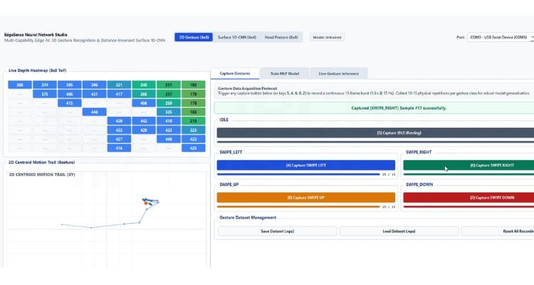
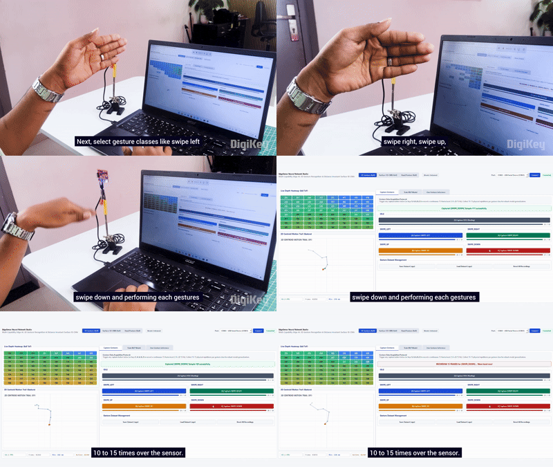
Let's start with the Gesture Recognition model. Switch to the GESTURE tab and record five classes: IDLE, SWIPE_LEFT, SWIPE_RIGHT, SWIPE_UP and SWIPE_DOWN. Click each capture button and perform the corresponding gesture within the one-second recording window. Record at least 10 samples for each class, varying your hand height between 10 and 40 centimetres and changing the speed of your movements. After completing all the movements, click the train option.
But how does the model actually learn to recognise these gestures? The VL53L8CH operates in 8×8 mode, providing 64 distance measurements for every frame. These measurements form a depth map of the area in front of the sensor. When you move your hand, the distance values change across different zones. For example, during a left-to-right swipe, the hand appears in one group of zones first and then moves across the sensor grid. A swipe in the opposite direction produces a different sequence of distance patterns.
The Gesture model uses a 2D Convolutional Neural Network, or 2D-CNN, to learn these spatial and movement patterns from the recorded depth data. During training, every recording is associated with its correct gesture label, allowing the network to learn which patterns belong to each class. It does this by adjusting its internal weights to reduce the difference between its predictions and the correct labels. The Studio also balances the training classes and generates seven augmented variations of the recorded samples to introduce more variation into the training data. It then trains the network for 35 epochs using the AdamW optimiser. Once training is complete, the model is evaluated using validation data, and its validation accuracy and confusion matrix are displayed in the log. The trained model is then exported as an ONNX file.
Training the Surface Classification Model
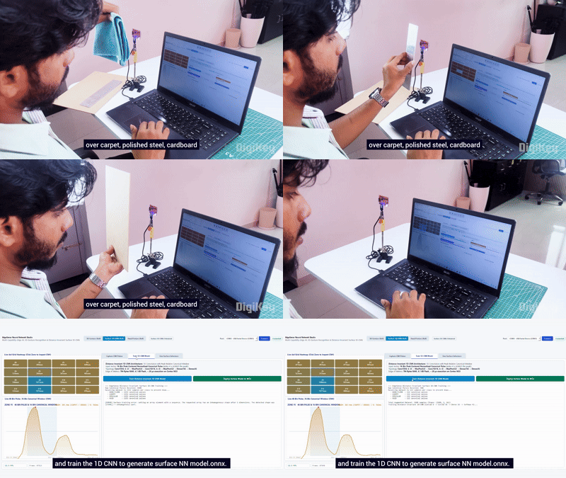
Next, let's train the Surface Classification model. Switch to the SURFACE tab and point the sensor between 10 and 40 centimetres above each material. Use Burst Capture to record at least 50 samples for each of the four classes, which are Hard Floor, Carpet, Specular and Void, in front of the sensor. Then, after collecting the 50 samples for each material, click Train.
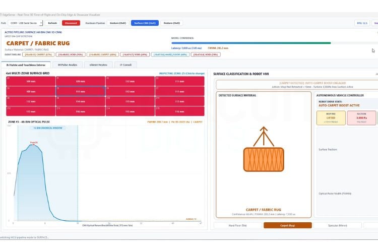
Unlike the gesture model, which learns movement patterns from changing distance measurements, the surface model studies how infrared light reflects from different materials. For this, the sensor switches to 4×4 mode and collects a 48-bin signal histogram. You can think of this histogram as a graph showing how the returning infrared signal is distributed across different intervals. Different surfaces produce different reflection patterns. Carpet scatters the infrared light across a wider range because of its fibres, while hard surfaces such as wood and tile generally produce a cleaner reflection. Shiny surfaces such as polished steel and mirrors can produce a strong, sharp reflection, whereas a void produces little or no useful returning signal.
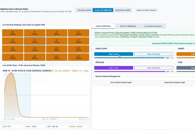
Before training, the Studio processes each recorded sample and extracts a distance-invariant, 16-bin canonical pulse window. This converts the reflection information into a standardised one-dimensional signal pattern. The Surface model uses a 1D Convolutional Neural Network, or 1D-CNN, to analyse the shape and distribution of this signal. During training, it learns the differences between the patterns associated with the four surface classes. The Studio generates five augmented variations of the samples and trains the network for 40 epochs. After training, the model is exported as an ONNX file.
Training the Hand Posture Detection Model
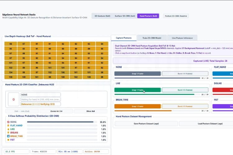
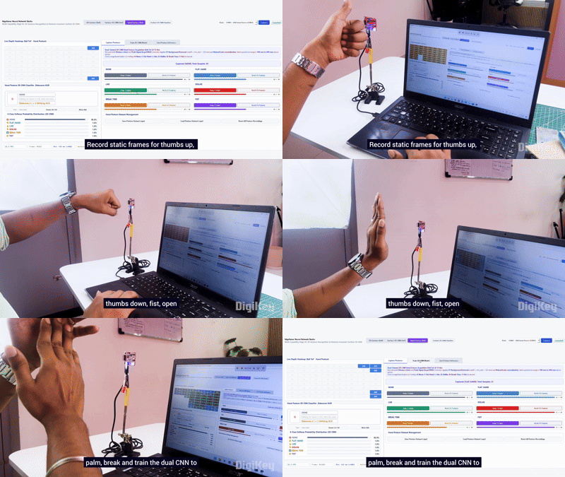
Finally, let's train the Hand Posture model. Switch to the POSTURE tab and hold each hand posture steadily between 10 and 40 centimetres above the sensor. Record 20 to 30 samples for each of the six classes: NONE, FLAT_HAND, LIKE, DISLIKE, BREAK_TIME and FIST. Then click Train.
The interesting part of this model is that it uses two types of sensor information together. The first is the distance map, which tells the model how far the hand is from each of the 64 sensor zones. The second is signal intensity, which represents the strength of the reflected infrared light from those zones. The Studio combines these measurements into a two-channel 8×8 input, giving the model two different views of the same hand: one showing its distance pattern and the other showing its reflected-light pattern.
The Posture model uses a 2D Convolutional Neural Network to learn the spatial patterns associated with different hand shapes. For example, an open palm produces a different distance and signal-intensity pattern compared with a closed fist. Similarly, a thumbs-up and thumbs-down produce different patterns that the network learns to distinguish during training. The Studio applies seven augmentation variations, including horizontal flips and spatial shifts, to introduce more variation into the training data. It then trains the network for 35 epochs. Once training is complete, the posture model is also exported as an ONNX file
How to Deploy the ONNX Model to STM32 with STM32Cube.AI
To deploy the trained neural network models onto the microcontroller, start by launching STM32Cube.AI Studio and logging in with your STMicroelectronics account. Create a new project, select the STM32H5 family, specify the target MCU part number as STM32H533CEU6, and configure STM32CubeIDE as the official target toolchain.
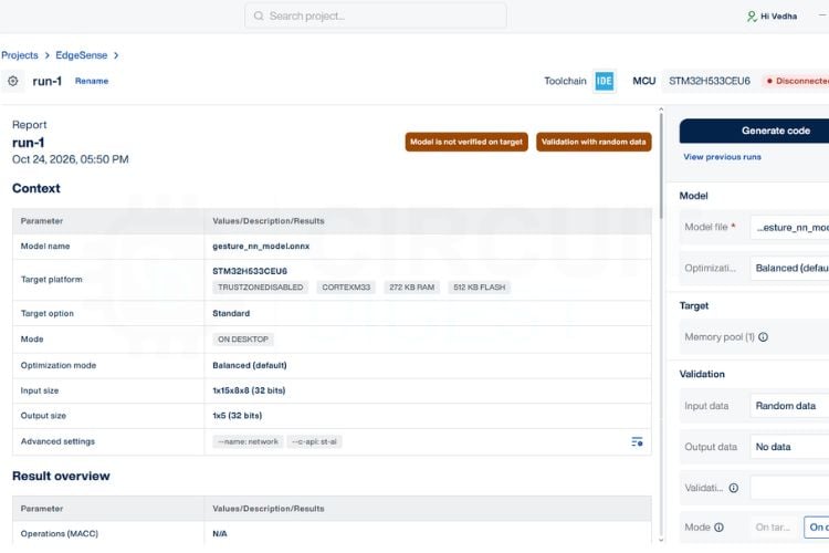
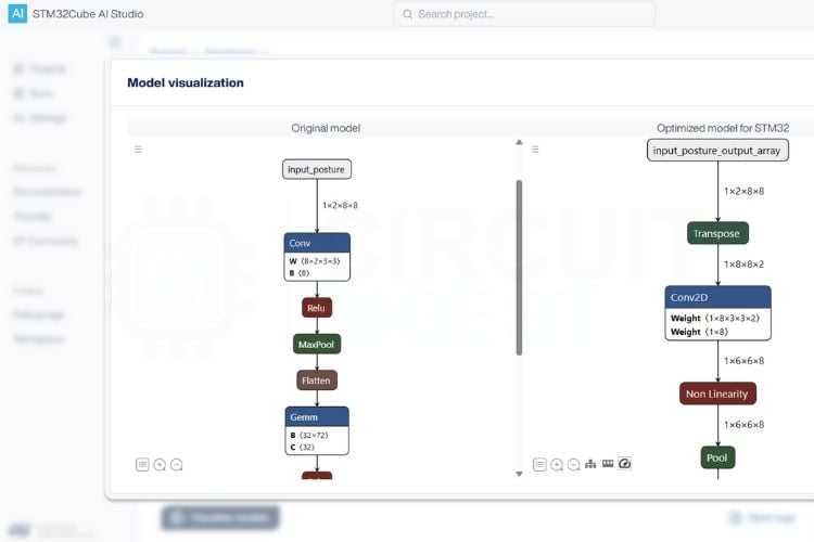
Under the Model section, import the trained ONNX model located in the Models directory of the EdgeSense repository (such as gesture_model.onnx, posture_model.onnx, or surface_model.onnx), assign the appropriate model identifier, and click Run to execute the hardware profiling engine. The resulting analysis report details the model's complexity, inference MACC operations, validation accuracy, Flash consumption for weights, and required RAM activation buffers, while clicking Visualise Model displays a graphical comparison between the original and optimised compute graphs.
Next, click Generate Code at the top bar, followed by Generate C Code to produce the optimised C source files, header definitions, and constant weight tables. Once generation completes, click Download your C model to save the generated zip archive directly to your Windows Downloads directory. To transfer the files into your embedded project, navigate to the Project workspace EdgeSense\Tools\Studio\utils\ and execute import_cubeai_zip.bat. The script automatically identifies the latest archive in Downloads, resolves the model type, and extracts all required C/H files into EdgeSense\X-CUBE-AI\App\. Finally, open STM32CubeIDE, connect your STM32H533 target hardware via ST-LINK USB, and click Run to flash the firmware and initiate on-device edge AI inference.
Testing the STM32 ToF Gesture Recognition System
Once everything is flashed, connect the EdgeSense board to a computer and run the EdgeSense_python_visualizer.py script. Here, the computer is not doing the heavy processing. The STM32 chip on the board reads the sensor data, runs the neural network, and sends the final result to the computer for display.
After running the Python script, a new window will open. Select the correct COM port and click Connect. The system will then start working. By default, it starts in Gesture Recognition Mode. Now, let’s look at each mode and see what happens.
Gesture Recognition Mode
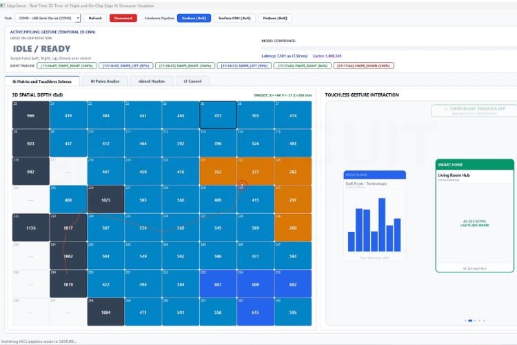
In Gesture Recognition Mode, the Time-of-Flight sensor uses an 8×8 spatial resolution and captures depth data at 15 frames per second. The firmware continuously takes a group of these frames and sends them to the neural network for recognition.
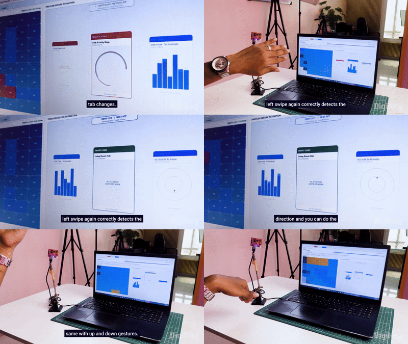
Now, if I swipe my hand to the left, the system detects the movement and changes the box and cursor on the screen to show a left swipe. The same happens for right, up and down movements. The detected gesture and the model’s confidence percentage are shown on the screen.
We have created a demo script that detects swipes, which can be used to control applications. For example, in the demo script, swiping left moves to the previous tab, while swiping right moves to the next one. Up and down gestures can also be used to navigate through the interface.
This type of gesture recognition could be useful for touchless interfaces, where users can control applications or devices without physically touching them.
Surface Classification Mode
Next is Surface Classification Mode. In this mode, the sensor switches to a 4×4 grid and enables a 48-bin histogram. Instead of just measuring distance, the system looks at how the light bounces back from the surface to identify what it is:
| S.No | Material | Details |
| 1. | CARPET | When light hits cloth or carpet, it goes into the fibers and scatters, creating a wider, stretched-out light pulse. |
| 2. | HARD_FLOOR | Hard surfaces like wood, tile, or cardboard bounce light back cleanly in a sharp, normal pulse. |
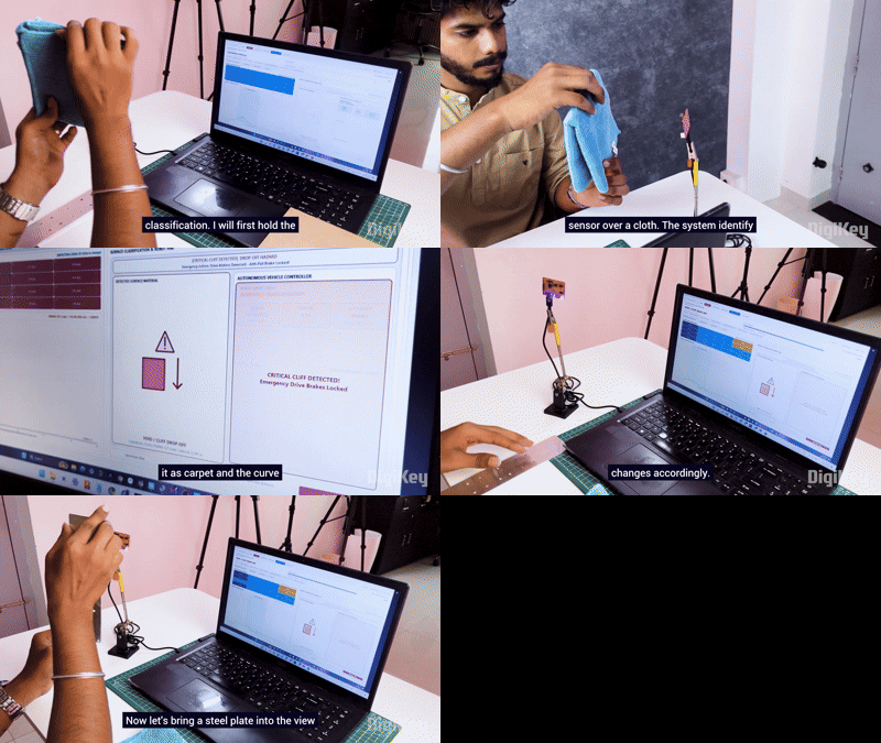
| 3. | SPECULAR | Shiny surfaces like a steel plate or mirror bounce almost all the light straight back like a flashlight into a mirror, creating a very strong, sharp spike. |
| 4. | VOID | When the sensor is held over a table edge or cliff, the light does not come back at all, and the system detects a drop-off. |
Important Limitations to Know:
The sensor is looking at how light reflects, not what the material is made of chemically. For example, a shiny glass mirror and shiny steel look the same to the sensor because both reflect light directly. Also, the mirror or steel must be directly facing the sensor. If you tilt the sensor too much, the reflected light bounces away to the side, and the sensor will think it sees space (VOID). In real projects like robot vacuums, this is great for telling tile from carpet and avoiding stairs.
Hand Posture Detection
The next mode is Hand Posture Detection. This mode uses a dual-channel 2D-CNN to analyse both the depth map and signal intensity from the sensor's 64 zones.
Here, when I hold a flat hand above the sensor, the system recognizes it as FLAT_HAND. A thumbs-up is detected as LIKE, while a thumbs-down is detected as DISLIKE. A closed hand is recognised as FIST. When I remove my hand, the system returns to NONE.
This could be useful for touchless controls, such as smart-home interfaces or kiosks. For example, the demo shown here can use different hand postures to control the music player shown on the screen.
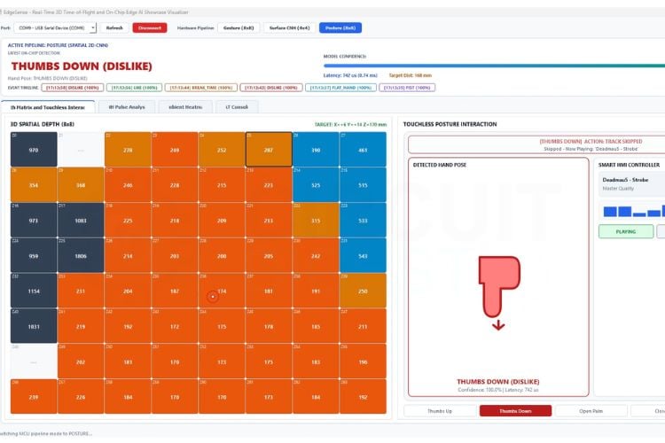
The system can perform the neural-network inference in less than 7 milliseconds per frame. This makes EdgeSense a good example of Edge AI, where the data is processed locally instead of being sent to the cloud. That means the system can work without an internet connection while providing fast responses on a small embedded device.

Conclusion
So, the main takeaway is pretty simple: we are teaching an embedded microcontroller how to "see" and "think" all by itself. Normally, to do something this smart, you would need a powerful computer or an internet connection. But with EdgeSense, the board does all the hard work locally. It uses a tiny TOF sensor to look at the space in front of it and figure out exactly what it is seeing, whether that's a waving hand, a thumbs up, or the type of floor it’s pointing at. It’s a perfect example of making everyday objects much smarter without needing big, expensive parts. EdgeSense shows that STM32 ToF sensor gesture recognition doesn't need a camera, a powerful computer or an internet connection