
Optocouplers frequently fail without a sound in labs or during repairs. The package appears to be undamaged, but there may be no output from the LED source or the photosensitive output stage. Testing for failure with a multimeter is only partially effective, whereas a dedicated optocoupler testing circuit provides clear results in just seconds. For related tutorials and step-by-step build guides, explore Circuit Digest's Electronic Circuits hub.
Table of Contents
- What is an Optocoupler Tester Circuit?
- What does an Optocoupler Tester Check?
- Components Required
- Circuit Diagram and Schematic
- └ How to Read the Schematic
- How the Optocoupler Tester Works
- Working Demonstration
- Alternate Methods to Test the Optocouplers
- Comparison
- └ Optocoupler Tester vs. Multimeter Method
- Advantages and Disadvantages
- Troubleshooting
What is an Optocoupler Tester Circuit?
An optocoupler tester is a small device that helps verify whether an optocoupler is functioning properly or has failed. In labs and repair work, optocouplers often fail without clear signs. They may look fine from the outside, but the internal LED or photo part may not function properly. Guessing in such cases wastes time and can damage the main circuit. This tester dispels that doubt by checking whether the internal LED turns on and whether the output side responds to light. The circuit stays simple, runs on a 3.7 V lithium-ion battery, and can be built on a dot board without using any measuring tools. It does not aim to test detailed performance, but it works well for quick and reliable checks at the workbench. More details about the Optocoupler and its applications are provided on the Optocoupler tutorial page. Also, you can explore more applications and other electronic circuits on our resources page.
What does an Optocoupler Tester Check?
∗ The IR LED at the input side is conducting and producing light (IR emission)
∗ The Photodetector at the output side is triggering due to the IR light that the IR LED is producing
∗ The testing circuit is able to conduct both a 4-pin DIP and a 6-pin DIP with no wiring changes being required.
Components Required to Build the Optocoupler Tester
The image below shows the list of components used to build the Optocoupler Testing circuit.
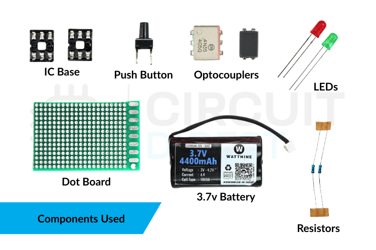
The circuit uses only commonly available components. It avoids special or complex parts, making it easy to build and understand. The table shows every component used in this DIY optocoupler tester build.
| Component | Quantity | Function in Circuit |
| Optocoupler | 1 | To use it as a test component |
| Red LED | 1 | Indicates power to the optocoupler input |
| Green LED | 1 | Indicates the output response of the optocoupler |
| Push Button | 1 | Turns the tester ON during checking |
| Li-ion Battery | 1 | Supplies power to the circuit |
| 470 OhmResistor (R1) | 1 | Limits the current to the optocoupler input LED |
| 470 Ohm Resistor (R2) | 1 | Limits the current to the output indicator LED |
| IC Base (4-pin) | 1 | Holds 4-pin optocouplers for testing |
| IC Base (6-pin) | 1 | Holds 6-pin optocouplers for testing |
| Dot Board | 1 | Mounts and connects all components |
The circuit uses IC bases instead of soldering optocouplers directly. This avoids heat damage and allows the same tester to be used repeatedly with different optocouplers.
Optocoupler Tester Circuit Diagram and Schematic

How to Read the Schematic
The optocoupler tester schematic consists of two main sections: the input and output parts of the optocoupler. On the input side, the Li-ion battery supplies power via a resistor, and the push button determines when the power is delivered. When the button is pressed, current flows through the optocoupler's internal LED, causing the red LED to light up, indicating that the input side is receiving power and is functioning.
On the output side, the light from the internal LED reaches the light-sensitive component inside the optocoupler. This allows current to flow through the green LED, turning it on and showing that the output side is working correctly. Both the input and output sides are connected to the same ground. This optocoupler tester circuit is constructed on a dot board with IC bases. The optocoupler tester circuit diagram shows that this configuration enables testing of both 4-pin and 6-pin optocouplers without changes to the wiring.
How the Optocoupler Tester Works
Understanding the optocoupler tester working principle requires only three concepts: IR LED emission, phototransistor activation, and current-limited indicator LEDs. The optocoupler tester works based on optical isolation. When you press the button, power flows to the input LED inside the optocoupler. If everything is working properly on the input side, the internal LED lights up and the red LED turns on to indicate that current is flowing correctly.
The light from the input LED then reaches the light-sensitive part on the output side of the optocoupler. This allows current to flow through the green LED, causing it to glow and indicating that the output side is working correctly. This optocoupler test helps you quickly identify issues. If only the red LED turns on, it means there's a problem with the output side or the light isn't transferring properly. If neither LED turns on, the input LED may be faulty, or the optocoupler may not be connected correctly.
| Red LED | Green LED | Test Result | Action |
| ON | ON | PASS — Good optocoupler | Safe to use in a circuit |
| ON | OFF | FAIL — Output stage dead | Replace the optocoupler; the phototransistor is damaged |
| OFF | OFF | FAIL — Input LED open or wrong insertion | Check pin orientation; replace if correct |
| OFF | ON | SUSPECT — Output shorted or wiring error | Check tester wiring; the output transistor may be shorted CE |
Practical Working Demonstration
In real use, insert the optocoupler into the correct IC socket and verify that it is positioned properly. Then press the button to activate the circuit. A working optocoupler will light up the red LED immediately, showing that the input side is active, followed by the green LED, which confirms that the output side is responding. If only the red LED lights up, the optocoupler is faulty and should not be used. If neither LED turns on, the device may be damaged or inserted incorrectly. This DIY optocoupler tester is especially useful when checking salvaged components or verifying a batch of parts. To better understand why optocouplers are used for electrical safety and isolation, you can read more about galvanic isolation.
Alternate Methods to Test the Optocouplers
Different methods are used to test an optocoupler, depending on the tools available and the level of accuracy required. A multimeter can quickly check the internal LED, and simple testing circuits built on a breadboard can show how the input and output work. For more detailed testing, labs use advanced tools such as component testers and curve tracers. Here are the commonly used testing methods.
1. Comparison Method
In this method, the optocoupler suspected of being faulty is removed from the circuit and tested with a multimeter. Then, the readings from the multimeter are compared with those from another optocoupler known to be working properly and of the same type. The test measures the forward and reverse resistance of the internal LED and the resistance between the transistor pins. If the measured values differ significantly from those of the good optocoupler, the tested optocoupler is likely damaged. This approach is straightforward and fast, but it only gives a general idea and does not guarantee that the device will work correctly in real situations.
2. Digital Multimeter Detection Method
This is the most widely searched approach. Here is a structured procedure for how to check an optocoupler with a multimeter:
A digital multimeter can be used to test both the input and output parts of a circuit separately. To start, check the input LED using the diode setting to make sure it conducts properly when forward-biased. Next, measure the output pins while the LED is on to see whether the transistor switches on or if there is a change in current or gain. If the readings change when the input is activated, the optocoupler is working correctly; if there is no change, it may be faulty. This method provides more detailed information than a simple resistance check, but the setup and results can be confusing for someone new to electronics and still need some interpretation.
3. Photoelectric Effect (Battery and Resistor) Method
This method directly tests the optocoupler's working principle by powering the input LED with a small battery and a current-limiting resistor, while monitoring the output pins with a multimeter. When the LED turns on, the light inside the device should activate the output transistor, causing the meter reading or pointer to change. If the reading changes or the pointer deflects, the optocoupler is working; if there is no change, the device is defective. Because it checks real input-to-output behaviour, this method is more reliable and practical than simple resistance measurements.
Comparison Between the Optocoupler Tester and Multimeter Method
Using a Multimeter
A multimeter is convenient because it is already available in most labs and does not require any extra hardware. It can check basic things like LED continuity and diode behaviour, which helps with a quick preliminary inspection. However, it only tests the input LED of the optocoupler and cannot verify the output side properly. This means the device may appear fine even when it is actually faulty. The process also involves manual probing and interpretation of readings, which can be slow and confusing for beginners. As a result, a multimeter provides only a rough estimate rather than a clear confirmation.
Using an Optocoupler Tester
An optocoupler tester circuit is designed specifically for testing optocouplers and checks both the input LED and the output transistor simultaneously. It directly shows whether the device is working or faulty using simple LED indicators, so no probing or analysis is required. The test is fast, easy, and reliable, making it suitable even for first-year students or beginners. The only disadvantage is that an extra circuit must be built or purchased, but once it's available, it provides a clear, accurate optocoupler test every time.
Optocoupler Tester vs. Multimeter Method
| Criterion | Dedicated Optocoupler Tester | Digital Multimeter |
| Tests input LED | ✔ Yes | ✔ Yes (diode mode) |
| Tests output phototransistor | ✔ Yes- simultaneously | Partial - requires extra setup |
| Result readability | Instant LED pass/fail | Numerical values need interpretation |
| Test speed | <2 seconds per device | 2–5 minutes for the full 3-step test |
| Additional hardware needed | The tester itself (~₹50 / $1 in parts) | Multimeter already in the lab |
| Detects partial output degradation | Only gross failures | Only gross failures (without scope) |
| Suitable for batch testing | ✔ Yes — very efficient | ✘ No — too slow |
Advantages and Disadvantages of the Optocoupler Tester
| Advantages | Disadvantages |
| Checks optocouplers quickly without using any instruments | Does not show the output signal strength |
| Small size and runs on a battery | Not useful for very fast or special optocouplers |
| Works with both 4-pin and 6-pin optocouplers | Cannot clearly find weak or ageing optocouplers |
| LED lights make the result easy to see | Only checks basic working conditions |
| Low cost and easy to build again | Not meant for detailed testing |
Troubleshooting Optocoupler Testing Issues
These are some troubleshooting methods for optocoupler testing issues
| Problem Observed | Possible Cause | Solution |
| The input LED is not glowing. | Wrong pin connection or reversed polarity | Check the pinout and reconnect correctly |
| Input LED ON, but no output response | Output transistor damaged | Replace the optocoupler |
| No diode reading in the multimeter test | Internal LED open | Replace the optocoupler |
| Output always ON or always OFF | Wiring mistake or short circuit | Inspect and correct connections |
| The tester is not working or is showing unstable readings | Low battery or loose contacts | Replace the battery and secure connections |
Frequently Asked Questions About Optocoupler Testing
⇥ Can an optocoupler be tested using only a multimeter?
Yes, but only partially. A multimeter can check the internal LED using diode mode, but it cannot fully verify whether the output side is working. It provides a basic check, not a complete functional test.
⇥ Why is a dedicated optocoupler tester better than a multimeter?
An optocoupler tester checks both the input LED and the output transistor simultaneously. It provides a clear pass-or-fail result instantly, making testing faster, easier, and more reliable.
⇥ What is the simplest way for beginners to test an optocoupler?
Using a small optocoupler tester circuit with LEDs is the easiest method. It requires no calculations or measurements and shows the result visually.
⇥ Can an optocoupler look normal but still be faulty?
Yes. Physical damage is rarely visible. The internal LED or photo-transistor may fail even when the package looks perfect. That is why functional optocoupler testing is necessary.
⇥ Is a breadboard test circuit enough for learning purposes?
Yes. A simple breadboard-based optocoupler testing circuit is good for understanding how the device works. However, for regular lab or repair work, a dedicated tester is more efficient.
Conclusion
This optocoupler tester circuit gives a simple and reliable way to check whether 4-pin and 6-pin optocouplers are working. The LED indicators clearly indicate whether the input side receives power and whether the output side responds correctly. The small, battery-powered design makes it useful for quick checks during assembly, learning, or repair work. This optocoupler tester circuit diagram focuses on basic working checks rather than detailed electrical testing. It helps detect faulty optocouplers early, saving time and preventing mistakes during installation. The tester delivers consistent, practical results without unnecessary complexity. Find practical, real-world Electronics Projects and step-by-step tutorials at this resource hub
Projects Using Optocoupler Isolation
These projects demonstrate how optocouplers provide safe electrical isolation between high-voltage AC circuits and low-voltage electronics. They are used for applications like zero-cross detection and AC power control in embedded systems.

Adaptive Musical Instrument for Physically Challenged Persons
An AI-based system that analyses ECG signals and vital parameters to predict heart disease, while also featuring an adaptive musical instrument that allows physically challenged individuals to create music through simple sensor-based interaction.

Zero-Crossing Detector Circuit
A Zero Crossing Detector circuit uses an op-amp (such as the LM741) as a comparator to detect when an AC signal crosses zero, converting the sine-wave input into a square-wave output for applications such as frequency measurement and phase control.

AC Fan Speed Control using Arduino and TRIAC
An Arduino-based AC fan speed controller that uses a TRIAC and zero-crossing detection to adjust the phase angle of the AC signal, allowing the fan speed to be varied using PWM and a potentiometer.
