
OR Gate

|
How does a Two Way Switch Work - Wiring Connection and Demonstration One of the simple yet interesting connection diagrams that young engineers learn in their lab is the staircase lighting setup. Perhaps most of us might have already used it without paying much attention to how it works. Staircase lighting at home or at any other place, for that matter, is normally done with something called a two-way switch. … |

|
Designing OR Gate using Transistor As many of us know an Integrated Circuit or IC is a combination of many small circuits in a small package which together performs a task. Like an Operational Amplifier or 555 Timer IC is built by a combination of many Transistors, Flip-Flops, Logic Gates and other combinational digital circuits. Similarly a Flip-Flop can be built by using a combination of Logic Gates and the… |
|
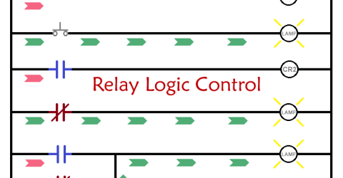
Introduction to Relay Logic Control - Symbols, Working and Examples Relay logic control systems are truly a foundation of industrial automation, and electromagnetic relays are necessary to perform switching actions in these conversion systems. The relay logic circuits also utilise relays along with switches, motors, timers, actuators, and contactors to form ON/OFF control systems effectively. Though relay logic control proves to be effective… |

|
OR Gate OR gate is a digital logic gate, designed for arithmetic and logical operations. This gate is mainly used in applications where there is a need for mathematical calculations. Here we are going to use 74LS32 chip for demonstration, this chip has 4 OR gates in it. These four gate are connected internally as shown in below figure. … |