

One of the simple yet interesting connection diagrams that young engineers learn in their lab is the staircase lighting setup. Perhaps most of us might have already used it without paying much attention to how it works. Staircase lighting at home or at any other place, for that matter, is normally done with something called a two-way switch.
Now, there are many different types of switches in the market, and a few of them can be directly used for a 2 way switch wiring schematic without any special wiring connections. But in this tutorial, we will show you how to make a two-way switch wiring with normal household switches. A two way switching connection means you can control electrical equipment, like a bulb, with two switches placed at different locations, generally used in staircases.
Table of Contents
What is a Two Way Switch Connection?
A two way switch connection is an electrical circuit that allows you to control a single light or appliance from two different locations. A two way switch wiring can be operated from either switch independently, meaning that whatever the position of the other switch (ON/OFF), you can control the light with the other switch. There are two methods of making a two way switch connection diagram: one is the 2-wire control, and the other is the 3-wire control. We have explained both methods below, and both methods are demonstrated in the video given at the end of this article.
Primary Benefits of Two Way Switch Wiring
- Safer Light switch controls: You can control the lights without having to walk through a dark area.
- Convenient Light switch controls: You have a switch when entering and exiting the room.
- Energy efficient: Easy on/off control of mechanical devices may eliminate excess energy use.
- Flexible: Two way switch wiring is compatible with any electrical device: fans, motors, light bulbs.
Two Way Switch Connection Diagram: Understanding the Basics
From the start, we are using the word Two Way switch. Some might know, some not. Let’s see that in brief.
So, technically, a two-way switch is known as a Single Pole Double Throw (SPDT) Switch. Below, you can see some of the Types available in the market.
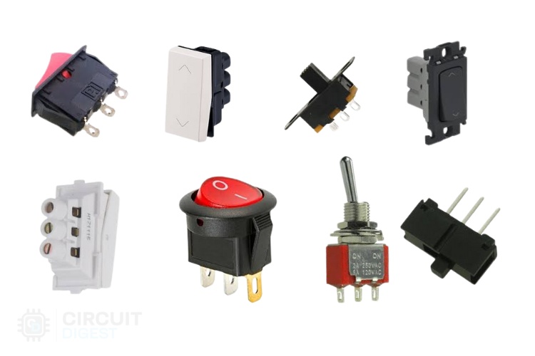
Some are used in DIY Projects, and some are used in Electrical projects. The following concept is Applicable to all types of applications, from Small DIY Projects to Complex Electrical Wiring Works.
Required Components for Two-Way Switch Connection
2-way switches x 2
Bulb x 1
AC supply x 1
Connecting wires
Two Way Switch Wiring with 2-Wire Configuration
This two way switch wiring schematic represents the traditional method:
This is the first method to make a two way light switch wiring; this is the old method. If you are going to install a new one, then go for three wire control methods.
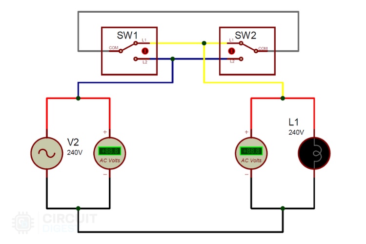
As you see in the 2 way switch wiring schematic below, you will find that the phase/live is connected with the common of the first 2-way switch. PIN1 & PIN2 of the first switch are connected with the PIN1 & PIN2 of the second switch, respectively. One end of the bulb is connected with the Common Terminal of the second switch, and another end of the Bulb is connected with the Neutral line of the AC power supply.
Note: In the 2-wire control method, when switches are in an opposite state, the light will be in the OFF state as shown in the circuit below:
The condition of getting Output in the ON condition is the same as the Ex-nor gate truth table, which is given below:
| Switch 1 (SW1) | Switch 2 (SW2) | Lamp state (L1) |
| OFF | OFF | ON |
| ON | OFF | OFF |
| ON | ON | ON |
| OFF | ON | OFF |
Two Way Switch Connection Diagram with 3 Wires
This is the new method to make a two way switch connection diagram with 3 wires, and it is slightly different from the two-wire control method. This method is commonly used nowadays as it is efficient than the Two-Wire control system.
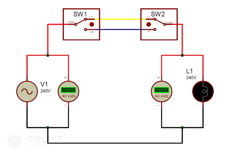
As you can see in the 2 way switch wiring schematic below, the common of both switches is short-circuited. PIN1 of both switches are connected with the phase or live wire, and PIN2 of both switches is connected with one end of the lamp. The other end of the Lamp is connected with the Neutral line of the AC power supply.
Note: In the 3-wire control method, when switches are in the same state, the light will be in the OFF state, as shown in the circuit below:
The condition of getting Output in the ON condition is the same as the EX-OR gate truth table, which is given below:
| Switch 1 (SW1) | Switch 2 (SW2) | Lamp state (L1) |
| OFF | OFF | OFF |
| ON | OFF | ON |
| ON | ON | OFF |
| OFF | ON | ON |
Advantages and Disadvantages of these Configurations
Advantages:
Allows control of any appliance from two different areas, regardless of the distance between them. Ideal for locations like staircases, large rooms, and bedrooms where control from multiple points is beneficial. Reduces the need to walk across dark areas to turn lights on or off, enhancing safety.
Disadvantages:
-Increased Wiring: Requires a significant amount of wiring, which can be more complex and costly to install. Diagnosing and fixing issues can be more challenging due to the additional wiring and switch points.
Applications of Two-Way Switch:
Staircases: For controlling lights from both the top and bottom of the stairs.
Erroneous Tripping of Safety/Circuit Protection Equipment: Helps in resetting tripped circuits from different locations.
Large Rooms with Multiple Entry/Exit Gates: Allows for convenient control of lighting or other equipment from different entrances.
Controlling AC Appliances (like fans or lights): Can be controlled from two places, such as the entry and exit points of a room.
Bedrooms: For controlling lights or fans from near the bed or while entering the room, providing convenience and flexibility.
Frequently Asked Questions on Two Way Switch Connection
⇥ In two way switch wiring, what is the difference between three and two wires?
The two-wire is achieved with traveller wires between switches (XNOR logic). The three-wire is achieved with both switches wired to live and load independently (XOR logic). The three-wire is used in new installations.
⇥ Is Wiring a Two-Way Switch Permitted?
You don't have to be an electrician to perform simple electrical work, but complicated tasks must be left to the professional. Whatever the case, follow your local electrical and safety codes. Don't forget to turn off the power before beginning any electrical task.
⇥ Why is my two-way switch not functioning properly?
The primary culprits of a two-way switch problem are shorted switches, improper wiring and poor connections. Inspect all connections; inspect the switch for continuity; and ensure the wiring diagram suits your installation method.
⇥ What Wire Gauge is Required for Two-Way Switch Wiring?
Apply 14 AWG to 15-amp circuits and 12 AWG to 20-amp circuits. Ensure the wire gauge meets your circuit breaker size and local electrical codes.
⇥ What is the longest distance for two way switches?
There is no limit, but increased wire runs equate to increased voltage drop and increased cost of installation. Low-voltage or smart switch technology is recommended for very long distances.
Innovative Applications of Electrical Switches
Discover projects built around switch applications, from simple control circuits to advanced automation systems, highlighting their role in everyday electronics.

What is Switch Bouncing and How to prevent it using Debounce Circuit
Simply, we can say that switch bouncing is the non-ideal behaviour of any switch that generates multiple transitions of a single input. Switch bouncing is not a major problem when we deal with power circuits, but it causes significant issues in logic or digital circuits

Remote Controlled Light Switch
Here we will build a Infrared Light Switch with Remote Control which can be operated wirelessly using any IR Remote like TV remote, AC remote etc.

Build Your Own Compact DIY Smart Switch
This project doesn't require you to change switches in your AC switchboards. As the brain of the project, we will be using ESP8266-01, a solid-state relay for safe and efficient AC switching, and to power it all, a Hi-Link power supply.
Comments
In the electrician's trade, the two switch location load control is termed a '3-way' system. The wiring schematic conforming to the adopted International Code Council requires a different physical configuration for safety compliance than what is demonstrated in this article.
Thankyou so much.
.I like it
Thank you for this acticle. You solved a problem for me.
Does anyone know how to do this with an led mech like the clipsal 30PBL? I'd like the mech led off when that switch is powering the light.
nice tutorial of new way of two way two place light control connecting but there is one isuue compared to old way - one additional wire leading in parallel to light. this is redundancy every one want to avoid
It is a good explaination thanks
The three wire versions only virtue is having both switches the same way up.
With the two wire version you just turn one switch through 180 degrees and it amounts to the same!

It's a age old logic but still a mesmerizing thing to people who doesn't belong to this domain. Thanks for explaining it so clearly.