

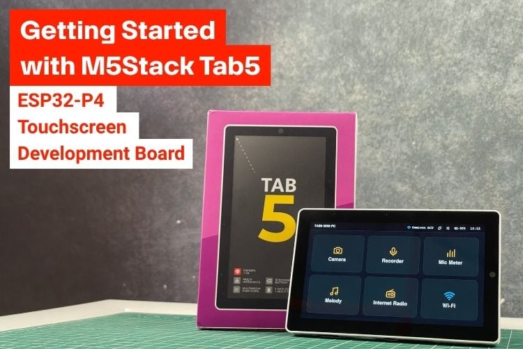
Large touchscreen development boards are useful when a project needs more than a microcontroller and a few expansion pins. A display, camera, audio system, wireless connectivity, storage and industrial interfaces can turn the development board itself into the starting point for a complete embedded product. The M5Stack Tab5 takes this approach with a 5-inch 1280 × 720 touchscreen and a dual-processor architecture built around the ESP32-P4 and ESP32-C6.
The Tab5 combines an ESP32-P4 application processor with an ESP32-C6 wireless controller, along with a 2MP MIPI camera, dual microphones, an ES8388 audio codec, a BMI270 motion sensor, an RTC, microSD storage, USB Host, USB OTG and an RS485 interface. It also provides M5-Bus and HY2.0-4P expansion, making it suitable for both user-interface projects and connected embedded systems. We will focus not only on the hardware, but also on how to get the board running and how to program it using both Arduino IDE and UIFlow 2. So let's take a closer look at the M5Stack Tab5.
What's Included with the M5Stack Tab5?
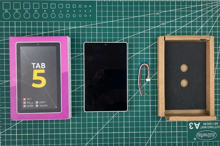
Our unit is the standard Tab5 (SKU C145). According to M5Stack, the standard package contains the Tab5 itself and a 1.25-6P single-ended terminal cable. The separate Tab5 Kit (SKU K145) adds a 2000 mAh NP-F550 battery, which is not part of the board-only package.
For our testing, we use an external NP-F550 battery with the board-only Tab5. If you are using a third-party battery, verify that it is electrically and mechanically compatible before connecting it.
Key Features of the M5Stack Tab5
The Tab5 is designed as a self-contained embedded development platform rather than simply a processor board. Its feature set covers display, touch, imaging, audio, sensing, wireless communication, storage and industrial connectivity.
| Specification |
Parameter |
| Main Controller SoC |
ESP32-P4NRW32 @ RISC-V 32-bit dual-core 360 MHz + LP single-core 40 MHz |
| Wireless Module SoC |
ESP32-C6-MINI-1U |
| Flash |
16 MB |
| PSRAM |
32 MB Octal |
| Wi-Fi |
2.4 GHz Wi-Fi 6, Thread, Zigbee |
| Antenna |
Built-in 3D antenna + 2 × MMCX external antenna ports |
| Display |
5-inch IPS TFT, 1280 × 720 (720P), integrated display/touch driver IC: ST7123 / ST7121 |
| Camera |
SC2356, 2 MP (1600 × 1200), MIPI-CSI |
| Audio Chip |
ES8388 codec + ES7210 AEC front end |
| Microphone |
Dual microphone system with AEC echo cancellation |
| Speaker |
1 W @ 8 Ω, NS4150B |
| Headphone Jack |
3.5 mm |
| USB Ports |
USB Type-A Host + USB Type-C USB 2.0 OTG |
| RS485 Port |
SIT3088, 120 Ω switchable termination resistor |
| Power Supply Range |
6–24 V |
| Expansion Interface |
1 × HY2.0-4P, 1 × M5-Bus, GPIO_EXT expansion bus |
| Storage Expansion |
microSD card slot |
| Extensible Stamp Interface |
Stamp pads; supports Cat-M, NB-IoT, LoRaWAN and other modules |
| Motion Sensor |
BMI270 six-axis accelerometer + gyroscope; interrupt wake-up |
| RTC |
RX8130CE; timed interrupt wake-up; 70,000 μF / 3.3 V RTC supercapacitor, Ø4.8 × 1.4 mm |
| Reset / Boot Button |
1 button used for power on/off and entering download mode |
| Charging Management |
IP2326 |
| Real-Time Power Monitoring |
INA226 bus current/voltage monitoring |
| Battery |
NP-F550 removable lithium battery, 7.4 V @ 2000 mAh (14.8 Wh) |
| Battery Life |
About 6 hours under the documented standard-use test condition: 50% screen brightness, Wi-Fi always on and background tasks running, from 8.23 V full to 6.0 V shutdown threshold |
| Operating Temperature |
0–40 °C |
| Product Size – Tab5 |
128.0 × 80.0 × 12.0 mm |
| Product Weight – Tab5 |
118.4 g |
| Battery Weight |
98.9 g |
| Package Size – Tab |
148.0 × 103.0 × 21.0 mm |
| Gross Weight – Tab |
161.5 g |
M5Stack Tab5 Applications and Use Cases
The combination of a large touchscreen and a broad set of interfaces makes the Tab5 useful for applications where the user interface and the embedded controller need to be developed together.
The Tab5 is suited to industrial HMI and machine-control interfaces, smart-home control panels, connected dashboards, remote monitoring terminals, IoT gateways and data-logging systems. It can also be used for portable test and measurement interfaces, camera-based monitoring and imaging, audio and voice-interface projects, RS485 and Modbus systems, robotics control panels, and educational rapid-prototyping projects.
M5Stack Tab5 Development Board: Physical Overview
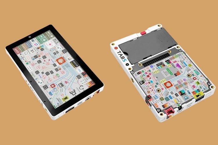
The Tab5 is built around a 5-inch touchscreen on the front and a dense expansion and interface area on the rear. The sides expose the main user-accessible connectors, while the rear carries the M5-Bus, expansion ports and battery interface.
Front of the Tab5
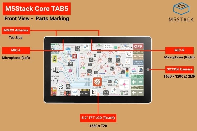
The front is dominated by the 5-inch 1280 × 720 IPS touchscreen. The 2MP SC2356 camera is positioned above the display, while the two microphones are placed near the upper left and right edges. The camera uses the ESP32-P4's MIPI-CSI interface, allowing the board to handle camera data without requiring an external USB camera.
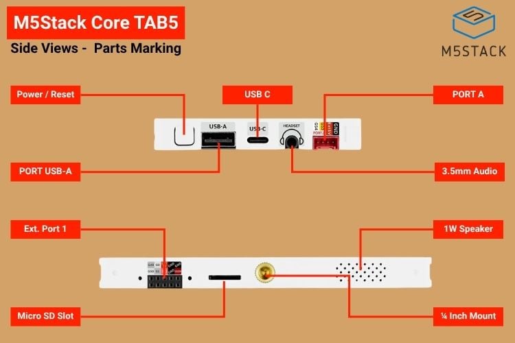
Side Interfaces
The side of the board provides the most frequently used external connections. There is a USB Type-A Host port for peripherals, a USB Type-C connector for data and OTG functions, a 3.5 mm audio connector, and an additional Port A expansion connector. The microSD slot and speaker are accessible from the opposite side, along with a standard 1/4-inch mounting point.
Rear of the Tab5
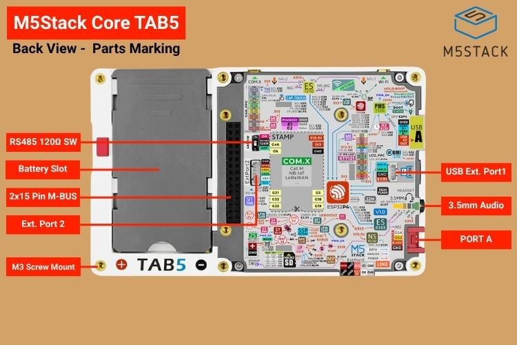
The rear side reveals the battery area and the board's expansion architecture. A 2×15-pin M5-Bus connector provides a large set of signals and power rails for M5Stack modules. The rear also exposes additional expansion pads and the RS485 termination switch.
What's Inside the M5Stack Tab5
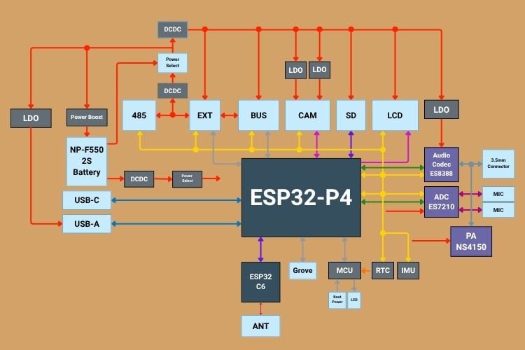
The Tab5 uses two Espressif MCUs rather than relying on a single MCU for every function. The ESP32-P4 handles the main application processing and the high-bandwidth peripherals, while the ESP32-C6 provides the wireless subsystem. This division is particularly useful for a device with a high-resolution display, camera, audio processing and network connectivity. The Tab5 is a relatively complex board, so the block diagram below is worth keeping nearby during hardware development for easy reference.
ESP32-P4 Main Controller
At the center of the Tab5 is the ESP32-P4NRW32. It is a RISC-V-based dual-core processor rated up to 360 MHz and includes an additional low-power single-core processor running at 40 MHz. The board provides 16 MB of Flash and 32 MB of Octal PSRAM, giving applications considerably more memory than a conventional small ESP32 development board.
| Parameter | Specification |
| Part Number | ESP32-P4NRW32 |
| Architecture | 32-bit RISC-V |
| CPU | Dual-core, up to 360 MHz |
| Low-Power CPU | Single-core LP processor, 40 MHz |
| Flash | 16 MB |
| PSRAM | 32 MB Octal |
| Display Interface | MIPI-DSI |
| Camera Interface | MIPI-CSI |
| USB | USB 2.0 OTG |
ESP32-C6 Wireless Controller
Wireless connectivity is handled by an ESP32-C6-MINI-1U module. The Tab5 documentation lists 2.4 GHz Wi-Fi 6 together with Thread and Zigbee support. The board includes a built-in 3D antenna and two MMCX external antenna connections, with onboard circuitry used to select between internal and external antenna paths.
| Parameter | Specification |
| Module | ESP32-C6-MINI-1U |
| CPU | 32-bit RISC-V single-core |
| Maximum Frequency | 160 MHz |
| Wi-Fi | 2.4 GHz Wi-Fi 6 |
| Bluetooth | Bluetooth 5 LE |
| IEEE 802.15.4 | Thread and Zigbee |
| Flash | Up to 8 MB in module |
| Antenna | External antenna connector |
| Interface to ESP32-P4 | SDIO |
Display and Touchscreen
The 5-inch IPS TFT display has a 1280 × 720 resolution. The display uses a high-speed DSI connection to the ESP32-P4, while the touch controller communicates over I²C. Depending on the hardware revision, the documentation identifies ST7123/ST7121 touch/display controller combinations.
| Display Parameter | Specification |
| Panel | 5-inch IPS TFT |
| Resolution | 1280 × 720 pixels |
| Touch | Capacitive touchscreen |
| Display interface | MIPI DSI |
| Touch interface | I²C |
| Touch interrupt | ESP32-P4 GPIO23 |
Camera
The Tab5 includes an SC2356 image sensor capable of 1600 × 1200 resolution. It connects to the ESP32-P4 using MIPI-CSI. The camera control signals use GPIO32 and GPIO31 for I²C, with GPIO36 used for the camera master clock; the CSI differential data and clock lanes are dedicated to the camera interface.
| Parameter | Specification |
| Sensor | SC2356 |
| Resolution | 2 MP |
| Maximum Resolution | 1600 × 1200 pixels |
| Interface | MIPI-CSI |
| Configuration Interface | I²C |
| Application | Image capture, video and edge-AI applications |
Audio Section
Audio is another major part of the Tab5 design. The ES8388 provides audio codec functions, while the ES7210 is used as the analog-to-digital front end for the dual microphones and echo-cancellation path. A 1 W, 8 Ω speaker is driven through the onboard amplifier, and a 3.5 mm connector is provided for headphones.
| Audio Block | Specification |
| Codec | ES8388, I²C address 0x10 |
| Microphone ADC / AEC | ES7210, I²C address 0x40 |
| Microphones | Two onboard microphones |
| Speaker | 1 W, 8 Ω |
| Headphone output | 3.5 mm connector |
| Audio bus | I²S |
BMI270 IMU
The onboard BMI270 provides 3-axis acceleration and 3-axis angular-rate measurement. It is connected through the shared internal I²C bus at address 0x68 and supports interrupt-based wake-up.
| Parameter | Specification |
| Sensor Type | 6-axis IMU |
| Accelerometer | 3-axis, 16-bit |
| Gyroscope | 3-axis, 16-bit |
| Accelerometer Range | ±2 g, ±4 g, ±8 g, ±16 g |
| Gyroscope Range | ±125, ±250, ±500, ±1000, ±2000 °/s |
| Accelerometer ODR | 12.5 Hz to 1.6 kHz |
| Gyroscope ODR | 25 Hz to 6.4 kHz |
| Interface | I²C |
| I²C Address | 0x68 |
| Interrupt | Motion/interrupt wake-up |
Real-Time Clock and Power Monitoring
The RX8130CE RTC chip provides the real-time clock and timed interrupt functions. The INA226 monitors bus voltage and current, allowing the firmware to obtain power-related measurements. These features are useful in portable instruments, data loggers and battery-powered monitoring systems.
| Parameter | Specification |
| Device | RX8130CE |
| Function | Real-Time Clock |
| Interface | I²C |
| I²C Address | 0x32 |
| Backup Current | 300 nA typical @ 3 V |
| Accuracy | ±23 ppm @ 25 °C |
| Operating Temperature | −40 to +85 °C |
| Interrupt | Timed interrupt/wake-up |
| Clock Source | Integrated 32.768 kHz crystal |
USB Interfaces
The USB Type-A connector operates as a Host interface, allowing the Tab5 to work with USB peripherals. The USB Type-C connector provides USB 2.0 OTG functionality and is also used during development and firmware programming.
RS485 Interface
For industrial communication, the Tab5 includes an SIT3088 RS485 transceiver. The interface uses separate receive, transmit and direction signals from the ESP32-P4. A switchable 120 Ω termination resistor is provided on the rear of the board, which is useful when the Tab5 is positioned at the end of an RS485 bus.
| Parameter | Specification |
| Device | SIT3088 |
| Interface | RS485 |
| Application | Industrial differential serial communication |
| Interface with ESP32-P4 | UART |
| Use | Half-duplex RS485 communication |
| Termination | 120 Ω switchable |
MicroSD Storage
A microSD card slot is available for local storage. The hardware supports both SPI and SDIO-style connections, with the ESP32-P4 providing the required signals.
Expansion Interfaces
The rear M5-Bus exposes a large set of power, GPIO, UART, SPI and I²C-related signals. The Tab5 also includes a HY2.0-4P Port A and additional expansion pads. These interfaces let you connect M5Stack modules and custom circuitry without modifying the main PCB.
Tab5 Board PinMap Overview
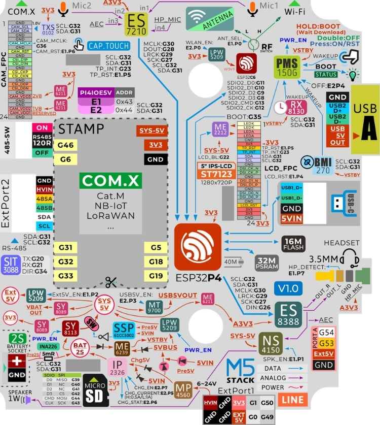
Most users will not need to work directly with the internal GPIO assignments when using M5Unified. Still, the pin map is valuable when developing custom hardware or using lower-level APIs and for better understanding of how the TAB5 hardware is actually working. Here is the Tab5 board pin map overview image, which is also available as a sticker on the read side of the Tab5 itself for easy reference.
Tab5 Pin Map and Internal Connections
Most users will not need to work directly with the internal GPIO assignments when using M5Unified, but the pin map is valuable when developing custom hardware or using lower-level APIs. The following table summarises the main internal connections documented by M5Stack. The table below shows the entire internal connections of the Tab5.
| Category | Peripheral / Device | Controller / Address | Signal | Pin / Value | Description |
| Camera | SC2356 Camera | ESP32-P4 | CAM_SCL | G32 | I²C clock line used to configure and control the SC2356 camera. |
| CAM_SDA | G31 | I²C data line used to configure and control the SC2356 camera. | |||
| CAM_MCLK | G36 | Master clock supplied to the SC2356 camera sensor. | |||
| CAM_D1P | CSI_DATAP1 (Dedicated) | Positive differential data lane 1 of the MIPI-CSI camera interface. | |||
| CAM_D1N | CSI_DATAN1 (Dedicated) | Negative differential data lane 1 of the MIPI-CSI camera interface. | |||
| CAM_CSI_CKP | CSI_CLKP (Dedicated) | Positive differential clock lane of the MIPI-CSI camera interface. | |||
| CAM_CSI_CKN | CSI_CLKN (Dedicated) | Negative differential clock lane of the MIPI-CSI camera interface. | |||
| CSI_DOP | CSI_DATAP0 (Dedicated) | Positive differential data lane 0 of the MIPI-CSI camera interface. | |||
| CSI_DON | CSI_DATAN0 (Dedicated) | Negative differential data lane 0 of the MIPI-CSI camera interface. | |||
| Audio | ES8388 | ES8388 (0x10) | MCLK | G30 | Master clock for the audio codec/microphone audio interface. |
| SCLK | G27 | Serial audio clock used by the I²S interface. | |||
| DSDIN | G26 | Serial digital audio data input to the ES8388 codec. | |||
| LRCK | G29 | Left/right clock, also used as the I²S word-select signal. | |||
| SCL | G32 | I²C serial clock line. | |||
| SDA | G31 | I²C serial data line. | |||
| ES7210 | ES7210 (0x40) | MCLK | G30 | Master clock for the audio codec/microphone audio interface. | |
| SCLK | G27 | Serial audio clock used by the I²S interface. | |||
| ASDOUT | G28 | Serial digital audio data output from the ES7210 microphone ADC. | |||
| LRCK | G29 | Left/right clock, also used as the I²S word-select signal. | |||
| SCL | G32 | I²C serial clock line. | |||
| SDA | G31 | I²C serial data line. | |||
| Display | LCD | ST7123 / ST7121 | LEDA | G22 | LCD backlight LED power/control connection. |
| DSI_CK_N | DSI_CLKN (Dedicated) | Negative differential clock lane of the MIPI-DSI display interface. | |||
| DSI_CK_P | DSI_CLKP (Dedicated) | Positive differential clock lane of the MIPI-DSI display interface. | |||
| DSI_D1_N | DSI_DATAN1 (Dedicated) | Negative differential data lane 1 of the MIPI-DSI display interface. | |||
| DSI_D1_P | DSI_DATAP1 (Dedicated) | Positive differential data lane 1 of the MIPI-DSI display interface. | |||
| DSI_D0_N | DSI_DATAN0 (Dedicated) | Negative differential data lane 0 of the MIPI-DSI display interface. | |||
| DSI_D0_P | DSI_DATAP0 (Dedicated) | Positive differential data lane 0 of the MIPI-DSI display interface. | |||
| Touch | ST7123 (0x55) | SDA | G31 | I²C serial data line. | |
| SCL | G32 | I²C serial clock line. | |||
| TP_INT | G23 | Touch-controller interrupt signal used to indicate touch activity. | |||
| Sensors & Monitoring | BMI270 | BMI270 (0x68) | SCL | G32 | I²C serial clock line. |
| SDA | G31 | I²C serial data line. | |||
| RX8130CE | RX8130CE (0x32) | SCL | G32 | I²C serial clock line. | |
| SDA | G31 | I²C serial data line. | |||
| INA226 | INA226 (0x41) | SCL | G32 | I²C serial clock line. | |
| SDA | G31 | I²C serial data line. | |||
| Interrupt Wakeup | PMS150G-U06 | INT(E_TRG) | PA6/CIN- | Interrupt source used for wake-up; connected to BMI270 / RTC interrupt path. | |
| BMI270 (0x68) | INT(E_TRG) | PMS150G-U06 | BMI270 interrupt routed to the wake-up controller. | ||
| RX8130CE | INT(E_TRG) | PMS150G-U06 | RTC interrupt routed to the wake-up controller. | ||
| Wireless | ESP32-C6 | ESP32-C6 | SDIO2_D0 | G11 | ESP32-C6 SDIO data bit 0. |
| SDIO2_D1 | G10 | ESP32-C6 SDIO data bit 1. | |||
| SDIO2_D2 | G9 | ESP32-C6 SDIO data bit 2. | |||
| SDIO2_D3 | G8 | ESP32-C6 SDIO data bit 3. | |||
| SDIO2_CMD | G13 | ESP32-C6 SDIO command line. | |||
| SDIO2_CK | G12 | ESP32-C6 SDIO clock line. | |||
| RESET | G15 | Reset control signal for the ESP32-C6 wireless controller. | |||
| IO2 | G14 | ESP32-C6 GPIO2 control connection. | |||
| Storage | microSD | ESP32-P4 | MISO | G39 | SPI mode |
| CS | G42 | SPI mode | |||
| SCK | G43 | SPI mode | |||
| MOSI | G44 | SPI mode | |||
| DAT0 | G39 | SPI mode | |||
| DAT1 | G40 | SPI mode | |||
| DAT2 | G41 | SPI mode | |||
| DAT3 | G42 | SPI mode | |||
| CLK | G43 | SPI mode | |||
| CMD |
G44 |
SPI mode | |||
| Industrial | RS485 | SIT3088 | RX | G21 | RS485 receive-data connection from the SIT3088 transceiver. |
| TX | G20 | RS485 transmit-data connection to the SIT3088 transceiver. | |||
| DIR | G34 | RS485 transmit/receive direction control for the SIT3088 transceiver. | |||
| Expansion | HY2.0-4P / PORT.A | ESP32-P4 | GND | Black | Ground reference for the interface. |
| 5V | Red | 5 V supply output for the connected expansion device. | |||
| G53 | Yellow | ESP32-P4 GPIO53 signal on Port A. | |||
| G54 | White | ESP32-P4 GPIO54 signal on Port A. | |||
| I/O Expander | PI4IOE5V6408-1 | 0x43 | SCL | G32 | I²C clock |
| SDA | G31 | I²C data | |||
| RST | CHIP_PU | Reset | |||
| PI4IOE5V6408-2 | 0x44 | SCL | G32 | I²C clock | |
| SDA | G31 | I²C data | |||
| RST | CHIP_PU | Reset | |||
| PI4IOE5V6408-1 | 0x43 | E1.P0 | RF_PTH_L_INT_H_EXT | Low = internal Wi‑Fi antenna; High = external antenna. | |
| E1.P1 | RF_INT_EXT_SWITCH | Antenna-path control switch. | |||
| E1.P1 | SPK_EN | NS4150B speaker amplifier enabled. | |||
| E1.P2 | EXT5V_EN | NS4150B speaker amplifier enabled. | |||
| E1.P2 | EXT_5V_BUS | Provides 5 V to the rear M5-Bus, side 2.54-10P expansion port and HY2.0-4P interface. | |||
| E1.P4 | LCD_RST | LCD reset control. | |||
| E1.P5 | TP_RST | Touch-panel reset control. | |||
| E1.P6 | CAM_RST | Camera reset control. | |||
| E1.P7 | HP_DET | Headphone detection. | |||
| PI4IOE5V6408-2 | 0x44 | E2.P0 | WLAN_PWR_EN | Enables power to the internal ESP32-C6 wireless SoC. | |
| E2.P3 | USB5V_EN | USB-A 5 V power enable. | |||
| E2.P4 | PWROFF_PLUSE | Device power-off control pulse. | |||
| E2.P5 | nCHG_QC_EN | Charging / QC control. | |||
| E2.P6 | CHG_STAT_LED | Charging-status LED control. | |||
| E2.P7 | CHG_EN | Charging enable control. |
M5-Bus Expansion Connector Overview
The Tab5 also integrates an M5-Bus connector, which can be used to expand Module series products. The following table shows the M5-Bus pinout.
| Function | PIN | M5-Bus | PIN | Function | |
| GND | GND | 1 | 2 | G16 | GPIO |
| GND | 3 | 4 | G17 | PB_IN | |
| GND | 5 | 6 | RST | EN | |
| MOSI | G18 | 7 | 8 | G45 | GPIO |
| MISO | G19 | 9 | 10 | G52 | PB_OUT |
| SCK | G5 | 11 | 12 | 3V3 | 3V3 |
| RXD0 | G38 | 13 | 14 | G37 | TXD0 |
| PC_RX | G7 | 15 | 16 | G6 | PC_TX |
| Int SDA | G31 | 17 | 18 | G32 | Int SCL |
| GPIO | G3 | 19 | 20 | G4 | GPIO |
| GPIO | G2 | 21 | 22 | G48 | GPIO |
| GPIO | G47 | 23 | 24 | G35 | GPIO |
| HVIN | HVIN | 25 | 26 | G51 | GPIO |
| HVIN | 27 | 28 | 5V | 5V | |
| HVIN | 29 | 30 | BAT | BAT | |
Powering the M5Stack Tab5
When the device is powered by a USB data cable or battery, press the power button once to power it on while it is off. While it is on, double-press the power button to shut it down.
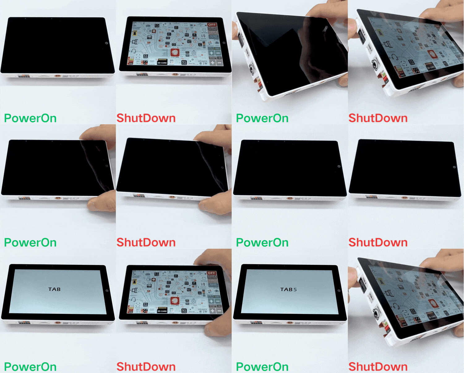
M5Stack recommends shutting the device down before disconnecting power or replacing the battery. If power is disconnected directly, the documentation recommends waiting about five seconds before powering the board again because the IMU may otherwise fail to initialise correctly. For charging, the battery can only be charged after the Tab5 has powered on and completed initialization. If the battery has entered protection because its voltage has fallen below 6 V, the manufacturer's recovery procedure should be followed before charging.
Installing the NP-F550 Battery
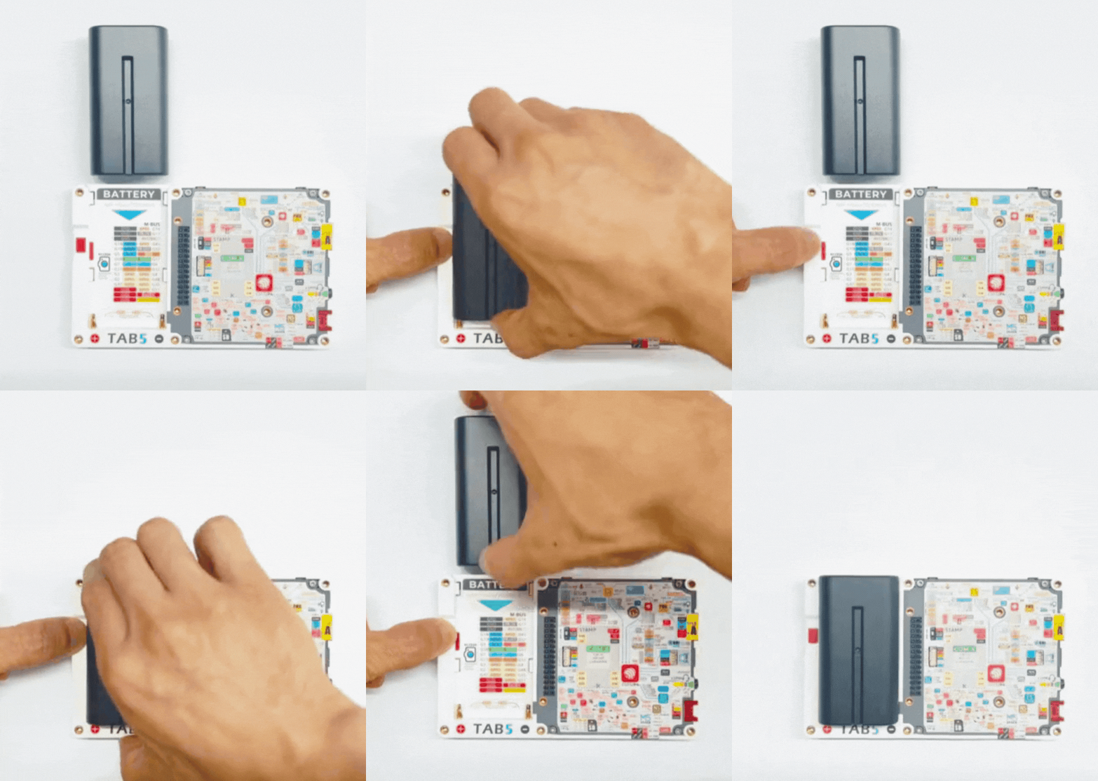
With the Tab5 powered off, press and hold the red battery locking button, align the battery's metal contacts with the BATTERY slot, slide the battery down along the guide rail until it is seated flush with the board, and release the locking button to secure it.
Resetting and Entering Download Mode
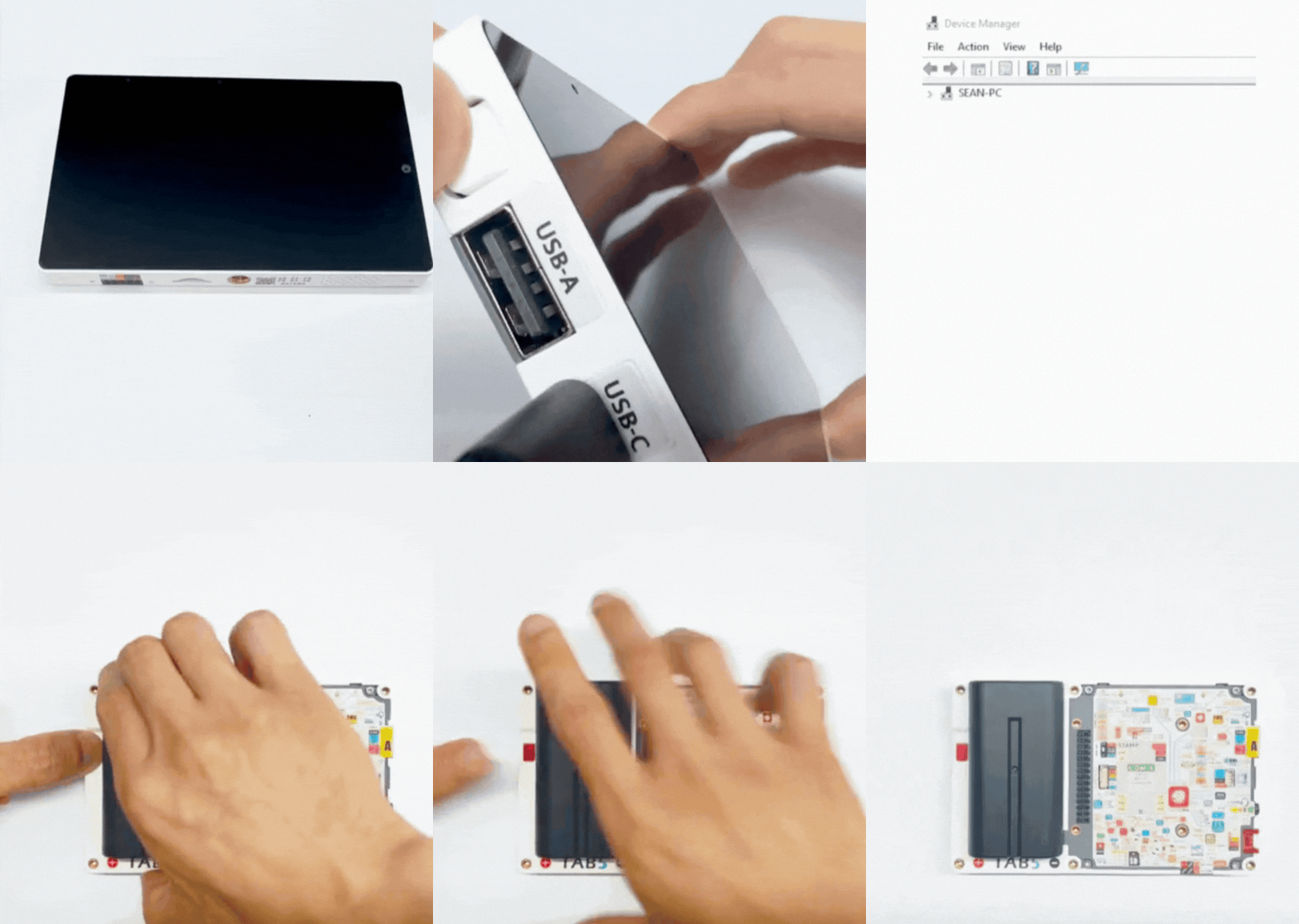
The same physical button also provides access to the firmware download mode. With the Tab5 connected to USB or powered by its battery, press and hold the Reset/Power button for about two seconds. Watch the internal green LED: when it starts flashing rapidly, release the button. The Tab5 is then in download mode and waiting for firmware to be written. This procedure is used by Arduino, M5Burner and the UIFlow 2 firmware flashing workflow.
Factory Firmware and Built-In Hardware Demonstration
The Tab5 ships with a factory user-demo firmware intended to demonstrate the board's hardware. This factory demo is useful as a first diagnostic tool because it lets you check the major peripherals before writing any Arduino or UIFlow 2 code. The factory interface includes functional panels for the RTC, display backlight, speaker volume, power monitoring, IMU, power and switch control, camera, dual-microphone recording, headphone microphone testing, SD card access, I²C scanning, GPIO testing, music playback and serial/COM monitoring.
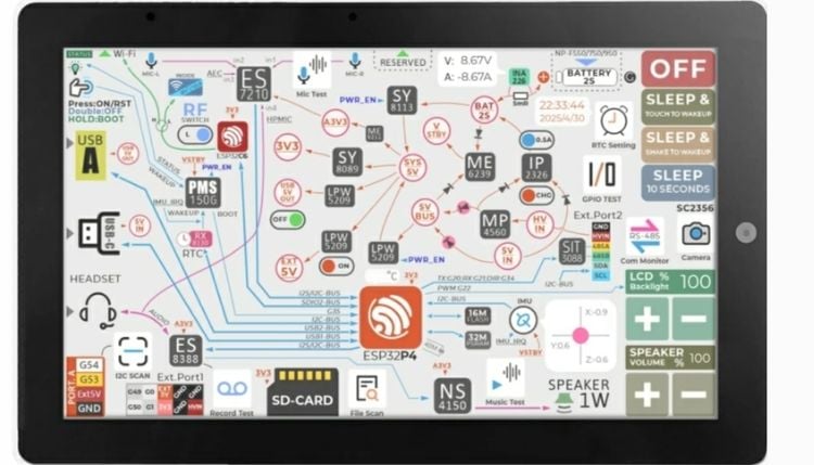
The RTC panel displays the real-time clock and provides RTC-related controls. The LCD backlight panel allows the display brightness to be adjusted. The speaker panel controls output volume, while the power-monitoring panel exposes voltage, current and related system information from the INA226. The IMU panel provides acceleration and gyroscope readings from the BMI270. The SD-card test scans the card and displays its available content. The I²C scan function can be used to identify responding devices on the internal I²C bus, and the GPIO test allows supported GPIOs to be exercised. The COM monitor provides a simple way to check serial communication.
ESP32-C6 Wireless Firmware
The ESP32-C6 inside the Tab5 is normally preloaded with M5Stack's Wi-Fi SDIO firmware. If the wireless module has been overwritten or its Wi-Fi function stops working, M5Stack provides a separate C6 firmware restoration procedure. The PCB includes a reserved download interface for the ESP32-C6, and M5Stack documents using a USB-TTL adapter or its ESP32 Downloader to access that interface. This is a separate operation from flashing the main ESP32-P4 application firmware.
Programming the M5Stack Tab5 with Arduino IDE
Using the Tab5 with the Arduino IDE is very easy, as with any other Arduino IDE-supported development board. Arduino setup begins by installing the Arduino IDE and the M5Stack board package, selecting M5Tab5 from the board list, and installing M5Unified and M5GFX through Library Manager. To install the M5Stack board manager, copy and paste the following M5Stack board manager URL below into the Additional Board Manager URLs field in the Arduino IDE preferences menu, and save.
https://static-cdn.m5stack.com/resource/arduino/package_m5stack_index.j…;
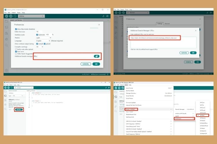
Later in the Board Manager, search for M5Stack and click Install. Once the Board Manager package is fully installed, select the M5Tab5 board from the board list. You should also install the M5Unified and M5GFX driver libraries via the library manager.
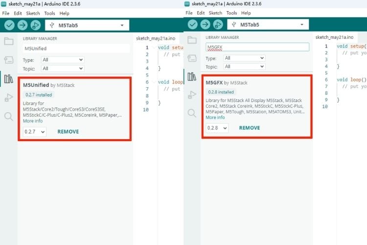
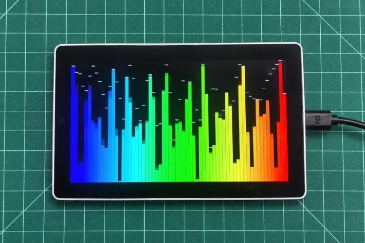
With USB connected or the board powered from its battery, press and hold the reset button for about two seconds. When the internal green LED begins flashing rapidly, release the button. The board is then waiting for firmware download. After the USB connection is established, open Tools > Port and select the serial port associated with the Tab5. The exact port name depends on the operating system and USB configuration. If no new port appears, try another USB cable first because many USB cables provide power only. The M5Unified and M5GFX libraries come with a number of examples for us to use. For now, we will use the BarGraph example. Open the sample program "BarGraph" in the M5GFX driver library, then click the upload button to automatically compile and flash the program. The example runs as follows:
Tab5 Power Management and External Outputs in Arduino
The M5Unified library also exposes the Tab5 power-management functions. The board's 5 V outputs for the M5-Bus, HY2.0-4P, 2.54-10P expansion bus and USB-A are enabled by default when M5.begin() is called. They can be controlled in software when an application needs to reduce external power consumption or disconnect a peripheral.
For example, an Arduino application can disable the shared expansion power with M5.Power.setExtOutput(false, m5::ext_port_mask_t::ext_PA) or disable USB-A power with M5.Power.setExtOutput(false, m5::ext_port_mask_t::ext_USB). Calling M5.Power.setExtOutput(true) restores the external outputs. The same Power class can report charging status, battery voltage and battery level, making it useful for battery-powered interfaces.
M5.Power.setExtOutput(false, m5::ext_port_mask_t::ext_PA);
M5.Power.setExtOutput(false, m5::ext_port_mask_t::ext_USB);
bool charging = M5.Power.isCharging();
int voltage = M5.Power.getBatteryVoltage();
int level = M5.Power.getBatteryLevel();
Programming the M5Stack Tab5 with UiFlow 2
UIFlow 2 provides a block-based programming workflow for the Tab5. Instead of writing a complete C++ application, you can build the program by connecting Blockly blocks and then run or download the generated program to the board. It is particularly useful for quickly testing the display, touch, sensors and network functions before moving to a conventional code-based environment. To familiarise yourself with the UiFlow2 web IDE, refer to the official UiFlow2 Web IDE Tutorial.
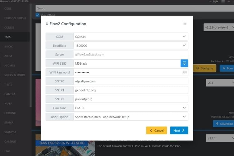
The first step to program the Tab5 with UiFlow2 is to flash the UIFlow 2 firmware into the Tab5. You can do that either via the M5Burner offline tool or the M5Burner web version. To do so, first put the Tab5 into download mode using the power button while connected to the computer. Open the M5Burner tool and use the burn button for the UIFlow 2 firmware, then select the correct COM port and click Start. Then fill in the Wi-Fi credentials, as well as any other device configurations that need to be added or modified, and click Next to start flashing.
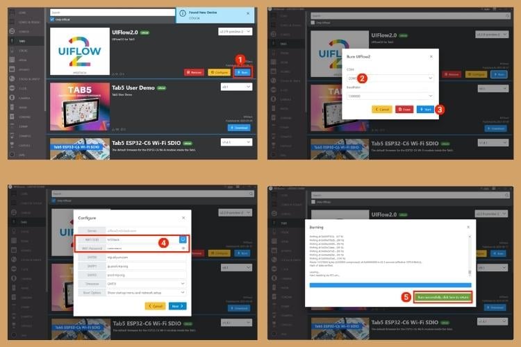
After firmware flashing is complete, if you need to modify the device configuration, keep the USB connection, restart the device, click the Configure option, and modify the configuration according to the on-screen prompts.
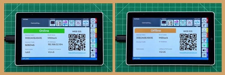
Now, once everything is configured, you can connect the Tab5 with UniFlow2 via wireless network or USB, which enables program upload and debugging. To use the wireless connection, make sure the Tab5 is connected to the WiFi. If it's not connected, check and verify the WiFi configuration and modify it if necessary using the configuration option in the M5Burner. Make note of the access code on the screen, which will be used to connect to the UiFlow2.
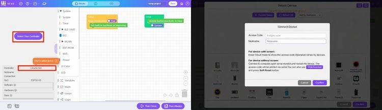
To open the UiFlow2 Web IDE, visit uiflow2.m5stack.com. Click Select Your Controller (displayed on first entry) or the Controller button on the page to enter the Select Device page. Click Connect Device, enter the access code and a custom device name, then click Confirm to connect Tab5 to UiFlow2. Select the connected Tab5 device on the Select Device page, then click Confirm to enter the UiFlow2 programming interface. Keep in mind that changing browsers, using private/incognito mode, or clearing the UiFlow website cache will invalidate the original pairing state. In such cases, you must pair it again with the IDE.
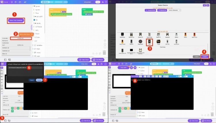
To connect the Tab5 using USB, make sure the board is plugged into the PC, then click Select Your Controller (displayed on first entry) or the Controller button on the page to enter the Select Device page. On the Select Device page, select the Tab5 device in the device list and click Confirm. Then click the WebTerminal button, select the serial port of Tab5 in the dialog box, and click Connect. When the WebTerminal screen displays Connected to Serial Port!, the USB connection is successful.
Once the device is connected to UiFlow2, you can drag Blockly blocks to edit programs.
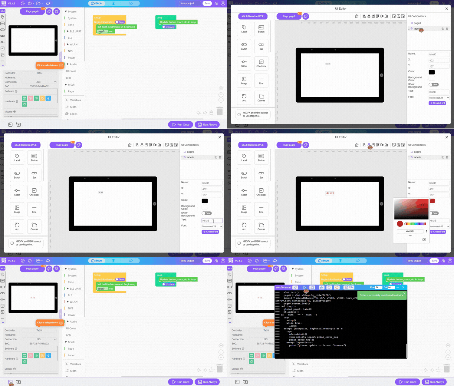
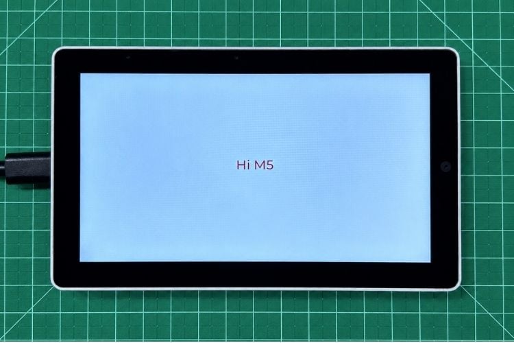
After editing the program, click the Run Once button in the lower-right corner of the interface to run the test program once. Click the Run Always button to download the program to the device.
Troubleshooting
Tab5 does not appear as a USB port
If the Tab5 does not appear as a USB device, first try a known-good USB data cable rather than a charge-only cable, then try another USB port, confirm that the board is in download mode and check the operating system for a newly detected serial device.
Arduino upload does not start
If Arduino upload does not start, confirm that M5Tab5 is selected, verify the serial port, enter download mode manually if necessary, and update M5Unified and M5GFX if the error appears to be related to display initialisation or driver compatibility.
Display does not initialise correctly
If the display does not initialise correctly, update M5Unified and M5GFX, use the Tab5-specific examples supplied by M5Stack as a known-good reference, and avoid mixing older driver libraries with newer Tab5 hardware revisions.
UIFlow 2 cannot connect wirelessly
If UIFlow 2 cannot connect wirelessly, verify the Wi-Fi credentials entered during firmware flashing, check the Access Code shown on the startup screen, and avoid changing browsers, using private browsing or clearing the UIFlow website data after pairing. If required, reconnect through USB and use WebTerminal.
The IMU does not initialise after power removal
If the IMU does not initialise after power removal, shut the Tab5 down before disconnecting the battery or external supply. If power was removed directly, wait about five seconds before powering the board again, then retest the IMU with the official M5Stack example.
Sample Code GitHub Repository
We have created an Arduino example for the M5Stack Tab5 to help users get started with programming and testing the board.



Add a comment
No account needed. Your comment appears once a moderator has reviewed it.